Table of Contents
Advertisement
Advertisement
Table of Contents

Related Manuals for Nexxt webwise


Summary of Contents for Nexxt webwise
- Page 1 WebWise 16/24 Port Gigabit Ethernet Switch User`s Manual...
- Page 2 Upgrades of software and hardware may occur, and should there be any changes, Nexxt Solutions shall not be responsible for notifying about any such modifications in advance. If you would like to know more about our products, please visit...
-
Page 3: Table Of Contents
CONTENTS Chapter 1 Product Overview 1.1 Features 1.2 Package Contents Chapter 2 Hardware Installation 2.1 Front Panel 2.2 Rear Panel 2.3 Environmental Requirements 2.4 Hardware Installation Chapter 3 Configuration 3.1 Fast Login 3.2 Status 3.3 Port Setting 3.3.1 Port 3.3.2 Rate Limit 3.3.3 Storm Control 3.3.4 Statistics 3.4 Mirror... - Page 4 CONTENTS 3.10.1 RSTP 3.10.2 RSTP Port 3.10.3 RSTP Status 3.11 IGMP Snooping 3.11.1 Snooping Configuration 3.11.2 Snooping Status 3.12 System 3.12.1 SNMP 3.12.2 Change Password 3.12.3 Cable Diagnostics 3.12.4 Upgrades 3.12.5 IP Configuration 3.12.6 MAC Aging 3.12.7 Restoring Factory Configuration 3.12.8 Backup 3.12.9 Restore 3.12.10 Logout...
-
Page 5: Chapter 1 Product Overview
Chapter 1-- Product Overview Thank you for purchasing this high performance 16/24 port Web Wise Switch. The NW223NXT56/NW223NXT57 is a rack-mountable Gigabit Ethernet Switch, specially designed for small to medium businesses that require high performance network connectivity along with advanced web management capabilities. It features UTP/STP RJ-45 ports with auto MDI/MDIX, which can operate at 10/100/1000Mbps. - Page 6 • Supports IEEE802.3x flow control for full duplex, and backpressure flow control for half duplex. • Store and forward architecture, integrated 8K MAC address table, and meets all application demands. • Up to 32/48Gbps backplane bandwidth, and supports non- blocking line speed forwarding. •...
-
Page 7: Package Contents
port. • Equipped with a universal power supply, and a 1U steel chassis for standard installation in a 19-inch rack. 1.2 Package Contents Upon opening the box, ensure that the following items are included: • Gigabit Ethernet Switch NW223NXT56/NW223NXT57 • One power cord •... -
Page 8: Front Panel
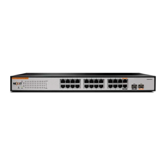
Chapter 2 Hardware Installation 2.1 Front Panel The NW223NXT56/NW223NXT57 switches include the following main components: network ports, status indicators and a reset button, as shown below. Front Panel of the 24-port switch Front Panel of the 16-port switch Status indicators: Every Giga port provides 1 Link/Act Port, 1 100Mbps indicator, and 1 1000Mbps indicator. - Page 9 LED Indicator Color Status Description It is “on” when the Switch is Orange Light turned on. If this indicator is off, check the POWER AC power connector to ensure proper insertion of the power cord and if the power switch is turned on.
-
Page 10: Network Ports
settings, and restore the switch to its factory default configuration. How to use the RESET button: To restore the default settings, press and hold the “Reset” button when the switch is on; the indicator will change from light/blinking/off, then release the “Reset” button. -
Page 11: Rear Panel
To extend your network to over 100 meters, you need to have an optical connection available. Please log on to our website www.Nexxt Solutions.cn, to get more information about optical fiber, the SFP optical module, and optical network construction. 2.2 Rear Panel The rear panel provides an AC input socket, as shown below. -
Page 12: Hardware Installation
sure to leave a space of at least 10cm on each side around the switch, for better heat dissipation. • Environmental humidity: 5%-95%, without condensation. Do not place the switch in an extremely dirty or damp place. • Keep the switch away from strong electric/magnetic fields. - Page 13 NW223NXT56/NW223NXT57 L-shape supports (the 24-port model is used as an example) Installation of the NW223NXT56/NW223NXT57 Network connection: The NW223NXT56/NW223NXT57 supports 10/100/1000 Mbps Ethernet, 10/100 Mbps half/full- duplex mode and 1000 Mbps full-duplex mode. All RJ-45 ports support Auto MDI/MDIX function. They can be used as ordinary ports or Uplink backbone cascading ports.
- Page 14 Network transmission media: RJ45 ports support CAT5/CAT5 or higher category of STP/UTP cabling. CAT6 UTP cable is recommended to ensure stable data transmission at 1000 Mbps. LC fiber connectors are used for the SFP modules. Caution! Make sure that only one uplink connection exists between switches (except for the Trunk function) or between the switch and HUB, otherwise the multi-uplink connection could form a loop that makes the entire...
-
Page 15: Chapter 3 Configuration
Chapter 3 Configuration 3.1 Fast Login Since the NW223NXT56/NW223NXT57 is not equipped with an internal DHCP server, you need to manually configure the IP address of the computer for login and configuration. The table below lists the default parameters of the switch. Parameter Default Value Default IP address... -
Page 16: Status
On the left column of the menu bar, you will find “Status”, “Port Setting”, “Mirror”, “VLAN”, “Trunk”, “QoS”, “MAC Address Setting”, “802.1X Setting”, “RSTP Setting”, “IGMP Snooping” and “System”. Click any menu item to set the corresponding function. The setting procedure will be described in detail later in this manual. -
Page 17: Port Setting
3.2 System Status The following window displays basic system information. • Hardware Version: Hardware version of the switch. • Firmware Version: Software version of the switch. • DHCP Client: Status of the DHCP client, “Disable” by default. • IP Address: “192.168.0.1” (default). •... -
Page 18: Port
with the corresponding device. Flow control is used to set the data flow and prevents the buffer overflow of the receiving device. The port management setting will affect port bandwidth control, port mirroring and trunking functions. 3.3.1 Port Port configuration: Only the ports belonging to the same VLAN group can communicate together;... -
Page 19: Rate Limit
necessary). • Auto Negotiate: Enable or disable the auto negotiation function of the port. (Caution: You must “Disable” the Auto negotiation function before selecting the “Duplex/Speed” setting). • Duplex/Speed: Allows the selection of the 10 Mbps full-duplex and half-duplex mode, 100 Mbps full-duplex and half-duplex mode or 1000 Mbps full-duplex mode for the port. - Page 20 is applicable to the Internet bar and community broad- band access applications. • Port: Allows the selection of the corresponding port number 16/24 and the setting network speeds of 10/100/1000 Mbps, either in half or full duplex modes. • Policer: Controls the receiving rate by level. Available rates are: 128 Kbps;...
-
Page 21: Storm Control
3.3.3 Storm Control Storm Control: Also known as traffic suppression, this feature selectively blocks the transfer of broadcast packets from the switch. When different types of broadcast packets reach the set threshold of a port, the switch automatically discards excessive packets, to prevent being disrupted by a broadcast, multicast, or unicast traffic storm on physical interfaces. -
Page 22: Statistics
3.3.4 Statistics Statistics: Displays the currently received and transmitted data, including the number of error frames at each port. • Clear button: Use this button to erase all the counter values. • Renew button: Use this button to refresh statistical data. -
Page 23: Mirror
3.4 Mirror • Mirror function is used to duplicate the traffic from one or more mirrored ports to a mirror port; this function is used to monitor the internet access. • If the mirror and mirrored ports are the same, the system will automatically ignore this mirrored port. -
Page 24: Vlan Mode
multicast, broadcast and unknown unicast packets, are to be transferred only within the VLAN. In addition, VLAN can be used to change the topological structure of the network, without any movement of network workstations or change of network connections. You can modify the VLAN setting of a workstation, to “move”... -
Page 25: Port Vlan
3.5.2 VLAN Port Description of VLAN Port configuration: A port based VLAN uses the physical ports of the switch to distinguish VLANs. • VLAN Group: Includes all 16/24 ports. Default VLAN has a VLAN ID of 1. • VLAN Member: Adds the physical ports of the switch to be included in this VLAN. -
Page 26: 802.1Q Vlan
3.5.3 802.1Q VLAN Description of 802.1Q VLAN configuration: In the VLAN Tag mode, port VID is used to identify a particular VLAN. When data frames pass through the switch, the VID tag uses the frame header to define the different VLANs, so the switch can determine the destination ports of such frames according to the current VLAN settings. -
Page 27: Tag Vlan Configuration
3.5.4 Tag VLAN Configuration Description of 802.1Q VLAN port configuration: • Port Tag: Sets the Tag attributes for the port. The port Tag rule specifies the changes to be made upon the frame output, that is, the egress rule. The available rules are “add”... -
Page 28: Trunk
3.6 Trunk • Trunk is used to expand the bandwidth (e.g. hot backup and error tolerance of the inter-switch cascading the Uplink channels). • All ports set as the trunk group members can be used by the trunk group only and cannot be used for any other purpose, even when they are not being used by the trunk group. -
Page 29: Qos
3.7 QoS • Simple QoS functions can be implemented through the combination of priority mode settings and priority control operations. This switch supports packet mapping by 4 priority levels (low, medium, common, and high) and 3 priority setting modes. - Page 30 • If “Port Priority” is enabled and a high priority is assigned to a physical port, all packets passing through this port are mapped into high priority. As a result, the switch processes the received/transmitted packets through this port first. If “802.1Q tag Priority”...
-
Page 31: Mac Address Setting
3.8 MAC Address Setting 3.8.1 MAC Filter MAC Filter: The MAC address filter is the “black list” of the switch. These MAC addresses are cut out from the network communication when they are connected to any port on the switch. MAC Address: Enter the MAC address to be filtered. -
Page 32: Static Mac
3.8.2 Static MAC Static MAC Address: Adding a MAC address to the appointed port, the bundled MAC address will transfer data only through this port. • MAC Address: Insert the MAC address. • Port ID: Choose the port to be bundled. Static MAC Address Table: List the bound MAC addres- ses, as shown below. -
Page 33: 802.1X
3.9.1 802.1X 802.1X Configuration: • 802.1X Enabled: Enables or disables the 802.1X authentication feature. • RADIUS IP: Sets the IP address of the RADIUS server. • RADIUS UDP Port: Sets the RADIUS UDP port of the switch; the default value is 1812. •... -
Page 34: 802.1X Port
3.9.2 802.1X Port 802.1X Port Configuration • Admin State: Choose between: • Force Authorized: allows transmission of any message. • “Force Unauthorized”: allows transmission of authentication messages. • “Auto”: allows the transmission of certain messages according to the authentication result. •... -
Page 35: Rstp
the bridge level. In view of the high complexity of the RSTP algorithm, it is recommended to accept the default values. RST automatically assigns root bridge or root port, to prevent a loop condition. However, if modification to RST parameters is necessary, you should carefully read the related RSTP contents to understand them in advance. -
Page 36: Rstp Port
switch is not set as a root bridge. If a switch becomes a root bridge, this value will take effect. • Max Age: Sets a value between 6 sec and 40 sec. Indicate that the time limit of the last BPDU received is valid. -
Page 37: Rstp Status
RSTP Port Configuration: • Protocol Enabled: Enables or disables the RSTP feature. By default, this function is disabled for every port. • Edge: The edge port feature has faster status transition, and it is 2 times faster than the forwarding delay when it directly changes from blocking to forwarding status. -
Page 38: Igmp Snooping
• RSTP Bridge Overview: Displays the bridge ID, topology and root bridge ID specified by the system, including Hello time, maximum aging time and forwarding delay setting. • RSTP Port Status: Displays the P2P port, protocol and port state specified by the system, including path cost and edge port settings. -
Page 39: Snooping Configuration
3.11.1 Snooping Configuration IGMP Configuration • IGMP: Enables or disables the L2 multicast snooping function of the switch. By default, this option is not checked. • Router Ports: Selects the IGMP routing ports for multicast snooping. IGMP Configuration List: • IGMP Snooping Enabled: Enables or disables the L2 multicast snooping function of the switch of the corres- ponding VLAN. -
Page 40: Snooping Status
3.11.2 Snooping Status IGMP Status: Displays the multicast snooping function options of the corresponding VLAN. When the multicast table is not established, the “Querier” displays as “Idle”. When the switch snoops into a multicast message, the “Querier” displays as “Active”, and the value in “Queries transmitted”... -
Page 41: System
3.12 System 3.12.1 SNMP All management information and counters are stored in the Management Information Base (MIB) of the switch. Usually, the switch adopts the standard MIB-II module, able to be read by any SNMP-based NMS software. MIB data may be of either read-only or read-write mode. You can change the default SNMP community names of the switch and set access right for such community names. -
Page 42: Change Password
• SNMP Read Community: Sets the read-only community name of the SNMP information of the switch. To read the SNMP information of the switch, the SNMP management software must contain the consistent read-only communi- ty name. • SNMP Write Community: Sets the writeable community name of the SNMP information of the switch. -
Page 43: Cable Diagnostics
3.12.3 Cable Diagnostic Cable diagnostic window: Displays the status and length of the cable selected. Caution: Since cable noise may vary, the length should be used only as reference, not as an accurate value for calculating the interference level. 3.12.4 Upgrade... - Page 44 Please visit our website to obtain an upgrade package and detailed upgrade guide. Be cautious during the upgrade. It is recommended to interrupt all network connections except the network connection of the computer used for the upgrade. Do not power off the system during the upgrade, to avoid computer failure or other problems.
-
Page 45: Ip Configuration
3.12.5 IP Configuration IP Address: Sets the switch IP address, subnet mask and default gateway. • DHCP Client: Enables or disables the DHCP client. • IP Address: Changes the switch login IP address (default is 192.168.0.1). • Subnet mask: Changes the subnet mask of the switch (default is 255.255.255.0). -
Page 46: Mac Aging
3.12.6 MAC Aging The default MAC address aging time is 300s. The set value should be within 10s ~ 65535s to avoid system errors. If the “ARL Aging” field is not checked, the MAC address will not be aged. ARL Aging Configuration: ARL Aging: Check this option to enable aging. -
Page 47: Restoring Factory Configuration
3.12.7 Restore Factory Configuration Restore Factory Configuration: Click “Apply” to start restoring the switch to its factory default configuration. Caution: Log into the switch again after the restora- tion procedure is finished. If you change the default IP address before restoring the system, use the default IP address to re-login (IP address:192.168.0.1, default username: admin, default password: admin). -
Page 48: Restore
Backup Config: Backs up the current switch configura- tion. Click “Download” and select the path. 3.12.9 Restore Restore configuration from file: Restores the backup switch configuration. Click “Browse” and select the backup file, then click “Restore”. :This procedure takes about 30 seconds; do not power off or disconnect the switch or PC in the middle of the process. -
Page 49: Appendix 1 Common Commands
Appendix 1 Common Commands Common Description Commands logs into the Windows command mode (available for Windows2000 or higher version of this Operation System) ipconfig Displays the IP address, such as ipconfig /all One of the most useful commands in the TCP/IP protocol: it sends a packet to destination Host and requires the target host to reply when the packet is ping... - Page 50 Appendix 2 TCP/IP Example of Address Setting with Windows XP Open the “Control Panel” Figure 1 Click on “Network Connection” to display the “Network Connections” window (see Figure 2). Figure 2...
- Page 51 Choose “Local Area Connection”, click the right button of the mouse to choose “Properties” and activate the “Local Area Connection Properties” window. Next, choose the “Internet Protocol (TCP/IP)” item in the “This connection uses the following items” menu, and click on “Properties”. Figure 3 Choose “Use the following IP address”, fill in the IP address as: 192.168.0.xxx.
-
Page 52: Appendix 3 Online Technical Support
Appendix 3 Online Technical Support Should you have any problem during installation, please visit http://www.nexxtsolutions.com/dpg/ntContact.aspx. You may also write to us directly at: info@nexxtsolutions.com, for general questions or support or at techsupport@nexxtsolutions.com, for technical support issues and installation help. - Page 53 FCC Statement This equipment has been tested and found to comply with the limits for a Class B digital device, pursuant to part 15 of the FCC Rules. These limits are designed to provide reasonable protection against harmful interference in a residential installation.
Need help?
Do you have a question about the webwise and is the answer not in the manual?
Questions and answers