National Instruments NI Vision CVS-1450 Series User Manual
Compact vision system
Hide thumbs
Also See for NI Vision CVS-1450 Series:
- Quick start manual ,
- Getting started (18 pages) ,
- User manual (69 pages)

Related Manuals for National Instruments NI Vision CVS-1450 Series


Summary of Contents for National Instruments NI Vision CVS-1450 Series
- Page 1 NI Vision NI CVS-1450 Series User Manual NI CVS-1450 Series User Manual July 2005 373610E-01...
- Page 2 For further support information, refer to the Technical Support and Professional Services appendix. To comment on National Instruments documentation, refer to the National Instruments Web site at ni.com/info and enter the info code feedback. © 2003–2005 National Instruments Corporation. All rights reserved.
-
Page 3: Important Information
The reader should consult National Instruments if errors are suspected. In no event shall National Instruments be liable for any damages arising out of or related to this document or the information contained in it. - Page 4 These classes are known as Class A (for use in industrial-commercial locations only) or Class B (for use in residential or commercial locations). All National Instruments (NI) products are FCC Class A products. Depending on where it is operated, this Class A product could be subject to restrictions in the FCC rules. (In Canada, the Department of Communications (DOC), of Industry Canada, regulates wireless interference in much the same way.) Digital...
- Page 5 Conventions The following conventions are used in this manual: » The » symbol leads you through nested menu items and dialog box options to a final action. The sequence File»Page Setup»Options directs you to pull down the File menu, select the Page Setup item, and select Options from the last dialog box.
-
Page 6: Table Of Contents
Contents Chapter 1 NI CVS-1450 Series Overview About the NI CVS-1450 Series ...1-1 Hardware Overview ...1-1 Available Camera Bandwidth ...1-3 Software Overview ...1-4 NI-IMAQ for IEEE 1394 Cameras Driver Software...1-4 National Instruments Application Software ...1-5 Vision Builder for Automated Inspection ...1-5 LabVIEW Real-Time Module with the Vision Development Module ...1-5... - Page 7 TTL and Isolated Inputs and Outputs ... 4-1 TTL Inputs and Outputs ... 4-2 Isolated Inputs and Outputs... 4-2 I/O for Normal Operation ... 4-3 Trigger Inputs ... 4-3 Timed Pulse Output ... 4-4 NI CVS-1450 Series User Manual viii ni.com...
- Page 8 Typical System Setup ...4-15 Chapter 5 Deployment Connecting Multiple CVS-1450 Devices ...5-1 Appendix A Troubleshooting Appendix B Specifications Appendix C Mounting Information Appendix D Technical Support and Professional Services Glossary Index © National Instruments Corporation NI CVS-1450 Series User Manual Contents...
-
Page 9: Ni Cvs-1450 Series Overview
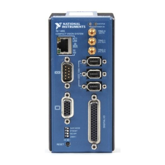
National Instruments CVS-1450 Series compact vision system. About the NI CVS-1450 Series NI CVS-1450 Series devices are easy-to-use, distributed, real-time imaging systems that acquire, process, and display images from IEEE 1394 cameras conforming to the IIDC 1394-based Digital Camera Specification, Version 1.30. - Page 10 Figure 1-1 shows the CVS-1450 Series front panel. 1 Power LED 2 Status LED 3 Isolated Digital Input 4 TTL Digital Outputs NI CVS-1450 Series User Manual NI 1454 Compact Vision System 5 IEEE 1394a Ports 6 TTL I/O and Isolated I/O...
-
Page 11: Available Camera Bandwidth
(4:2:2) 16-bits/pixel color 1024 × 768 16-bits/pixel mono © National Instruments Corporation Table 1-1. Available Camera Bandwidth Frames Video Format per Second Chapter 1 NI CVS-1450 Series Overview Maximum Number of Cameras for Simultaneous Operation NI CVS-1450 Series User Manual... -
Page 12: Software Overview
CVS-1450 device and the camera, such as IEEE 1394 bus communication and camera control. NI CVS-1450 Series User Manual NI Vision Builder for Automated Inspection (AI) 2.0 or later—Allows you to configure solutions to common inspection tasks LabVIEW Real-Time Module 7.0 or later with the Vision... -
Page 13: National Instruments Application Software
National Instruments Application Software This section describes National Instruments application software packages you can use to analyze and process the images you acquire with the CVS-1450 device. Vision Builder for Automated Inspection NI Vision Builder for Automated Inspection (AI) is configurable machine vision software that you can use to prototype, benchmark, and deploy machine vision applications. - Page 14 Vision Assistant. You can use them in LabVIEW to add functionality to the generated VI. For information about how to use the Vision Development Module with the LabVIEW Real-Time Module, refer to the IMAQ Vision for LabVIEW User Manual. NI CVS-1450 Series User Manual ni.com...
-
Page 15: Setup And Configuration
Setup and Configuration This chapter provides instructions for setting up the NI CVS-1450 Series hardware. This chapter also includes instructions for installing software, configuring an IP address, and acquiring an initial image using the application software. Required Items The following items are necessary for setting up the CVS-1450 device. -
Page 16: Software
Setup and Configuration ❑ To maintain signal integrity, the Ethernet cable length must be no longer than 100 m. Note Software ❑ ❑ Accessories National Instruments offers the following accessories for use with a CVS-1450 device. Hardware • • • • •... -
Page 17: Documentation
LabVIEW Real-Time Module Documents • • © National Instruments Corporation NI CVS-1450 Series User Manual NI 1450 Series Compact Vision System Digital I/O Help NI 1450 Series Compact Vision System Quick Start Guide NI Vision Builder for Automated Inspection Tutorial... -
Page 18: Safety Information
If the device is damaged, turn it off and do not use it until service-trained personnel can check its safety. If necessary, return the device to National Instruments for repair. Keep away from live circuits. Do not remove equipment covers or shields unless you are trained to do so. - Page 19 Do not exceed the maximum ratings for the device. Remove power from signal lines before connection to or disconnection from the device. National Instruments measurement products may be classified as either Caution Measurement Category I or II. Operate this device at or below the Measurement Category level specified in the hardware specifications.
-
Page 20: Setup Overview
Setup Overview Figure 2-1 illustrates the sequence for setting up and getting started with the CVS-1450 device. NI CVS-1450 Series User Manual Examples of Installation Category II are measurements performed on household appliances, portable tools, and similar products. Measurement Category III is for measurement performed in the building installation at the distribution level. -
Page 21: Before Getting Started: Connecting The Cvs-1450 Device To A Network
Obtain an IP address Acquiring an Image—This section explains how to use either Vision Builder AI or the LabVIEW Real-Time Module with the Vision Development Module to acquire an image. Chapter 2 Setup and Configuration NI CVS-1450 Series User Manual... -
Page 22: Setting Up The Hardware
CVS-1450 device DIP switches are in the OFF position. To connect an IEEE 1394 camera and a monitor to the CVS-1450 device, refer to Figure 2-2 while completing the following steps: NI CVS-1450 Series User Manual CVS-1450 device 24 VDC ±10%, 50 W power supply... -
Page 23: Wiring Power To The Cvs-1450 Device
CVS-1450 device. Plug the power cord into the power supply. Plug the power cord into an outlet. Chapter 2 Setup and Configuration 2 IEEE 1394 Cable section. Connecting the CVS-1450 section. If the images from the NI CVS-1450 Series User Manual... -
Page 24: Connecting To A Separate Main Supply
4-position power connector, shown in Figure 2-4. Ferrules are available from Phoenix Contact (part number 3200519). NI CVS-1450 Series User Manual 2 NI Desktop Power Supply Figure 2-3. Wiring Power to the CVS-1450 Device... - Page 25 Wire the common-mode signal (ground) output of the power supply to the common-mode signal input, labeled C, on the 4-position connector. Earth Ground Connection Connectors. 2-11 Chapter 2 Setup and Configuration 3 Power Supply Wires section of Chapter 3, LEDs, NI CVS-1450 Series User Manual...
-
Page 26: Connecting The Cvs-1450 Device To The Development Computer
1 Standard Ethernet Cable Connecting from the CVS-1450 Device to an Ethernet Hub 2 Standard Ethernet Cable Connecting from an Ethernet Hub to the Development Computer 3 Ethernet Hub or Other Network Port NI CVS-1450 Series User Manual Verify that the development computer is connected to the network and is powered on. -
Page 27: Vision Builder Ai: Setting Up The Development Computer
When the installation splash screen appears, click Install NI Vision Builder AI and follow the setup instructions. Insert the NI-IMAQ for IEEE 1394 Cameras CD into the CD-ROM drive. 2-13 Chapter 2 Setup and Configuration LabVIEW Real-Time NI CVS-1450 Series User Manual... -
Page 28: Configuring The Ip Address On The Cvs-1450 Device
The first and last characters must be alphanumeric. 10. Click OK to begin configuring the IP address and downloading NI CVS-1450 Series User Manual When the installation splash screen appears, click Install NI-IMAQ for IEEE 1394 Cameras, and follow the setup instructions. -
Page 29: Acquiring An Image In Vision Builder Ai
Builder for Automated Inspection Tutorial. Vision Builder AI: Setting up the Development LabVIEW and LabVIEW Real-Time Module software Vision Development Module software NI-IMAQ for IEEE 1394 Cameras driver software 2-15 Chapter 2 Setup and Configuration NI CVS-1450 Series User Manual... -
Page 30: Installing The Labview Real-Time Module, Vision Development Module, And Ni-Imaq For Ieee 1394 Cameras
Configuring the IP Address using the LabVIEW Real-Time Module To set up an IP address for the CVS-1450 device, complete the following steps: NI CVS-1450 Series User Manual Insert the LabVIEW CD into the CD-ROM drive. When the installation splash screen appears, click Install LabVIEW, and follow the setup instructions. -
Page 31: Downloading Software Onto The Cvs-1450 Device
When prompted, click Yes to restart the CVS-1450 device. This process takes several seconds. Launch LabVIEW by navigating to Start»Programs»National Instruments LabVIEW. Expand the Execution Target drop-down listbox, and click Select Target with Options. 2-17 Chapter 2 Setup and Configuration NI CVS-1450 Series User Manual... - Page 32 Now that you are acquiring images in LabVIEW, you can use the Vision Development Module and the installed CVS-1450 device drivers to process images and control inputs and outputs. NI CVS-1450 Series User Manual Enter the new IP address in the Machine Name/IP field, and click OK.
-
Page 33: Leds, Dip Switches, And Connectors
Refer to Appendix A, Troubleshooting, for information about troubleshooting LEDs. © National Instruments Corporation Connectors section provides signal names and descriptions for NI 1454 Compact Vision System Figure 3-1. POWER OK and STATUS LEDs STATUS POWER OK NI CVS-1450 Series User Manual... -
Page 34: Power Ok Led
The orange STATUS LED remains off under normal operating conditions and flashes a specific number of times to indicate error conditions or certain DIP switch settings. The STATUS LED remains lit if the CVS-1450 device detects an internal error. Refer to the for information about LED error indications. -
Page 35: Dip Switches
This section describes the SAFE MODE, IP RESET, NO APP, and USER 1 DIP switches on the CVS-1450 device. To enable a DIP switch, move it to the ON (left) position and then reset the CVS-1450 device by pressing the RESET button for at least two seconds. -
Page 36: Safe Mode Switch
SAFE MODE Switch To start the CVS-1450 device in Safe mode, move the SAFE MODE switch to the ON position and reset the CVS-1450 device. Use Safe mode to reconfigure TCP/IP settings and to download or update software from the development computer. -
Page 37: Ip Reset Switch
USER 1 Switch (LabVIEW Real-Time Module Users) The USER 1 switch is user-configurable and has no default functionality. You can use the RT Read Switch VI to read the USER 1 switch state and perform a custom action based on the current switch state position. -
Page 38: Connectors
The isolation provided by the CVS-1450 device is intended to prevent ground Caution loops that could introduce noise into the system. This isolation does not provide safety isolation. NI CVS-1450 Series User Manual External Connectors 4-position power Main power and power for isolated outputs... -
Page 39: Earth Ground Connection
Figure 3-4. Power Connector Table 3-2. Power Connector Terminals Terminal Main power (24 VDC ±10%) Common-mode signal Viso Isolated power (5 to 30 VDC) Ciso Isolated common-mode signal LEDs, DIP Switches, and Connectors POWER Description NI CVS-1450 Series User Manual... -
Page 40: Ieee 1394
CVS-1450 device and a VGA monitor. Use any standard 15-pin VGA cable to access the VGA connector. Figure 3-6 shows the location and pinout of the VGA connector. Table 3-3 lists and describes the VGA connector signals. NI CVS-1450 Series User Manual POWER (5-30VDC) (24VDC ±10%) 2 Power Connector Figure 3-5. - Page 41 CVS-1450 device main power Common-mode signal of the CVS-1450 device main power Common-mode signal of the CVS-1450 device main power +5 V +5 V LEDs, DIP Switches, and Connectors NI 1454 Compact Vision System Signal Description NI CVS-1450 Series User Manual...
-
Page 42: Com1
The Serial Port VIs access COM1 as Port 0. Note Figure 3-7 shows the location and pinout of the COM1 DSUB 9-pin connector. Table 3-4 lists and describes the COM1 signals. NI CVS-1450 Series User Manual Table 3-3. VGA Connector Signals (Continued) Signal Name Common-mode signal of the... -
Page 43: Ethernet
Data Carrier Detect Receive Data Transmit Data Data Terminal Ready Common-mode signal of the CVS-1450 device main power Data Set Ready Ready to Send Clear to Send Ring Indicator 3-11 LEDs, DIP Switches, and Connectors Signal Description NI CVS-1450 Series User Manual... -
Page 44: Trig 0
The TRIG 0 isolated input on the CVS-1450 device provides connection to external devices, such as proximity sensors and start/stop buttons. For easy connection to the TRIG 0 input, use the National Instruments SMB 111 coaxial cable (part number 763422-01). - Page 45 Common-mode signal of the CVS-1450 device main power TTL Output 0 Watchdog timer output TTL Output 1 Pulse generator output 3-13 LEDs, DIP Switches, and Connectors Alternate Function General-purpose input — General-purpose output General-purpose output NI CVS-1450 Series User Manual...
- Page 46 44-Pin DSUB on 37-Pin CVS-1450 Terminal Device Block Pin Number Pin Number NI CVS-1450 Series User Manual Signal Name Primary Function Common-mode signal of the CVS-1450 device main power TTL Output 2 Pulse generator output TTL Output 3 Pulse generator output...
- Page 47 General-purpose input 3-15 LEDs, DIP Switches, and Connectors Alternate Function — — — — — — — — — — — — Pulse generator trigger input — General-purpose input General-purpose input — General-purpose input General-purpose input NI CVS-1450 Series User Manual...
- Page 48 Table 3-5. 44-Pin DSUB and 37-Pin Terminal Block Connector Signals (Continued) 44-Pin DSUB on 37-Pin CVS-1450 Terminal Device Block Pin Number Pin Number NI CVS-1450 Series User Manual Signal Name Primary Function Ciso Isolated common-mode signal ISO Input 10 General-purpose input ISO Input 11 User shutdown...
-
Page 49: Digital I/O Functionality
To quickly launch the digital I/O help from a LabVIEW example, press <F1>. TTL and Isolated Inputs and Outputs This section describes the TTL and Isolated I/O functions available on the CVS-1450 device. © National Instruments Corporation Program Files\National Instruments\NI 1450 Series\Docs > < LabVIEW \examples\NI 1450 NI CVS-1450 Series User Manual... -
Page 50: Ttl Inputs And Outputs
The isolated outputs have current-limiting protection circuitry. If this circuitry is tripped, you can re-enable the outputs by restarting the CVS-1450 device or by toggling the output state in the software. NI CVS-1450 Series User Manual Table 4-1. TTL Inputs and Outputs Number... -
Page 51: I/O For Normal Operation
ISO Input 9 ISO Input 10 ISO Output 0 ISO Output 1 ISO Output 2 ISO Output 3 Chapter 4 Digital I/O Functionality 44-Pin DSUB on CVS-1450 37-Pin Device Terminal Block Pin Number Pin Number — — NI CVS-1450 Series User Manual... -
Page 52: Timed Pulse Output
The assertion edge is configurable based on the trigger polarity parameter. It then generates one pulse and rearms to NI CVS-1450 Series User Manual ni.com... - Page 53 10 µs to 4,294,967,295 µs. Trigger Polarity Each pulse generator can be individually configured for rising or falling edge triggering. Even if multiple pulse generators are using the same trigger, each can have different polarities. © National Instruments Corporation NI CVS-1450 Series User Manual...
-
Page 54: Quadrature Encoder
Each isolated input can change at a maximum rate of 100 kHz, making the maximum encoder rate 400,000 counts/s. The quadrature encoder can also be used as a timebase for the pulse generation delay. NI CVS-1450 Series User Manual Delay Width Trigger Pulse Figure 4-2. -
Page 55: Product Selection Port
The product selection port consists of a group of five isolated digital inputs that the software running on the CVS-1450 device reads simultaneously. You can program the CVS-1450 device to switch between up to 32 (2 inspection sequences for different parts on an assembly line. -
Page 56: General-Purpose I/O
NI CVS-1450 Series User Manual Table 4-3. Product Selection Port Function ISO Input 5... -
Page 57: I/O For Fault Conditions
• The behavior of the CVS-1450 device in the event of a fault condition is dependent on configuration settings of the SAFE MODE DIP switch and the software-enabled Shutdown mode. Table 4-4 summarizes how user configuration affects the behavior of the CVS-1450 device in the event of a fault condition. -
Page 58: Shutdown
Each TTL output is configurable to drive high, drive low, or 3-state, and each isolated output is on/off configurable. Shutdown mode is unavailable when the SAFE MODE DIP switch is turned on. Refer to Table 4-4 for a summary of how user configuration affects the shutdown condition. -
Page 59: Overheat
System Shutdown—This option halts the CVS-1450 device operation and turns the POWER OK LED red. If Shutdown mode is enabled, the outputs go to the user-defined shutdown states. 4-11 Chapter 4 Digital I/O Functionality NI CVS-1450 Series User Manual... -
Page 60: Considerations When Connecting The Digital I/O
Figure 4-6. Caution Do not draw more than 100 mA from 24 V or 30 V isolated outputs. Do not draw more than 50 mA from 5 V isolated outputs. NI CVS-1450 Series User Manual Sourcing Output Device... -
Page 61: Protecting Inductive Loads
Figure 4-7 shows an example of using an external flyback diode to protect inductive loads. © National Instruments Corporation CVS-1450 device Figure 4-6. Example of Connecting an Isolated Output to an External Load 4-13 Chapter 4 Digital I/O Functionality Viso Digital Output Load Ciso NI CVS-1450 Series User Manual... -
Page 62: Transmission Line Effects
RG-179, to connect to the SMB connectors. Figure 4-8 shows connections to the 44-pin DSUB connector and the TRIG 0 SMB connector that minimize transmission line effects. NI CVS-1450 Series User Manual CVS-1450 device Figure 4-7. Example of Using an External Flyback Diode for Inductive Loads... -
Page 63: Typical System Setup
62 kΩ TTL IN(0) Figure 4-8. Example Connections equal to 118 Ω, as shown in Figure 4-8. 4-15 Chapter 4 Digital I/O Functionality TRIG 1 RG-179 Coaxial Cable Receiving Equipment 44-Pin DSUB Receiving Equipment Transmitting Equipment NI CVS-1450 Series User Manual... - Page 64 TRIG 1 TRIG 2 Figure 4-9 shows a typical single-camera setup. 1 Lighting Control Unit 2 Lighting Ring NI CVS-1450 Series User Manual Table 4-5. Typical Single-Camera System Setup Signal Type Isolated input Timed pulse TTL output Timed pulse TTL output...
-
Page 65: Deployment
As with all Ethernet devices, you can connect multiple CVS-1450 devices to the same network, as shown in Figure 5-1. © National Instruments Corporation Figure 5-1. Multiple CVS-1450 Devices Connected to the Same Network NI CVS-1450 Series User Manual... - Page 66 For local monitoring of the inspection, you can connect a monitor directly to the Video Out connector on the CVS-1450 device, as shown in Figure 5-3. NI CVS-1450 Series User Manual Figure 5-2. Serial Number and MAC Address Label on the CVS-1450 Device ni.com...
- Page 67 Chapter 5 Deployment Figure 5-3. CVS-1450 Device Connected to a Monitor At any time, you can reconnect the host machine to the CVS-1450 device and remotely monitor progress. © National Instruments Corporation NI CVS-1450 Series User Manual...
-
Page 68: Appendix A Troubleshooting
The grade of cable you are using may be insufficient for the speed of your network, or you may be using the wrong type of Ethernet cable. Use a straight-through cable when connecting to network hardware. Use a crossover cable to connect directly to the development computer. NI CVS-1450 Series User Manual... - Page 69 CVS-1450 device IP address. The DIP switch settings on the CVS-1450 device may be invalid, such as all switches set to the ON position. Change the DIP switch settings and reset the CVS-1450 device by pressing the RESET button on the CVS-1450 device for at least two seconds.
- Page 70 Processor overheat – Make sure you are operating the CVS-1450 device in compliance with the temperature specifications in Appendix B, Specifications. Configuration Settings and Appendix A Troubleshooting Effects, for more NI CVS-1450 Series User Manual...
-
Page 71: Led Error Indications
If a runaway startup application causes the CVS-1450 device to become unresponsive, power off the CVS-1450 device and then restart it with either the NO APP switch or the SAFE MODE switch in the ON position. Restarting the CVS-1450 device with the NO APP switch enabled prevents any VIs from running at startup. - Page 72 Repeat the firmware upgrade process. The CVS-1450 device is in Safe mode. The CVS-1450 device has detected an unrecoverable error. Contact National Instruments for assistance. Appendix A Troubleshooting Error Condition NI CVS-1450 Series User Manual...
-
Page 73: Power Requirements
Specifications This appendix lists the specifications of the NI CVS-1450 Series. These specifications are typical at 25 °C, unless otherwise noted. Power Requirements Main supply voltage... 24 VDC ±10% Isolated supply Memory SDRAM ... 128 MB Nonvolatile storage Processor CVS-1454... Intel Celeron 400 MHz processor CVS-1455... - Page 74 Minimum pulse detected ...500 ns Power-on state ...Input (high-impedance) TTL Outputs Number of channels...10 Output voltage range ...0 V to 5 V Maximum pulse rate ...2 MHz NI CVS-1450 Series User Manual Ethernet auto-negotiated Level Minimum 2.2 V ), at 5 mA —...
- Page 75 Viso... 1.2 V at 100 mA 5 V isopower ... 50 mA, maximum 24 V isopower ... 100 mA, maximum 30 V isopower ... 100 mA, maximum Appendix B Specifications 14 mA, maximum resistance 100 kΩ) NI CVS-1450 Series User Manual...
-
Page 76: Physical Characteristics
Humidity ...10% to 90% RH, noncondensing Pollution Degree ...2 Operating shock (IEC 68-2-27) ...50 g, 6 ms half sine, Operating vibration NI CVS-1450 Series User Manual Mounting Information, for dimensional drawings of Vertical mounting position ...0 °C to 55 °C All other positions ...0 °C to 45 °C... -
Page 77: Electromagnetic Compatibility
, search by model number or product line, and click the , search by model number or product line, and click the Appendix B Specifications FCC Part 15A above 1 GHz Table 1 (Class A) Compliant NI CVS-1450 Series User Manual... - Page 78 This appendix provides the information necessary to create a custom mount for the NI CVS-1450 Series. If you do not want to create a custom mount, a panel and DIN rail mount kit for the CVS-1450 Series is available from National Instruments (part number 189154-01). Mounting the CVS-1450 Series If you want to create a custom mount, Figures C-1–C-4 provide...
- Page 79 You can ground the CVS-1450 device to your mount by connecting a grounding wire Note to the grounding lug on the CVS-1450 device. Refer to the section of Chapter 3, grounding lug. NI CVS-1450 Series User Manual 127.25 mm (5.010 in.) Figure C-2. Side View of the CVS-1450 Series with Dimensions 62.56 mm (2.463 in.)
- Page 80 CVS-1450 Series. © National Instruments Corporation 76.2 mm (3.00 in.) 50.8 mm (2.00 in.) 76.2 mm (3.00 in.) Figure C-4. Space and Cabling Clearance for the CVS-1450 Series Appendix C Mounting Information 50.8 mm (2.00 in.) NI CVS-1450 Series User Manual...
- Page 81 Complete the following steps to secure the CVS-1450 device to your mount: NI CVS-1450 Series User Manual Align the screw holes of your mounting bracket with the four holes on the back of the CVS-1450 device. Figure C-1 shows the location of the mounting holes on the CVS-1450.
- Page 82 Technical Support and Professional Services Visit the following sections of the National Instruments Web site at ni.com • • • • © National Instruments Corporation for technical support and professional services: Support—Online technical support resources at include the following: –...
- Page 83 Worldwide Offices section of office Web sites, which provide up-to-date contact information, support phone numbers, email addresses, and current events. NI CVS-1450 Series User Manual Calibration Certificate—If your product supports calibration, you can obtain the calibration certificate for your product at ni.com/calibration...
- Page 84 Real-Time target. falling edge The digital signal transition from the high state to the low state. IEEE Institute of Electrical and Electronics Engineers. A standard-setting body. © National Instruments Corporation Value –6 –3 NI CVS-1450 Series User Manual...
- Page 85 Light-emitting diode. Media access control. The MAC address uniquely identifies each unit connected to a network. NI-IMAQ Driver software for National Instruments image acquisition (IMAQ) hardware. Programmable Logic Controller. An industrial computer used for factory automation, process control, and manufacturing systems.
- Page 86 UDP is for low-overhead transmissions. Volts direct current. Virtual Instrument. A combination of hardware and/or software elements, typically used with a PC, that has the functionality of a classic stand-alone instrument. © National Instruments Corporation NI CVS-1450 Series User Manual Glossary...
- Page 87 1-1 digital I/O 44-pin DSUB, 3-12 cable, D44, 3-12 connection considerations, 4-12 connector (table), 3-6 connector pinout (figure), 3-13 connector signals (table), 3-13 examples (LabVIEW Real-Time Module), 4-1 external load, wiring, 4-12 general-purpose, 3-12 NI CVS-1450 Series User Manual...
- Page 88 (table), 3-6 examples (NI resources), D-1 external load, wiring, 4-12 flyback diode, inductive loads (figure), 4-14 flyback voltage, flyback diode, 4-13 NI CVS-1450 Series User Manual grounding lug, 3-8 hardware connection accessories, 2-2 basic components, 2-8 camera, monitor, 2-8...
- Page 89 2-10 terminals (table), 3-7 wiring power, 2-9 figure, 2-10 product selection port, 4-7 table, 4-8 programming examples (NI resources), D-1 pulse delay, 4-5 pulse modes, 4-5 pulse width, 4-5 quadrature encoder, 4-6 NI CVS-1450 Series User Manual Index...
- Page 90 B-1 safety, B-5 inputs, B-2 outputs, B-2 STATUS LED, 3-2 error indications (table), A-4 NI CVS-1450 Series User Manual subnet, 2-7, 5-2 support, technical, D-1 technical support, D-1 terminal block, 37-pin (table), 3-13 timed pulse output, initiating, 4-4...
- Page 91 Vision Development Module configuring IP address, 2-16 description, 1-5 image acquisition, 2-17 installing, 2-15 Web resources, D-1 © National Instruments Corporation NI CVS-1450 Series User Manual Index...