Fusion MS-RA70 Installation Instructions Manual
Hide thumbs
Also See for MS-RA70:
- Quick start manual (17 pages) ,
- Owner's manual (12 pages) ,
- Manual (8 pages)
Table of Contents
Advertisement
Fusion
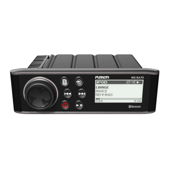
MS-RA70/MS-RA70N
®
Installation Instructions
Important Safety Information
Failure to follow these warnings and cautions could result in
personal injury, damage to the vessel, or poor product
performance.
See the Important Safety and Product Information guide in the
product box for product warnings and other important
information.
This device must be installed according to these instructions.
Disconnect the vessel's power supply before beginning to install
this product.
Before applying power to this product, make sure it has been
correctly grounded, following the instructions in the guide.
Always wear safety goggles, ear protection, and a dust mask
when drilling, cutting, or sanding.
When drilling or cutting, always check what is on the opposite
side of the surface.
You must read all installation instructions before beginning the
installation. If you experience difficulty during the installation,
contact Fusion Product Support.
What's In the Box
• DIN mounting plate
• Four 8-gauge, self-tapping screws
• Power and speaker wiring harness
• Auxiliary-in, line-out, and subwoofer-out wiring harness
Tools Needed
• Phillips screwdriver
• Electric drill
• Drill bit (size varies based on surface material and screws
used)
• Rotary cutting tool or jigsaw
• Marine sealant (optional)
Mounting Considerations
• The stereo can be mounted on a flat surface or in a single-
DIN opening as a replacement for an existing stereo.
• The stereo must be mounted in a location that allows open
airflow around the rear of the stereo for heat ventilation.
• If you are installing the stereo in a location that may be
exposed to water, it must be mounted within 45 degrees of
the horizontal plane.
December 2015
®
WARNING
CAUTION
NOTICE
• If you are installing the stereo in a location that may be
exposed to water, the cable should have a drip loop to allow
water to drip down off the cable and avoid damage to the
stereo.
• If you need to mount the stereo outside a boat, it must be
mounted in a location far above the waterline, where it is not
submerged.
• If you need to mount the stereo outside a boat, it should be
mounted in a location where it cannot be damaged by docks,
pilings, or other pieces of equipment.
• To avoid interference with a magnetic compass, the stereo
should be installed at least 15 cm (5.9 in.) away from a
compass.
Mounting the Stereo in a New Location
Be careful when cutting the hole to mount the stereo. There is
only a small amount of clearance between the case and the
mounting holes, and cutting the hole too large could
compromise the stability of the stereo after it is mounted.
Before you can mount the stereo in a new location on the
mounting surface, you must select a location in accordance with
the mounting considerations.
1
Trim the template and make sure it fits at the mounting
location.
2
Adhere the template to the mounting surface.
3
Using a drill bit appropriate for the mounting surface, drill a
hole inside the corner of the dashed line on the template to
prepare the mounting surface for cutting.
4
Using a rotary-cutting tool, cut the mounting surface along
the inside of the dashed line on the template.
5
Place the stereo in the cutout to test the fit.
6
If necessary, use a file and sandpaper to refine the size of
the cutout.
7
After the stereo fits correctly in the cutout, ensure the
mounting holes on the stereo line up with the pilot holes on
the template.
8
If the mounting holes on the stereo do not line up, mark the
new pilot-hole locations.
9
Using an appropriately sized drill bit for the mounting surface
and screw type, drill the pilot holes.
10
Remove the template from the mounting surface.
11
Make the necessary wiring connections
Considerations, page
12
Place the mounting gasket on the back of the stereo
Printed in Taiwan
NOTICE
(Connection
2).
190-01946-02_0B
.
Advertisement
Table of Contents

Subscribe to Our Youtube Channel
Related Manuals for Fusion MS-RA70


Summary of Contents for Fusion MS-RA70
- Page 1 You must read all installation instructions before beginning the Mounting the Stereo in a New Location installation. If you experience difficulty during the installation, contact Fusion Product Support. NOTICE Be careful when cutting the hole to mount the stereo. There is...
- Page 2 AUX when a call is received and the phone connects this wire to ground. This functionality can be configured from the settings menu. Fusion MS-RA70/MS-RA70N Installation Instructions...
- Page 3 Do not connect the wiring harness to the stereo until after all Powered subwoofer of the bare wire connections have been made. Connect the black wire to the negative (-) battery terminal. NMEA 2000 System Wiring Diagram NOTE: NMEA 2000 is available on Fusion MS-RA70N models only. Fusion MS-RA70/MS-RA70N Installation Instructions...
-
Page 4: Specifications
• Keep the original sales receipt, or a photocopy, in a safe FM frequency 50 kHz 200 kHz 50 kHz place. step Software Updates For best results, you should update the software in all Fusion devices at the time of installation to ensure compatibility. Fusion MS-RA70/MS-RA70N Installation Instructions... - Page 5 Software updates and instructions are available on your device product page. Garmin , the Garmin logo, Fusion , and the Fusion logo are trademarks of Garmin Ltd. or ® ® its subsidiaries, registered in the USA and other countries. These trademarks may not be used without the express permission of Garmin.
- Page 6 © 2015 Garmin Ltd. or its subsidiaries www.garmin.com/support...
Need help?
Do you have a question about the MS-RA70 and is the answer not in the manual?
Questions and answers