
Related Manuals for C-Nav 1000 R4


Summary of Contents for C-Nav 1000 R4
- Page 1 Installation Manual C-Nav® World DGPS 730 East Kaliste Saloom Rd. Lafayette, La. 70508 USA Tel: +1 337 210 0000 Fax: +1 337 261 0192 E-mail: cnav.support@cnavgps.com...
- Page 2 C-Nav office or dealer nearest you: ® For technical support queries, including subscription, service, hardware and software issues, contact C-Nav Support: E-mail: cnav.support@cnavgps.com Phone: +1 337 210 0000 (24/7 support) For general queries, including requests for DGPS information, publications, billing and...
- Page 3 Standard magnetic Steering magnetic compass compass R4 Display 0.6 m 0.3 m R4 Navigation Sensor 0.6 m 0.4 m (GPS and DGPS) Contact Information For installation, service and technical support please contact C-Nav Support: cnav.support@cnavgps.com, or by phone: +1 (337) 210-0000...
-
Page 4: Table Of Contents
CONTENTS Page i TABLE OF CONTENTS INTRODUCTION About this Manual System Overview UNPACKING THE EQUIPMENT INSTALLATION CABLES MOUNTING Mount the R4 Display 4.1.1 Location 4.1.2 Physical Size and Mechanical Drawing 4.1.3 Gimbal Mounting 4.1.4 Panel Mounting 4.1.5 Cabling 4.1.6 Power Supply Mount R4 Navigation Sensor 4.2.1 Location... - Page 5 CONTENTS Page ii Viewing Active Alarms GPS Connection Lost Troubleshooting Position Data Lost Troubleshooting System Functional Check Specifying Port Communication Rates Configuring Output Sentences 6.10 Adjusting System Settings SERIAL COMMUNICATION INTERFACES Electrical Characteristics R4 Display 7.1.1 Output Drive Capacity 7.1.2 Input Load 7.1.3 Termination...
- Page 6 CONTENTS Page iii LIST OF FIGURES Figure 1-1: R4 Navigation System overview Figure 4-1: Mechanical drawing R4 Display Figure 4-2: Gimbal mount clearance area Figure 4-3: Gimbal mount Figure 4-4: Panel mount frame dimensions Figure 4-5: Clearance distance behind the display Figure 4-6: Panel mount hole dimensions Figure 4-7: Panel mounting R4 Display Figure 4-8: R4 Display panel mounted...
-
Page 7: Introduction
INTRODUCTION Page 1 INTRODUCTION About this Manual This manual, together with the Operator’s Manual, provides in-depth information to facilitate installation of the C-Nav1000 R4 Navigation System The C-Nav1000 R4 Navigation System is available in two system configurations: GPS and DGPS. This manual is valid for both configurations. -
Page 8: System Overview
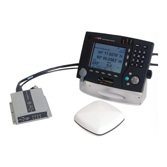
INTRODUCTION Page 2 System Overview Figure 1-1 shows an overview of the R4 Navigation System. The R4 Navigation System is available in two configurations: GPS and DGPS. Both configurations feature an R4 Display. The GPS configuration also features an R4 GPS Navigation Sensor and an MGA-2 GPS antenna, while the DGPS configuration features an R4 DGPS Navigation Sensor and an MGL- 4 combined GPS/Beacon antenna. -
Page 9: Unpacking The Equipment
UNPACKING THE EQUIPMENT Page 3 UNPACKING THE EQUIPMENT The R4 Navigation System is made up of parts as listed below. Common Equipment The following equipment is required in both GPS and DGPS configuration. Name Part number Qty. SAA7000 108-035 1 R4 Display Unit SAA7000 108-132 1 R4 Display Power Cable... -
Page 10: Installation Cables
INSTALLATION CABLES Page 4 INSTALLATION CABLES The following cables are needed for installation of the R4 Navigation System. R4 Display Signal Cable Type: 6-Pair x 0,25 mm Shield Length: Connector: ConXall, Maxi-Con-18pin (male) Marking: 7000 108-133 R4 Display Power Cable Type: 3 x 0.5 mm Length:... -
Page 11: Mounting
MOUNTING Page 5 MOUNTING When mounting the R4 Navigation System it is recommended to follow the steps as described in this Installation Manual. Details of the installation procedure are found in the coming sections of the Installation Manual. Recommended installation steps: 1. -
Page 12: Mount The R4 Display
MOUNTING Page 6 Mount the R4 Display 4.1.1 Location The R4 Display should be mounted close to the position from which the ship is normally operated, preferably on the bridge console close to the conning position. When mounting the R4 Display please consider the following: •... -
Page 13: Physical Size And Mechanical Drawing
MOUNTING Page 7 4.1.2 Physical Size and Mechanical Drawing Figure 4-1: Mechanical drawing R4 Display 4.1.3 Gimbal Mounting 1. Determine where to install the R4 Display. The R4 Display can be mounted horizontally or vertically. Make sure there is enough space around the R4 Display, see Figure 4-2 below. -
Page 14: Figure 4-2: Gimbal Mount Clearance Area
MOUNTING Page 8 Figure 4-2: Gimbal mount clearance area 2. Fasten the gimbal mount on a flat surface with three screws, see Figure 4-3 below. The type of screws has to be chosen considering the panel material. Note that the slots on the end of the gimbal mount have to face the direction in which the R4 Display is to be mounted. -
Page 15: Figure 4-3: Gimbal Mount
MOUNTING Page 9 Figure 4-3: Gimbal mount 3. Slide the R4 Display into the slots on the end of the gimbal mount. Secure the R4 Display onto the gimbal mount using the locking knobs without over-tightening. 4. Attach the signal cable (18 pin plug) and the power cable (3 pin socket), as described in section 4.1.5. -
Page 16: Panel Mounting
MOUNTING Page 10 4.1.4 Panel Mounting 1. Determine where to install the R4 Display, see Figure 4-4 below for dimensions. Make sure that there is enough depth behind the panel, see Figure 4-5. Please note that the signal cable has a maximum bending radius of 10 centimeters. -
Page 17: Figure 4-6: Panel Mount Hole Dimensions
MOUNTING Page 11 Figure 4-6: Panel mount hole dimensions 3. Place the panel mount frame in the rectangular hole and mark the location of the four screw holes in the bedding. 4. Remove the panel mount frame and drill four screw holes where marked in the panel. -
Page 18: Figure 4-7: Panel Mounting R4 Display
MOUNTING Page 12 Figure 4-7: Panel mounting R4 Display Figure 4-8: R4 Display panel mounted... -
Page 19: Cabling
MOUNTING Page 13 4.1.5 Cabling Use the cables included, one for power supply and one signal cable for connecting the display to the R4 Navigation Sensor, external systems and sensors. Note that the signal cable requires a minimum bending radius of 10 Connect the R4 Display Power Cable, marked “7000 108-132”, and the R4 Display Signal Cable, marked “7000 108-133”, to the corresponding ConXall connectors on the back of the R4 Display. -
Page 20: Mount R4 Navigation Sensor
MOUNTING Page 14 Mount R4 Navigation Sensor 4.2.1 Location When mounting the R4 Navigation Sensor please consider the following: • Mount the unit so that the LEDs can be observed if needed for troubleshooting purposes. • The temperature and humidity should be moderate and stable, +15ºC to +35ºC. -
Page 21: Clearance Area
MOUNTING Page 15 4.2.2 Clearance Area Leave a clearance around the R4 Navigation Sensor to facilitate service and installation. See recommended clearance area in Figure 4-10 below. Figure 4-10: Clearance area for R4 Navigation Sensor... -
Page 22: Physical Size And Mechanical Drawing
MOUNTING Page 16 4.2.3 Physical Size and Mechanical Drawing See figure below. Figure 4-11: R4 Navigation Sensor mechanical drawing 4.2.4 Cabling Use the included R4 Power and Data cable, marked “7000 109-011”, to connect to the R4 Navigation Sensor to the power source, the R4 Display and any external systems or sensors. -
Page 23: Power Supply
MOUNTING Page 17 connector to the female 18 pin connector on the back of the R4 Navigation Sensor. Wire the open end of the cable as described in section 5.1 and Appendix [A.8]. Connect the antenna to the R4 Navigation Sensor, following the instructions in section 4.3. -
Page 24: Cabling
MOUNTING Page 18 The MGA-2 and MGL-4 uses a 1-14-UNS thread for mounting. Mount the antenna on a standard US 1” 14 thread pipe or other standard antenna mount (not included). Note: Antennas threaded onto a mount should be tightened only by hand. -
Page 25: Wiring Cable Connections
WIRING CABLE CONNECTIONS Page 19 WIRING CABLE CONNECTIONS A detailed installation wiring diagram for the R4 Navigation System is available in Appendix [A.8]. This diagram includes cable connections for the R4 Navigation Sensor, R4 Display, power supply and RS422 ports. The diagram also illustrates how to correctly connect shield of external equipment. -
Page 26: System Port
WIRING CABLE CONNECTIONS Page 20 5.1.1 System Port The System port interface is used to connect to the R4 Display, via the Display’s R4 Sensor port. The TX lines of the port shall be connected to the RX lines of the R4 Sensor port on the Display, and the RX lines of the System port shall be connected to the TX lines of the R4 Sensor port. -
Page 27: Alarm Acknowledge Binary Port
WIRING CABLE CONNECTIONS Page 21 5.1.6 Alarm Acknowledge Binary Port The Alarm Acknowledge binary port is used to acknowledge all active alarms. The “Alarm Ack” wire should be connected to Signal GND via a normally open momentary switch, capable of handling a 1 mA current. Except for the switch, no extra circuits are needed. -
Page 28: Power Wires
WIRING CABLE CONNECTIONS Page 22 Figure 5-2: R4 Display Signal cable and Power cable description 5.2.1 Power Wires Connect the Power + and the Power - wires to a 24 VDC power supply. 5.2.2 R4 Sensor Port The R4 Sensor port is used to connect to the R4 Navigation Sensor unit. The TX lines of the port shall be connected to the RX lines of the System port on the R4 Navigation Sensor. -
Page 29: Front Plug Port (Not Used)
WIRING CABLE CONNECTIONS Page 23 It is up to the user to configure the types of messages that shall be sent and received on the port, as well as the baud rate used for communication. This port may also be connected to the User Port 3 of an external R4 navigation system in order to synchronize database and settings in a dual redundant system installation. -
Page 30: System Configuration And Settings
SYSTEM CONFIGURATION AND SETTINGS Page 24 SYSTEM CONFIGURATION AND SETTINGS This section describes how to start up the system, verify its functionality and, if needed, adjust the R4 Navigation System to its usage environment. All parameters are set via the R4 Display. To set parameters, follow the steps as described in the following sections. -
Page 31: Status Leds
SYSTEM CONFIGURATION AND SETTINGS Page 25 character in a text field press once for the first character associated with the key, twice for the second character and so on. Provides access to additional pages of function keys in certain views. PAGE A small arrow in the bottom right corner of the display indicates that more pages are available. -
Page 32: Viewing Active Alarms
SYSTEM CONFIGURATION AND SETTINGS Page 26 When the system is started, there may be some alarms displayed depending on which sensors that have been connected to the system. If any alarms are displayed, take notice of the alarms displayed and then acknowledge them by pressing the key until the alarms are not displayed any more. -
Page 33: Position Data Lost Troubleshooting
SYSTEM CONFIGURATION AND SETTINGS Page 27 2. Verify that power is correctly applied to the R4 Navigation Sensor, indicated by the red LED marked “PWR” being lit on the Sensor. If not, check the wiring of the positive and negative power wires. 3. - Page 34 SYSTEM CONFIGURATION AND SETTINGS Page 28 1. Press key and then press function key followed by MODE NAVIGATE . The Position view should be displayed, as illustrated below: Position 2. Verify that latitude and longitude are displayed, and that an icon in the status bar indicates that valid position information is received.
-
Page 35: Specifying Port Communication Rates
SYSTEM CONFIGURATION AND SETTINGS Page 29 The SNR column shows the SNR for each received satellites signal. A good antenna installation should receive three or more satellites with SNR values above 50. If few satellite signals are received, and / or the received signals have low SNR ratings, this could indicate that the GPS reception is poor and that the position of the antenna needs to be adjusted. - Page 36 SYSTEM CONFIGURATION AND SETTINGS Page 30 2. Press the key, and then function key The I/O PAGE I/O Config. Configuration view is shown. 3. Press function key . The Port Rate Configuration view Port Rate Config is shown, as illustrated below. 5.
-
Page 37: Configuring Output Sentences
SYSTEM CONFIGURATION AND SETTINGS Page 31 Configuring Output Sentences The sentences that are sent on each of the user ports are configurable on sentence level. The sentences that can be output from the R4 Navigation System are listed in section 7.4. Each sentence configured for output will increase the load on the port. -
Page 38: Adjusting System Settings
SYSTEM CONFIGURATION AND SETTINGS Page 32 5. Select the sentence to modify the sentence send rate for using ∧ ∨ , and press . A drop-down box is displayed, ENTER with the send rates valid for the selected sentence. See illustration to the right. Use ∧ ∨ to select the entry in the drop-down box that best represents your desired rate, and then press... -
Page 39: Serial Communication Interfaces
SERIAL COMMUNICATION INTERFACES Page 33 SERIAL COMMUNICATION INTERFACES This section describes the electrical characteristics of the serial interfaces in the R4 Navigation System, as well as the supported IEC 61162 input and output sentences. Electrical Characteristics R4 Display 7.1.1 Output Drive Capacity Each talker output can have a maximum of 10 listeners drawing 2.0 mA. -
Page 40: Electrical Characteristics R4 Navigation Sensor
SERIAL COMMUNICATION INTERFACES Page 34 Figure 7-2: R4 Display serial interface output schematics Electrical Characteristics R4 Navigation Sensor 7.2.1 Output Drive Capacity Each talker output can have a maximum of 20 listeners drawing 2.0 mA. 7.2.2 Input Load Each listener draws less than 2 mA @ 2 V input voltage. 7.2.3 Termination If needed, 1 kΩ... -
Page 41: Figure 7-3: R4 Navigation Sensor Serial Interface Input Schematics
SERIAL COMMUNICATION INTERFACES Page 35 Figure 7-3: R4 Navigation Sensor serial interface input schematics Figure 7-4: R4 Navigation Sensor serial interface output schematics... -
Page 42: Input Sentences
SERIAL COMMUNICATION INTERFACES Page 36 Input Sentences The serial interfaces of the R4 Navigation System supports receiving and interpreting the input sentences described in Table 7-1 below. The user can configure which messages to receive and interpret and which port to receive them on. -
Page 43: Output Sentences
SERIAL COMMUNICATION INTERFACES Page 37 Output Sentences The serial interfaces of the R4 Navigation System supports transmission of the sentences described in Table 7-2 and Table 7-3 below. All sentences can be transmitted on User Port 1 and 2, while User Port 3 supports a limited set of sentences. - Page 44 SERIAL COMMUNICATION INTERFACES Page 38 Table 7-3. Supported navigation output sentences Sentence Description Port 1 & 2 Port 3 Alarm state Note 1 Note 1 Waypoint arrival alarm 1 Hz Heading/track controller (Autopilot) 1 Hz sentence B Bearing, origin to destination 1 Hz Bearing and distance to waypoint (great 1 Hz...
-
Page 45: Technical Specifications
TECHNICAL SPECIFICATIONS Page 39 TECHNICAL SPECIFICATIONS R4 Display PHYSICAL Dimensions: Height: 207 mm Width: 270 mm Depth: 102 mm Weight: 1.1 kg POWER Input Voltage: 24 V DC (22 to 31V DC) Current need: Nom 0.35 A (8.4 W) @ 24 VDC input ENVIRONMENTAL -15 °... - Page 46 TECHNICAL SPECIFICATIONS Page 40 ENVIRONMENTAL -30 ° C to +70 ° C (Operational) Temperature: -40 ° C to +80 ° C (Storage) Vibrations: IEC 60945 ed. 4. EMC: IEC 60945 ed. 4 Compass Safe Distance: 60 cm (for standard magnetic compass) and 40 cm (for steering magnetic compass) INTERNAL GPS RECEIVER Type:...
-
Page 47: Appendices
APPENDICES Page 41 APPENDICES [ A.1 ] Reference Documents [ A.2 ] Interpretations of IEC 61162-1 Sentences [ A.3 ] Other NMEA Sentences [A.4] Proprietary Sentences (PSTT) [A.5] Front Plug Port Characteristics [A.6] Sensor Antenna Cable Selector [A.7] Glossary [A.8] Installation Wiring Diagram... -
Page 48: Appendix A.1 - Reference Documents
APPENDICES Page 42 APPENDIX A.1 – REFERENCE DOCUMENTS SAA7000 109-143 Operator’s Manual – R4 Navigation System Ref. [1] Ref. [2] IEC 61162-1 Maritime navigation and radio communication equipment and systems – Digital interfaces – Part 1: Single talker and multiple listeners . Ref. -
Page 49: Appendix A.2- Interpretation Of Iec 61162-1 Sentences
APPENDICES Page 43 APPENDIX A.2– INTERPRETATION OF IEC 61162-1 SENTENCES Output Sentences, GPS All output sentences use GP as talker identifier. DTM - Datum Reference $--DTM,ccc,a,x.x,a,x.x,a,x.x,ccc Field Format Name Comment --DTM Sentence Id Local datum Always W84 Local datum subdivision code Null field Lat offset, min Always zero... - Page 50 APPENDICES Page 44 GLL – Geographic position, latitude/longitude $--GLL,llll.ll,a,yyyy.yy,a,hhmmss.ss,A,a Field Format Name Comment --GLL Sentence Id llll.ll Latitude yyyy.yy Longitude hhmmss. UTC of position Status Mode indicator GNS – GNSS fix data $--GNS,hhmmss.ss,llll.ll,a,yyyy.yy,a,c--c,xx,x.x,x.x,x.x,x.x,x.x Field Format Name Comment --GLL Sentence Id hhmmss.
- Page 51 APPENDICES Page 45 GST – GNSS pseudorange error statistics $--GST,hhmmss.ss,x.x,x.x,x.x,x.x,x.x,x.x,x.x Field Format Name Comment --GST Sentence Id hhmmss. UTC time of associated GGA or GNS fix RMS value Standard deviation of semi- major axis Standard deviation of semi- minor axis Orientation of semi-major axis Standard deviation of...
- Page 52 APPENDICES Page 46 VTG – Course over ground and ground speed $--VTG,x.x,T,x.x,M,x.x,N,x.x,K,a Field Format Name Comment --VTG Sentence Id Course over ground, degrees true Course over ground, degrees ‘x.x’ is null magnetic field Speed over ground, knots Speed over ground, km/h Mode indicator ZDA –...
- Page 53 APPENDICES Page 47 APB – Heading/Track Controller (Autopilot) Sentence B $--APB,A,A,x.x,a,N,A,A,x.x,a,c--c,x.x,a,x.x,a,a Field Format Name Comment --APB Sentence Id Status Status Magnitude of XTE Direction to Steer XTE units Status Status Bearing origin to destination c--c Destionation waypoint ID Bearing, present position to destination Heading to steer to destination...
- Page 54 APPENDICES Page 48 RMB – Recommended minimum navigation information $--RMB,A,x.x,a,c--c,c--c,llll.ll,a,yyyy.yy,a,x.x,x.x,x.x,A,a Field Format Name Comment --RMB Sentence Id Status Cross track error, nautical miles Direction to steer L/R c--c Origin waypoint ID c--c Destination waypoint ID llll.ll Destination waypoint latitude yyyy.yy Destination waypoint longitude Range to destination,...
- Page 55 APPENDICES Page 49 Input Sentences Per default, any talked identifier is accepted. ACK – Acknowledge alarm $--ACK,xxx Field Format Name Comment --ACK Sentence Id Used Corresponds to ALR message Alarm identifier number for alarm to acknowledge DBT – Depth below transducer The displayed depth will be adjusted according to depth input configuration parameters.
- Page 56 APPENDICES Page 50 RTE – Routes $--RTE,x.x,x.x,a,c--c,c--c,…,c--c Field Format Name Comment --RTE Sentence Id Used Total number of messages Used being transmitted Message number Used Message mode Used c--c Route identifier Used c--c Waypoint identifier (first) Used … … … …...
-
Page 57: Appendix A.3 - Other Nmea Sentences
APPENDICES Page 51 APPENDIX A.3 – OTHER NMEA SENTENCES Output Sentences All output sentences use GP as talker identifier. GLL2 (NMEA 1.5) – Geographic position, latitude/longitude Position with 2 decimals only. $--GLL,llll.ll,a,yyyy.yy,a,hhmmss.ss,A Field Format Name Comment --GLL Sentence Id llll.ll 2 decimals Latitude only... -
Page 58: Appendix A.4 - Proprietary Sentences (Pstt)
APPENDICES Page 52 APPENDIX A.4 – PROPRIETARY SENTENCES (PSTT) In addition to standardized IEC sentences (described in IEC 61162-1) the R4 Navigation System supports the following proprietary sentences on its user ports. Proprietary Output Sentence The following proprietary sentence can be output from the R4 Navigation System. -
Page 59: Appendix A.5 - Front Plug Port Characteristics
APPENDICES Page 53 APPENDIX A.5 – FRONT PLUG PORT CHARACTERISTICS The Front Plug port is available on the front of the R4 Display. In a R4 Navigation System the port is not used. It is up to the user to use this port for own purposes if desired. -
Page 60: Appendix A.6 - Sensor Antenna Cable Selector
APPENDICES Page 54 APPENDIX A.6 – SENSOR ANTENNA CABLE SELECTOR The table below gives recommendation on cables that can be used for the navigation (MGA-2 or MGL-4) antenna connection. Due to the high frequency of GPS signals it’s important that the attenuation in the cable is low for the specific frequency (1.5 GHz). -
Page 61: Appendix A.7 - Glossary
APPENDICES Page 55 APPENDIX A.7 – GLOSSARY BIIT Built In Integrity Test Course Over Ground Decibel Direct Current DGNSS Differential Global Navigational Satellite System DGPS Differential GPS ECDIS Electronic Chart Display and Information System EGNOS European Geostationary Navigation Overlay Service GNSS Global Navigation Satellite System –... -
Page 62: Appendix A.8 - Installation Wiring Diagram
APPENDICES Page 56 APPENDIX A.8 – INSTALLATION WIRING DIAGRAM The following figure illustrates how to wire the R4 Display and R4 Navigation Sensor to each other and to the power source. -
Page 64: Important Notice
C&C Technologies Important Notice C-Nav1000 R4 Navigation Sensor Installation The shield of the Navigation Sensor power and data cable is connected to the navigation sensor internal ground, referenced to the negative DC supply for the unit. For this reason, the free end of the cable shield must not be connected to the ship’s structure. - Page 65 Junction Box Wiring Guide C-Nav® World DGPS 730 East Kaliste Saloom Rd. Lafayette, La. 70508 USA Tel: +1 337 210 0000 Fax: +1 337 261 0192 E-mail: cnav.support@cnavgps.com...
- Page 66 C-Nav office or dealer nearest you: ® For technical support queries, including subscription, service, hardware and software issues, contact C-Nav Support: E-mail: cnav.support@cnavgps.com Phone: +1 337 210 0000 (24/7 support) For general queries, including requests for DGPS information, publications, billing and...
- Page 67 Copyright Page i Copyright The entire contents of this manual and its appendices, including any future updates and modifications, shall remain the property of C & C Technologies, Inc. at all times. The contents must not, whether in its original form or modified, be wholly or partly copied or reproduced, nor used for any other purpose than the subject of this manual.
- Page 68 CONTENTS Page ii CONTENTS INTRODUCTION About this installation guide Unpacking the equipment GENERAL INFORMATION Physical Size (mm) Cabling Power Supply Clearance area (mm) J4N Alarm Relay J4N Circuit Board MOUNTING THE BOX CONNECTING R4 NAVIGATION SENSOR AND DISPLAY CABLES Installing the R4 Navigation Sensor Power and Data Cable Installing the R4 Display Power Cable Installing the R4 Display Signal Cable REDUNDANT &...
-
Page 69: Introduction
Unpacking the equipment When unpacking the equipment, please check that the following is included in the delivered package, if any parts are missing, please contact the C&C Technologies C-Nav dealer. Standard J4N package: Name Qty. J4N Unit... -
Page 70: Cabling
GENERAL INFORMATION Page 2 Cabling This guide details how to mount the standard cables that are included in the standard delivery package for the R4 Navigation System. • R4 Navigation Sensor Power and Data Cable, part number SAA7000 109-011. • R4 Display Power Cable, part number SAA7000 108-132. •... -
Page 71: Clearance Area (Mm)
GENERAL INFORMATION Page 3 Clearance area (mm) Leave a clearance around the J4N Junction Box to facilitate service and installation. See recommended clearance area below. Figure 2: Recommended clearance area J4N Alarm Relay The J4N junction box includes a relay (RE1) driven by the discrete alarm output of the R4 Navigation Sensor. - Page 72 GENERAL INFORMATION Page 4 Figure 3: J4N Circuit Board Layout Item Description Terminal block for R4 Display power cable. Terminal block for R4 Navigation Sensor power and data cable. Terminal block for R4 Display signal cable. Terminal block for common external grounding of cable shields, if required. Terminal block for R4 Display front plug (Pilot Port).
-
Page 73: Mounting The Box
MOUNTING THE BOX Page 5 MOUNTING THE BOX 1. Open the lid of the J4N Junction Box 2. Fix the box on an appropriate surface with the 4 supplied screws. Use the four holes that are located in each corner of the bottom plate. -
Page 74: Installing The R4 Display Power Cable
CONNECTING R4 NAVIGATION SENSOR Page 6 Installing the R4 Display Power Cable Connect the power cable for the R4 Display to the J4N Junction Box terminal block K1 as indicated in figure 5 below. Note: The ‘shield’ of the R4 Display power cable is not used in the cable or display. -
Page 75: Redundant & Combined Ais/Nav Installations
REDUNDANT & COMBINED AIS/NAV Page 7 REDUNDANT & COMBINED AIS/NAV INSTALLATIONS Redundant System Installation Two R4 Navigation Systems may be interconnected in a ‘redundant configuration’ thus enabling them to automatically share database and navigation settings. In order to accomplish this, the Tx lines of the User 3 port on one system shall be connected to the Rx lines of the other system and vice versa. -
Page 76: Combined Ais/Nav System Installation
REDUNDANT & COMBINED AIS/NAV Page 8 Combined AIS/Nav System Installation The R4 Combined AIS and Navigation system combines the R4 Navigation System with the R4 AIS Transponder system using a single display. A suggested installation using the J4N Junction Box and a J4 Junction Box for the AIS transponder system (part number SAA7000 100-165) is outlined in figure 8. - Page 77 REDUNDANT & COMBINED AIS/NAV Page 9 Figure 9: Optional Combined AIS/Nav system installation Figure 8: Optional display connection in combined AIS and Navigation System installation In this case, the leads of the R4 Display signal cable shall be connected according to the table below. Junction Terminal Display...
-
Page 78: Technical Specifications
TECHNICAL SPECIFICATIONS Page 10 TECHNICAL SPECIFICATIONS PHYSICAL Dimensions: Height: 37 millimeters Width: 262 millimeters Depth: 130 millimeters Weight: 0.95 kilograms J4N ALARM RELAY Max switching current: Max switching voltage: 250 VDC or 230 VAC Max switching power: 60W (DC) or 120 VA (AC) resistive load... - Page 79 TECHNICAL SPECIFICATIONS Page 11...
-
Page 80: Appendix A: J4N Schematic
TECHNICAL SPECIFICATIONS Page 12 APPENDIX A: J4N SCHEMATIC... -
Page 81: Appendix B: J4N Pca Layout
TECHNICAL SPECIFICATIONS Page 13 APPENDIX B: J4N PCA LAYOUT...
Need help?
Do you have a question about the 1000 R4 and is the answer not in the manual?
Questions and answers