Bad Boy Diesel 7200 Owner's, Service & Parts Manual
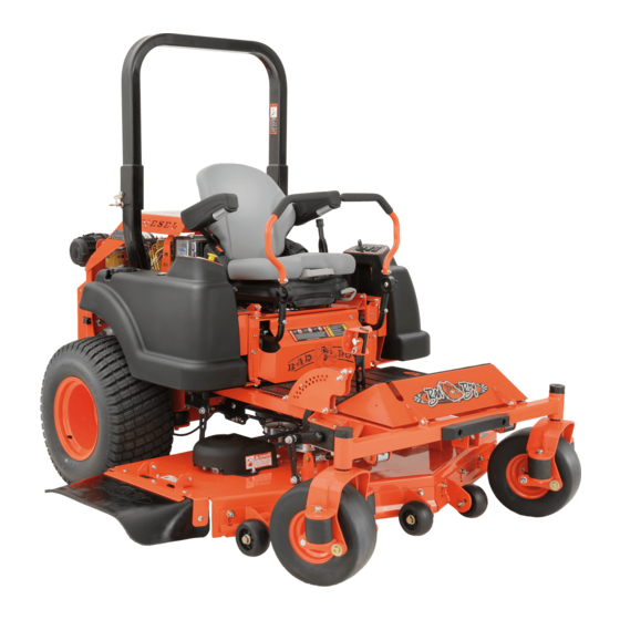
Diesel 1500cc zero-turn mower
Hide thumbs
Also See for Diesel 7200:
- Owner's, service & parts manual (56 pages) ,
- Owner's, service & parts manual (52 pages)

Related Manuals for Bad Boy Diesel 7200


Summary of Contents for Bad Boy Diesel 7200
- Page 1 DIESEL 1500 MODEL ZERO-TURN MOWER OWNER’S, SERVICE & PARTS MANUAL For additional information, please see us at www.badboymowers.com Bad Boy, Inc. 102 Industrial Drive Batesville, Arkansas 72501 ©2015 12-11...
-
Page 2: Table Of Contents
TABLE OF CONTENTS Basic Information ....................Section 1 (page 4) Bad Boy Safety Guidelines ................Section 2 (pages 5–8) Operation ......................Section 3 (pages 9) Maintenance ...................... Section 4 (page 10) Storage and Transportation ................Section 5 (page 12) Troubleshooting and FAQ ..................Section 6 (page 13) Controls ...................... - Page 3 This manual applies to the following equipment: Bad Boy Diesel Series Diesel 7200 72˝ 1500cc 4-Cylinder Diesel Diesel 6100 61˝ 1500cc 4-Cylinder Diesel COMMONLY USED ITEMS AND PART NUMBERS Gator Blade 72" Hi-Lift Fusion Wave Blade 038-5400-00 Blade 038-7230-00 038-7215-00 Gator Blade 61"...
- Page 4 Congratulations on the purchase of your new Bad Boy Mower! The purpose of this manual is to assist operators in maintaining and operating their machine. The information and instructions in this manual can help you attain years of performance from your new Bad Boy. Also, check out our website to learn more about the Bad Boy family.
-
Page 5: General Operation
SECTION 2: MOWER SAFETY GUIDELINES Never allow untrained people to operate this machine. It is the owner’s responsibility to get training and see to it that anyone who has permission to use your machine receives the proper training. Do not mow around people. The factory discharge chute is designed to deflect debris downward, but it could be possible for debris to be thrown in a way that can cause damage to people or property. -
Page 6: Slope Operation
SLOPE OPERATION Slopes are a major factor related to loss of control and tip over accidents, which can result in severe injury or death. Operation on all slopes requires extra caution. If you cannot back up the slope, or you feel uneasy on it, do not mow it. 2.22 Mow up and down slopes, not across. - Page 7 SERVICE: SAFE HANDLING OF DIESEL To avoid personal injury or property damage, use extreme care in handling diesel. 2.45 Extinguish all cigarettes, cigars, pipes, and all other sources of ignition. 2.46 Use only an approved diesel container. 2.47 Never remove fuel cap or add fuel with the engine running. 2.48 Allow engine to cool before refueling.
-
Page 8: Safety Interlock System
SAFETY INTERLOCK SYSTEM Your Bad Boy mower is equipped with a safety interlock system. This system is designed to prevent serious injury or death to the operator and other people or property damage. The system consists of an operator presence switch in the seat, the parking brake, drive lever neutral position, the mower blade engagement switch, and the ignition switch. - Page 9 The machine could lose traction on a decline or tip backwards on an incline. 3.14 Once you become comfortable with your Bad Boy Mower you will notice your overall mowing time will decrease.
- Page 10 SECTION 4: MOWER MAINTENANCE Interval Every 50 First Every 100 Every Every Daily hours or hours or Section Maintenance annually* hours annually* hours hours Check and add engine oil ● Section 3 Section2 Check all belts for proper ● (Pump) 6 alignment (Deck) Check tire pressure and wheel...
- Page 11 Maintenance Log Date: Hours: Performed: Performed Date: Hours: Date: Hours: Performed: Performed Date: Hours: Performed Date: Hours: Date: Hours: Performed: Performed Date: Hours: Date: Hours: Performed: Performed Date: Hours: Performed Date: Hours: Performed: Date: Hours: Date: Hours: Performed: Performed Date: Hours: Performed Date:...
- Page 12 SECTION 5: MOWER STORAGE & TRANSPORTATION Keep machine from collecting debris by storing in a covered area while not in use. 5.2 Fuel can harm your machine if left for more than 30 days without changing. 5.3 Disconnect the negative battery cable when machine will be stored for more than 30 days. 5.4 Always secure machine properly when transporting machine.
- Page 13 SECTION 6: TROUBLESHOOTING Q: How do I prevent an uneven cutting pattern and increase the quality of cut? A: Check tire pressure, check blade sharpness (replace blades or sharpen at least once per year or when needed), make sure blades are tightened properly, check spring and belt tension, check the underside of the deck to ensure the mower deck is free of grass build-up and debris, make sure your machine is at full throttle, and vary your mowing pattern each time you cut your grass.
- Page 14 SECTION 7: CONTROLS Ignition Switch—Bad Boy mowers have a three position ignition switch: off, run, and start. With key inserted, rotate it clockwise to START position and release key when engine starts. Switch will automatically return to he RUN position.
- Page 15 Before moving the mower, turn the bypass valves counterclockwise one-half to one revolution. The valve stems on each pump are located near the top and are identified as a hex stud. 8.4 Your Bad Boy Mower Weighs: DIESEL SERIES: 1607—1935 lbs *** Weights fluctuate with the addition of accessories.
-
Page 16: Greasing Bearings
SECTION 10: MOWER BLADE MAINTENANCE 10.1 Check mower blades after each use. This is essential for maintaining well-groomed turf. Keep the blades sharp. If a dull blade is used for cutting, the grass will tear rather than cut. This could damage the grass leaving a brown frayed top on the grass within a few hours. A dull blade will also require more power from the engine. -
Page 17: How To Choose The Right Blade
HOW TO CHOOSE THE RIGHT BLADE Essentially there are only TWO basic styles of mowing blades used or approved for use on our current products: 1) The standard style of mowing blade is essentially designed for cutting grass and effectively discharging the clippings out from the deck to fall onto the lawn or to be captured in a grass collection system. -
Page 18: Mowing Tips
MOWING TIPS: • Mow header strips at the ends of the lawn and around flower beds first. Make them wide enough that you can turn the mower around in the already mown section. Then mow back and forth between these header strips overlapping each lap by about 1/8 the width of the mower’s deck. -
Page 19: Service Section
50 hours of use; then at intervals of 250 usage hours. Use only Bad Boy replacement filters. Use of any other filters may result in damage to the hydraulic system and void the warranty. - Page 20 Purging Procedure Due to the effects air has on the efficiency in hydrostatic drive applications, it is critical that the air is purged from the system. These purge procedures should be implemented any time a hydrostatic system has been opened to facilitate maintenance or any additional oil has been added to the system.
- Page 21 Engine. To access the engine remove the knob on top of the engine cover plate. The oil drain plug is located on the bottom of the engine. Bad Boy recommends that the oil and filter be changed at intervals of 250 usage hours or yearly, whichever occurs first.
- Page 22 3.1 Changing your engine oil and oil filter 1) After the engine has been run at the normal operating temperature, stop the engine. 2) Remove the oil drain plug located underneath the engine. Allow the oil to drain into a drain pan.
- Page 23 When servicing the fuel system on the CAT Diesel, it is necessary to purge the air from the system by loosening the 9/16˝ bolt on top of the fuel filter and pumping the fuel bulb (located underneath the radiator) until air bubbles are no longer visible.
- Page 24 Remove and inspect air cleaner weekly. (More often in dusty conditions). Do not blow filter out with air pressure, this will cause the filter to be filled with tiny holes that will allow dirt to enter. Instead, tap filter on side to remove any debris. Replace at least once a year, more often in dusty conditions.
- Page 25 SECTION 4: ELECTRICAL SYSTEM The fuses on the 1500cc Diesel are located behind the left swing away tank. The top 40 amp fuse is the main fuse and the two 15 amp fuses are for the linear actuator and for the clutch. Always check the condition of the wiring harness ground cable.
- Page 26 PAGE 26...
- Page 27 SECTION 5: FRAME The front fork nuts require a torque of 40ft-lbs. First remove the dust cap. While applying this torque, turn the fork itself to ensure no damage is done to the bearing. This operation is only necessary if a repair requires it. Torque rear wheel lugs to 65-75 ft.
- Page 28 The pump belt tensioner is located under the engine and has a grease fitting at its pivot point. Grease at every engine oil change. The deck belt tensioner is located at the rear of the deck and has a grease fitting on its pivot point. Grease at every engine oil change.
- Page 29 SECTION 6: CUTTING DECK Deck belt removal 1) Remove ignition key. 2) Raise the deck to its highest position. 3) Remove the right pulley cover. 4) While lifting up on the belt (as shown in the photograph), rotate the pulley until the belt is free of the pulley.
- Page 30 Leveling the Deck 1) Start on a flat level surface and set the air pressure in all four tires to 12 psi. 2) Get two 2x4s and make sure that the wider sides are similar length. 3) Take off the foot pedal and raise the floor plate.
- Page 31 The deck spring tension is critical. If the tension is too high, premature failure of the deck belt and blade spindles can occur. If the tension is too low, the belt can ‘jump off’ or slip on the pulleys. This results in reduced cut quality and early belt failure.
- Page 32 Blade Removal: To change blades, it may be easier to use a piece of wood to keep the blade from turning so that the bolt can be loosened. Use a 15/16” socket and impact Drill, or a wrench and an extension to gain more leverage. You might need to put a ¾”...
-
Page 33: Parts Section
PARTS SECTION Diesel CAT Suspension Fork Assembly Suspension Fork Assembly ITEM PART NUMBER DESCRIPTION 023-0020-00 Suspension Fork Top/Side Combo 023-0012-00 Suspension Fork - Bottom Left 023-0013-00 Suspension Fork - Bottom Right 037-0010-00 Front Suspension Fork Spindle 013-5300-00 1/2" Flange Nut 018-2030-00 1/2"... - Page 34 1500cc Diesel Drive Arms Welded to Frame PAGE 34...
- Page 35 Parts List ITEM PART NUMBER DESCRIPTION 034-8025-00 Drive Lever Spring 032-5055-00 Bushing for 2012 Drive Arms 019-8027-00 .515 ID Nylon Shoulder Washer 024-6034-00 1/4" Press in Grease Fitting 013-8050-00 1/2-13 Nylon Flange Nut 013-8043-00 5/16" Nut 018-8063-00 5/16" x 3/4" Hex Bolt 013-6051-00 3/8"...
- Page 36 Diesel Tanks PAGE 36...
- Page 37 Diesel Tanks Assembly ITEM PART NUMBER DESCRIPTION 067-3000-00 Left Fuel Tank with Fender 083-4014-00 Hour Meter 079-3402-00 Control Panel (Left) 018-1040-00 Light Plug 077-8076-00 Ignition Switch 042-9000-00 Ignition Key 031-2010-00 Left Tank Support 031-2011-00 Right Tank Support 018-2015-00 10-32 x 1 Button Head Bolt 080-7000-00 Diesel Seat Frame 018-8065-00...
- Page 38 Diesel Frame PAGE 38...
- Page 39 Diesel Frame, Actuator, Floor Board, and Height Indicator ITEM PART NUMBER DESCRIPTION 070-5550-00 Diesel 4cyl 72" Frame 028-7920-00 Actuator Bar 031-7000-00 Height Indicator Lever 013-9002-00 5/16" Flange Nut 019-6042-00 .360 ID Plastic Washer 028-5203-00 Height Indicator Bar 018-2007-00 5/16" x 1" Bolt 039-2008-00 Deck Stop Bracket 2008 Actuator...
- Page 40 1500cc Diesel Seat Frame DETAIL A DETAIL B DETAIL C PAGE 40...
- Page 41 Diesel Seat Frame ITEM PART NUMBER DESCRIPTION 069-8054-00 Hand Brake Assembly 062-8013-00 Filter Head 063-8014-00 Hydraulic filter 024-5050-00 Filter Head Fitting 018-8051-00 1/4-20 X 9 Carriage Bolt 077-8073-00 Switch 018-8059-00 5/16" x 1 3/4" Hex Bolt 013-8051-00 1/4" Wing Nut 080-7000-00 2007 Diesel Seat Frame 068-8050-00...
- Page 42 Diesel Pump Plate Assembly DETAIL B 72" Deck only DETAIL C DETAIL A PAGE 42...
- Page 43 Diesel Pump Plate Assembly ITEM PART NUMBER DESCRIPTION 026-8030-00 Pump Plate Diesel 018-5043-00 3/8" x 1 1/4" Carriage Bolt 024-3050-00 1/4" Drive in Grease Fitting 033-6001-00 4 3/4" Idler Pulley 039-5950-00 Pump Idler Bracket only for 61" Deck 013-8050-00 1/2-13 Nylon Flange Nut-Orange 018-7016-00 1/2"...
- Page 44 1500cc Diesel Back Pump Cover PAGE 44...
- Page 45 1500cc Diesel Suspension DETAIL A PAGE 45...
- Page 46 Diesel Suspension & Back Pump Cover Assemblies ITEM PART NUMBER DESCRIPTION 014-5920-00 Diesel Back Pump Cover 2008 Bottom 039-0070-00 Back Cover Hinge Bracket 014-5921-00 Diesel Back Pump Cover 2008 Top 059-8010-00 Diesel Hood 4 Cyl 018-8065-00 5/16" x 1" Carriage Bolt 019-6042-00 .360 ID Plastic Washer 018-8064-00...
- Page 47 Radiator Assembly Diesel Hydraulic Cooler PAGE 47...
- Page 48 Radiator Assembly ITEM PART NUMBER DESCRIPTION 061-5000-00 Radiator- Diesel 094-5088-00 Radiator Screen-Diesel 072-8090-00 Diesel Clamp 1 3/4" Vinyl 051-3000-00 Top Radiator Hose for Diesel 051-3001-00 Bottom Radiator Hose for Diesel 072-2003-00 1 1/8" Hose Clamp 013-8049-00 5/16" Nylon Flange Nut 018-2007-00 5/16"...
- Page 49 Diesel Air filter Assembly Diesel Air Filter Assembly ITEM PART NUMBER DESCRIPTION 088-1018-00 Canister for All Diesel Models 088-1017-00 Enginaire Air canister cap 088-1019-00 Mounting Bracket For Diesel Air Filter 063-2050-00 Diesel Air Filter- Outer 063-2060-00 Diesel Air Filter- Inner 088-1020-00 Debris Plug-Enginaire Filter 013-8043-00...
- Page 50 1500cc CAT Diesel Engine PAGE 50...
- Page 51 35HP Diesel Engine ITEM PART NUMBER DESCRIPTION 015-5600-00 1500cc CAT Diesel Engine 039-1010-00 Diesel Throttle Bracket (4 Tier) 017-3000-00 Stub Shaft 019-4008-00 1/4" Lock Washer 201-8005-00 Air Cleaner Support Diesel 018-2001-00 M8 x 1.25 x 25mm Hex Head Bolt 018-5320-00 M8 x 1.25 x 30mm Hex Head Bolt 019-8051-00 5/16"...
- Page 52 Diesel 61" Deck DETAIL A DETAIL B DETAIL D DETAIL C PAGE 52...
- Page 53 Diesel 61" Deck ITEM PART NUMBER DESCRIPTION 060-6130-00 61" AOS Deck 033-5000-00 5 3/4" Deck Idler Pulley 033-6004-00 6 1/4" Drive Pulley 034-2020-00 2015 Deck Idler Spring Outlaws 039-4863-00 60" Discharge Lower Bracket 039-6945-00 Deck Idler 018-2018-00 1/2 x 3 1/2 Flange Bolt Grade 8 025-5338-00 .502 ID X .750 OD X 1.500 Long Spacer 013-8050-00...
- Page 54 Diesel 72" Deck DETAIL B DETAIL C DETAIL A DETAIL D PAGE 54...
- Page 55 Diesel 72" Deck ITEM PART NUMBER DESCRIPTION 060-7201-00 72" ( Deck Only) 037-4000-50 Double Bearing Spindle 019-4807-00 5/8" Lock Washer 018-6020-00 5/8" x 1 1/2" Grade 8 Hex Bolt (Fine) 018-6019-00 1/2"-20 x 1 1/2 - Grade 5 Fine Thread Bolt 019-6020-00 1/2 Belleville Washer 038-7230-00...
- Page 56 037-4000-50 Double Bearing Spindle Parts List ITEM PART NUMBER DESCRIPTION 037-4001-00 4000 Series Spindle Housing 037-4002-00 4000 Series Spindle Spacer 037-9050-00 Locking Collar w/ 1/4"-20 Set Screw 037-8002-00 Spindle Dust Cap 037-6026-00 ZT-AOS Spindle Shaft 037-6023-00 Bearing - 6206 PAGE 56...
- Page 57 Right 091-1104-00 091-2063-00 Throttle Preheat Decal 091-3017-00 091-3300-00 Pump Belt Route Decal Caution Decal – Front Grill 091-2001-00 Bad Boy Oval Logo Decal 091-0919-00 ArmorTek Decal 091-8000-00 091-2050-00 091-3060-00 EZ Ride Patent Decal Low Sulfur Decal Swing-Away Patent Decal 091-0918-00...
-
Page 58: Limited Warranty
The leading edge of the deck shell will be warranted for the entire lifetime of the machine to the original purchaser against defects in materials and workmanship. Labor required to repair or replace the leading edge of the deck shell will be covered by Bad Boy Inc. for two years and at the unit owner’s expense during the balance of the lifetime of the machine. - Page 59 Bad Boy, Inc. 102 Industrial Drive Batesville, AR 72501 www.badboymowers.com Technical Support: ............techsupport@badboymowers.com Warranty: ..................warranty@badboymowers.com Parts: ....................partsdept@badboymowers.com WARRANTY REGISTRATION Ensure selling dealership has registered mower within 30 days of purchase to validate warranty. Please record your serial number, date of purchase and dealership information for your records.
- Page 60 For additional information, please see us at www.badboymowers.com Bad Boy, Inc. 102 Industrial Drive Batesville, Arkansas 72501...
Need help?
Do you have a question about the Diesel 7200 and is the answer not in the manual?
Questions and answers