Table of Contents

Subscribe to Our Youtube Channel
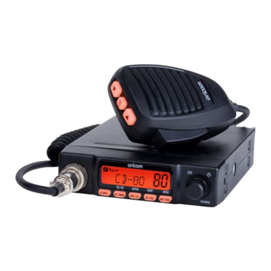
Related Manuals for Oricom UHF180F


Summary of Contents for Oricom UHF180F
-
Page 1: Operating Instructions
Operating Instructions UHF180F 80 Channel UHF CB Radio Keep this user guide for future reference. Always retain your proof of purchase in case of warranty service and register your product on line at: AUSTRALIA: www.oricom.com.au... - Page 2 Need Help? If you need assistance setting up or using your Oricom product now or in the future, call Oricom Support. Australia 1300 889 785 or (02) 4574 8888 www.oricom.com.au Mon-Fri 8am – 6pm AEST New Zealand 0800 67 42 66 www.oricom.co.nz...
-
Page 3: Table Of Contents
During this time wideband channel use will be gradually phased out as users upgrade their existing radio’s. This means that the new Oricom narrowband radio you have purchased will have more channels than older wideband radios. Some of these channels are locked and cannot be used, (see the attached channel chart for more information). -
Page 4: Safety Information And Warnings
Safety Information and Warnings Please read before installing or operating Your Oricom Radio The operation of your UHF radio in Australia and New Zealand is subject to conditions in the following licenses: In Australia the ACMA Radio communications (Citizen Band Radio Stations) and in New Zealand by MED the General User Radio License for Citizen Band Radio. -
Page 5: Controls And Connectors
Controls and Connectors Box Contents UHF180F 1 x RF Radio 1 x Microphone Hanger 1 x Standard Microphone 1 x User Guide 1 x DC Power Cord with inline fuse 1 x Mounting bracket with mounting screws for RF Radio... -
Page 6: Front View
Controls and Connectors Front View 1. Microphone connector 6. Priority Channel On/Off, Key Lock On/Off, Alpha-numeric display I3 2. LCD Display 7. ID setting, 5 tone SelCall, Quiet, I4 3. Power On/Off, channel & Volume control 8. Monitor, TSQ On/Off, Menu, I5 4. -
Page 7: Rear View
Controls and Connectors Rear View Rear view of Radio 1. 3.5mm external jack for optional 8 ohm speaker 2. Power Supply connection 3. Antenna connection Standard Microphone 1. Push To Talk (PTT) button 2. Volume Up, Channel Up 3. Volume Down, Channel Down 4. - Page 8 Controls and Connectors LCD Icons & Indicators 10. Open Scan 1. FUNCTION 2. RX or TX Signal strength 11. Priority Scan 3. Transmitter Indicator 12. Selelctive call Sending "To" 4. Receiver Indicator 13. Selective call Receiving "From" 5. Quiet mode 14.
-
Page 9: Installation
Installation INSTALLATION CAUTION When installing your radio in your vehicle, check that during installation you do not damage any wiring or vehicle components that may be hidden around the mounting position. For optimum performance your radio needs to be installed correctly. If you are unsure about how to install your radio, we suggest you have your radio professionally installed by a UHF specialist or Auto electrician. - Page 10 Installation 1. Fix the mounting bracket in place by screwing through the slots in the bracket. 2. Connect the standard microphone to the socket, and tighten up the thumb screw. Rubber washer should be placed between the bracket and radio .
-
Page 11: Over Voltage Protection
Installation DC Power Connection The Radio is designed for 13.8 Volt DC, negative earth installations only (i.e. where the negative battery terminal connects to the chassis of the vehicle). For installation on 24 volt systems an inverter (not supplied) will need to be used. -
Page 12: Antenna Information
Optional accessories If required you may install an external (8 ohm, max 5w power) speaker fitted with a 3.5mm plug (not supplied). There is a jack located on the rear of the radio and on the UHF180F. -
Page 13: Operations
200RX UHF180F Volume control * The UHF180F has a rotary electric volume control. Adjust the volume by rotating the channel knob clock-wise or adjust the volume control by pressing the Volume Up or Volume Down buttons on the microphone. 200RX Channel Selection * Briefly press the PWR button. -
Page 14: Multi Function Buttons
Operations Multi Function buttons To use the primary function (F, SC, PRI, ID, MO), press the required button. To use the secondary function (DPX, MEM, LO, CAL, TSQ), press and hold the button for 2 seconds. To use the third function (OS/GS, ALPHA, QUIET, MENU), press F/DPX and press the required button. -
Page 15: Priority Channel
Operations Priority Channel To store a Priority Channel, press the PRI/LO button. The letter "P" will appear when the priority channel is set. The channel you selected as your Priority Channel will then be automatically monitored during the Group Scan. Note: You can only store one channel as your priority channel. - Page 16 Operations Selecting the Required CTCSS Tone To pre-select the CTCSS tone on your radio, please refer to the MENU settings on page 24. Enabling CTCSS on a Channel CTCSS when enabled is on all channels excluding channels 5 and 35. 1.
-
Page 17: Priority Scan
Operations Open Scan Priority Scan With Scan the Radio scans for activity, but in addition, it also inserts your Priority Channel into the scan sequence. This means that your Priority Channel will be monitored regularly while scanning to ensure that no calls are missed. Any signals received on your Priority Channel will take precedence over any signals received on the other channels. - Page 18 1. Press the ID/CAL button to select the CALL TO mode. 2. To select the required Identity in memory locations 'C0' to 'C9'. Rotate the channel knob on the front display of the UHF180F. 3. When the required Selcall Memory is displayed, press and hold the ID/CAL button to send TO.
- Page 19 Operations Displaying ALPHA Names To display the Selcall’s ALPHA Name You must have the radio’s ALPHA display mode selected. To select the ALPHA display mode briefly press the F/DPX button followed by the ALPHA button. ‘ALPHA’ or ‘NUMER’ will be displayed for 2 seconds below the channel display to indicate the selected mode.
-
Page 20: Receiving Selcalls
Operations To exit CAL-TO mode Briefly press the ID/CAL button. The radio will return to normal operation. Receiving Selcalls When the Radio receives an ID code that matches your Selcall ID, it will automatically transmit an alarm tone. The caller’s Selcall ID name or number will be displayed. - Page 21 Operations To call the group, program the Base radio Group ID code to 1234A. When you call the group, all of the above vehicles will receive the Group Calling Tone. Group call IDs can be stored in memory the same way as a Standard Selcall ID code, please refer to Entering, Editing and Storing a Selcall ID number at page 10 Radios 100 Radios...
- Page 22 Operations Setting up QUIET Mode To setup QUIET mode you must first ‘tag’ the channels that you want to stay quiet, then activate the QUIET mode. Once QUIET mode is activated, the channels you have tagged will remain quiet to all incoming signals unless your Selcall Ident is received.
- Page 23 Operations Third functions MENU list * Use the channel knob to change the value of each setting. * Use the Scan button to select the next function. * If a button is not pressed within 8 seconds the Radio will automatically exit the menu mode.
- Page 24 Operations SQL: The radio has 8 preset ( off - 7) squelch levels: off - SQ off (monitor on condition) 1 - Max sensitivity (min squelch) 7 - min sensitivity (max/tight squelch) CTCSS and DCS setting This feature allows you to receive signals only from callers who have selected the same CTCSS and DCS code.
- Page 25 Operations Auto power off This feature allows the radio to be connected directly to the battery of a vehicle and when enabled will automatically turn the radio off, if it has not been used for a preset period of time 1, 2 or 4 hours. The main purpose of this feature is if the radio is inadvertently left on when directly connected to the battery it automatically turns the radio off to prevent the battery from being discharged.
-
Page 26: Duplex Operation
Operations Duplex Operation General Your radio has a Repeater Access function to allow use of local Repeater stations (if available in your area). Repeaters are shared radio system installed by interested parties (clubs, local business etc.) that pick transmissions on specific channels and re-transmit (or repeat) the received signal to another channel. -
Page 27: Key Lock
If you transmit on CH01 duplex mode, you are actually transmitting on CH31 the repeater station down converts your signal and retransmits on CH01. Your UHF180F allows you to pre-select Duplex operation individually on each channel. Push and hold the F/DPX button for 2 seconds, "DPXON" should appear on the LCD. - Page 28 Operations Turn power on. Briefly press the F/DPX button and then the Power button to access frequency band range. * Display will show default frequency band range. Briefly press the power button, the frequency number should be blinking. * you may use the rotary channel switch to select which channel you want. (example;) * Press and hold the PRI/LO button for 2 seconds, "400"...
-
Page 29: Factory Reset
Operations * press the PRI/LO button, next 2 digits will be blinking for the next frequency digits. * Rotary channel switch to select which 2 frequency digits you want. To store the required frequency, briefly press the ID/CAL button. Briefly press the F/DPX button and Power button to exit. Automatic programming 1. -
Page 30: Uhf Channels And Frequencies
UHF channels and frequencies Channel Frequency Table Radiocommunications (Citizen Band Radio Stations) Class Licence 2002 No licence is required to own or operate this radio in Australia and New Zealand. The Radiocommunications (Citizen Band Radio Stations) Class Licence 2002 contains the technical parameters, operating requirements, conditions of licence and relevant standards for Citizen Band (CB) radios. - Page 31 476.6125 477.1125 477.1125 476.6250 476.6250 477.1250 477.1250 476.6375 476.6375 477.1375 477.1375 UHF channels and frequencies 476.6500 476.6500 477.1500 477.1500 476.6625 476.6625 477.1625 477.1625 476.6750 476.6750 477.1750 477.1750 476.6875 476.6875 477.1875 476.7000 476.7000 477.2000 477.2000 476.7125 476.7125 477.2125 476.7250 476.7250 477.2250 477.2250 476.7375 476.7375...
- Page 32 UHF channels and frequencies 38 CTCSS CODE LIST CODE Frequency(Hz) CODE Frequency(Hz) 131.8 67.0 136.5 71.9 141.3 74.4 146.2 77.0 151.4 79.7 156.7 82.5 162.2 85.4 167.9 88.5 173.8 91.5 179.9 94.8 186.2 97.4 192.8 100.0 203.5 103.5 210.7 107.2 218.1 110.9 225.7...
-
Page 33: Uhf180F Technical Specification
UHF180F Technical Specification UHF180F Technical Specification Compliance AS/NZS 4365:2011 Frequency Range TX 476.425 - 477.4125 MHz Frequency Range RX 400 - 512MHz Number of TX/RX Channels 75 UHF CB Number of user programmable RX only Channels Channel Spacing TX/RX 12.5KHz... - Page 34 UHF180F Technical Specification Intermodulation Immunity > 70dB Spurious Immunity > 70dB Audio Output Power 3 Watts Maximum RX Audio de-emphasis -6dB/octave 300Hz to 3kHz Audio frequency response 300Hz to 3kHz External speaker jacks Optional 8 Ohm mono speaker (3.5mm jack.)
-
Page 35: Customer Support
If you have any problems setting up or using this product you will find useful tips and information in the Troubleshooting section of this user guide as well as “Frequently Asked Questions” on our website www.oricom.com.au. If you have further questions about using the product after reviewing the resources above or would like to purchase replacement parts or accessories please call our Customer Support Team. -
Page 36: Express Warranty
Express Warranty Express Warranty (Australia) This Express Warranty is provided by Oricom International Pty Ltd ABN 46 086 116 369, Unit 1, 4 Sovereign Place, South Windsor NSW 2756, herein after referred to as “Oricom”. Oricom products come with guarantees that cannot be excluded under the Australian Consumer Law. - Page 37 Oricom. Oricom will not be liable under this Express Warranty, and to the extent permitted by law will not be liable for any defect, loss, damage or injury arising out of or in connection with a: 1.
- Page 38 Please note that if a Customer Support Team member advises that your product does not qualify for return, this warranty does not apply to your product. Products that are authorised to be returned to Oricom in Australia must include all of the following: • A completed Return Authorisation form •...
-
Page 39: Important Information
Express Warranty Important Information Repair Notice Please be aware that the repair of your goods may result in the loss of any usergenerated data (such as stored telephone numbers, text messages and contact information). Please ensure that you have made a copy of any data saved on your goods before sending for repair. - Page 40 Contact details for Oricom Support and Express Warranty Claims in Australia Oricom International Pty Ltd Locked Bag 658 South Windsor, NSW 2756 Australia Email: support@oricom.com.au Phone: 1300 889 785 or (02) 4574 8888 (Monday to Friday 8am to 6pm AEST) Web: www.oricom.com.au...
Need help?
Do you have a question about the UHF180F and is the answer not in the manual?
Questions and answers