Sony RDR-VX511 Service Manual
Hide thumbs
Also See for RDR-VX511:
- Operating instructions manual (124 pages) ,
- Quick start manual (2 pages)
Table of Contents
Advertisement
QQ
3 7 63 1515 0
SERVICE MANUAL
TE
L 13942296513
System
[
DVD recorder section]
Laser
Semiconductor laser
Audio recording format
Dolby Digital
Video recording format
MPEG Video
[
]
VCR section
Format
VHS NTSC standard
Video recording system
Ro
tary head helical scanning
FM system
Video heads
Double azimuth four heads
Video signal
NTSC color, EIA standards
Tape speed
SP: 33.35 mm/s (1
7
EP: 11.12 mm/s (
11
LP: 16.67 mm/s (
playback only
www
.
http://www.xiaoyu163.com
RDR-VX511/VX515
Maximum recording/playback time
8 hrs. in EP mode (with T-160 tape)
Rewind time
Approx. 1 min (with T-120 tape)
[
Tuner section
Channel coverage
VHF 2 to 13
UHF 14 to 69
CATV A-8 to A-1, A to W, W+1 to
W+84
Antenna
75-ohm antenna terminal for VHF/UHF
[
Timer section
Clock
Quartz locked
Timer indication
12-hour cycle
Timer setting
12 programs in total (max.)
3
/
inches/s)
8
/
inches/s)
16
/
inches/s),
16
x
ao
y
i
http://www.xiaoyu163.com
8
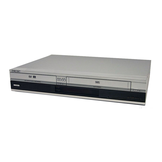
Photo: RDR-VX515
Refer to the SERVICE MANUAL of VHS MECHANI-
CAL ADJUSTMENT MANUAL VII for MECHANICAL
ADJUSTMENTS. (9-921-790-11)
SPECIFICATIONS
Q Q
3
6 7
1 3
]
]
VIDEO CASSETTE RECORDER/
u163
.
2 9
9 4
2 8
RMT-D224A
RDR-VX511/VX515
Canadian Model
TS-10 MECHANISM
1 5
0 5
8
2 9
9 4
Inputs and outputs
LINE 1 IN and LINE 2 IN
VIDEO IN, phono jack (1 each)
Input signal: 1 Vp-p, 75 ohms,
unbalanced, sync negative
AUDIO IN, phono jacks (2 each)
Input level: 327 mVrms
Input impedance: more than 47 kilohms
LINE 2 IN
S VIDEO, 4-pin, mini-DIN jack
Y: 1.0 Vp-p, unbalanced, sync negative
C: 0.286 Vp-p, load impedance 75 ohms
DV IN, 4-pin jack, i.LINK S100
LINE OUT
VIDEO OUT, phono jack (1)
Output signal: 1 Vp-p, 75 ohms,
unbalanced, sync negative
AUDIO OUT, phono jacks (2)
Standard output: 327 mVrms
Load impedance: 47 kilohms
Output impedance: less than 10 kilohms
— Continued on next page —
m
DVD RECORDER
co
9 9
US Model
RDR-VX515
2 8
9 9
Advertisement
Table of Contents

Related Manuals for Sony RDR-VX511


Summary of Contents for Sony RDR-VX511
- Page 1 RDR-VX511/VX515 3 7 63 1515 0 RMT-D224A SERVICE MANUAL US Model RDR-VX511/VX515 Canadian Model RDR-VX515 TS-10 MECHANISM Photo: RDR-VX515 Refer to the SERVICE MANUAL of VHS MECHANI- CAL ADJUSTMENT MANUAL VII for MECHANICAL ADJUSTMENTS. (9-921-790-11) SPECIFICATIONS L 13942296513 Inputs and outputs...
- Page 2 http://www.xiaoyu163.com 3 7 63 1515 0 DIGITA L AUDIO OUT General Dimensions including projecting parts OPTICAL, Optical output jack and controls (w/h/d) Power requirements Approx. 430 × 85 × 334 mm −18 dBm (wave length: 660 nm) 120 V AC, 60 Hz (Approx.
- Page 3 SONY PARTS WHOSE PART NUMBERS APPEAR AS DE FONCTIONNEMENT. NE REMPLACER CES COM- SHOWN IN THIS MANUAL OR IN SUPPLEMENTS POSANTS QUE PAR DES PIÈCES SONY DONT LES PUBLISHED BY SONY. NUMÉROS SONT DONNÉS DANS CE MANUEL OU DANS LES SUPPLÉMENTS PUBLIÉS PAR SONY.
-
Page 4: Table Of Contents
http://www.xiaoyu163.com TABLE OF CONTENTS 3 7 63 1515 0 Precautions Block Diagram ............3-1 Safety Precautions ······························································ 5 PCB Diagrams Servicing Precautions ························································ 7 ESD Precautions ································································· 8 VCR Main PCB ······························································· 4-3 Handling the Optical Pick-up ············································· 9 DVD Main PCB ······························································ 4-7 Reset operation after IC203 or IC205 was replaced ..10 Jack PCB ·······································································... -
Page 5: Safety Precautions
http://www.xiaoyu163.com 3 7 63 1515 0 PRECAUTIONS 1 SAFETY PRECAUTIONS 1) Before returning an instrument to the customer, always make a (4) Insulation Resistance Test Cold Check-(1) Unplug the power safety check of the entire instrument, including, but not limited supply cord and connect a jumper wire between the two prongs to, the following items: of the plug. - Page 6 http://www.xiaoyu163.com 3 7 63 1515 0 6) Product Safety Notice-Some electrical and mechanical parts have special safety-related characteristics which are often not evident from visual inspection, nor can the protection they give necessarily be obtained by replacing them with components rated for higher voltage, wattage, etc.
-
Page 7: Servicing Precautions
http://www.xiaoyu163.com 3 7 63 1515 0 2 SERVICING PRECAUTIONS CAUTION: Before servicing units covered by this service manual 2-2 Insulation Checking Procedure and its supplements, read and follow the Safety Precautions section of this manual. Disconnect the attachment plug from the AC outlet and turn the power ON. -
Page 8: Esd Precautions
http://www.xiaoyu163.com 3 7 63 1515 0 3 ESD PRECAUTIONS Electrostatically Sensitive Devices (ESD) Some semiconductor (solid state) devices can be damaged easily by static electricity. Such components commonly are called Electrostatically Sensitive Devices (ESD). Examples of typical ESD devices are integrated circuits and some field-effect transistors and semiconductor chip components. -
Page 9: Handling The Optical Pick-Up
http://www.xiaoyu163.com 3 7 63 1515 0 4 HANDLING THE OPTICAL PICK-UP The laser diode in the optical pick up may suffer electrostatic breakdown because of potential static electricity from clothing and your body. The following method is recommended. (1) Place a conductive sheet on the work bench (The black sheet used for wrapping repair parts.) (2) Place the set on the conductive sheet so that the chassis is grounded to the sheet. -
Page 10: Reset Operation After Ic203 Or Ic205 Was Replaced
http://www.xiaoyu163.com 3 7 63 1515 0 5 Reset operation after IC203 or IC205 was replaced Be sure to perform the reset by the method described below, if the IC203(IC FLASH MEMORY) or IC205(IC EEPROM) used on the DVD Main board was replaced. Resetting method 1. -
Page 11: General
RDR-VX511/VX515 3 7 63 1515 0 1. GENERAL This section is extracted from RDR-VX515 instruc- tion manual. (2-636-467-11) About this manual What is a Video Cassette Recorder/DVD Recorder? • Instructions in this manual describe the controls on the remote. You can also use the controls on the recorder if... -
Page 12: Hookups And Settings
http://www.xiaoyu163.com 3 7 63 1515 0 Selectable options TOOLS Step 2: Connecting the Selectable options on the System Menu differ Hookups and Settings depending on the media type, disc condition, and The TOOLS menu appears when you press Antenna Cable operating status. - Page 13 http://www.xiaoyu163.com 3 7 63 1515 0 If your TV has component video input jacks Step 3: Connecting to Your TV Connect the COMPONENT VIDEO OUT jacks using a component video cord (not supplied) or three video cords (not supplied) of the same kind and length. You will enjoy accurate color reproduction and Connect the supplied audio/video cord to the LINE OUT (AUDIO L/R/VIDEO) jacks of the recorder.
- Page 14 Akai VOL +/– Notes TV/VIDEO • If the supplied remote interferes your other Sony DVD Centurion recorder or player, change the command mode number Coronado for this recorder (page 24). • Use the batteries correctly to avoid possible leakage...
- Page 15 Audio connected TV appears. DTS signal appears. Dubbing remote to one that differs from the other Sony Features Select the setting that matches your TV Disc Setting DVD recorder or player. Options Easy Setup type.
-
Page 16: Quick Guide To Disc Types
http://www.xiaoyu163.com 3 7 63 1515 0 Connecting to the LINE 1 IN jacks Quick Guide to Disc Types You can connect a second VCR or similar device. Recordable and Playable Discs Other VCR, etc. LINE OUTPUT Audio/video cord LINE 1 IN (not supplied) VIDEO AUDIO... -
Page 17: Dvd Playback
http://www.xiaoyu163.com 3 7 63 1515 0 Discs that cannot be played To stop playback If you try to play any other DVD VIDEO, a message will appear on the TV screen to indicate • CD-Rs/CD-RWs, other than those recorded in Press x STOP. -
Page 18: Searching For A Title
http://www.xiaoyu163.com 3 7 63 1515 0 – you make a recording. Button Operation Disc Playing quickly with sound (Scan Audio) (DVDs with Dolby Digital soundtracks Repeating a specific portion REPEAT Displays the items to be repeated when pressed. Select an item using M/m, and press ENTER. Video only) (Repeat A-B Play) - Page 19 http://www.xiaoyu163.com 3 7 63 1515 0 Press </, to select the bookmark to be Select “Music,” and press ENTER. Note Playing MP3 Audio Tracks erased. The “Music” display appears. Depending on the disc, you may not be able to use the Press CLEAR.
-
Page 20: Dvd Recording
http://www.xiaoyu163.com 3 7 63 1515 0 D Remaining disc space (in stop mode) • Progressive and lossless compression JPEG image files Displaying the Playing Time are not supported. Remaining time of the current title (during • The image size that the recorder can display is limited playback) and Play Information to width 32 - 7680 pixels by height 32 - 8192 pixels. - Page 21 http://www.xiaoyu163.com 3 7 63 1515 0 Press REC MODE repeatedly to select the • You cannot change the channel or input source during recording. DVD Timer Recording recording mode. The display changes on the TV screen as Record Recording using the Quick Timer 0:00:03 follows: Video...
- Page 22 http://www.xiaoyu163.com 3 7 63 1515 0 Press REC MODE repeatedly to select the If the timer settings of a Synchro-Recording Select the timer setting you want to change Changing or Canceling DVD recording mode. and another timer recording overlap or cancel, and press ENTER. The display changes on the TV screen as Regardless of whether or not the program is a The sub-menu appears.
-
Page 23: Dvd Editing
http://www.xiaoyu163.com 3 7 63 1515 0 To edit original titles z Hint You can switch the Title List to show original or Playlist. Editing a Title Edits made to the original titles are final. If you DVD Editing While the Title List menu is turned on, press ORIGINAL/ plan to retain an unaltered original recording, PLAYLIST repeatedly. - Page 24 http://www.xiaoyu163.com 3 7 63 1515 0 Select “Yes,” and press ENTER. Press CHAPTER MARK at the point where you Select the character you want to enter Changing the Name of a want to divide the title into chapters. using M/m/</,, and press ENTER. The display asks whether to use the same title name as before.
- Page 25 http://www.xiaoyu163.com 3 7 63 1515 0 Select “Edit Playlist,” and press ENTER. Press ENTER. “Move”: Allows you to change scene order “Start” is selected. (page 65). The “Playlist” Title List appears. The display asks for confirmation. Modify 10:10 AM “Add”: Allows you to add other scenes before Select “Yes,”...
-
Page 26: Vcr Playback
http://www.xiaoyu163.com 3 7 63 1515 0 To stop playback Adjusting the picture (tracking) Press x STOP. VCR Playback You can manually adjust tracking if the recording To eject the tape quality is too poor to be remedied by the VCR’s Playing Press Z OPEN/CLOSE. -
Page 27: Vcr Recording
http://www.xiaoyu163.com 3 7 63 1515 0 E Channel or input source Notes Displaying the Playing Time Selecting the Sound During F Date and time • To play a tape in stereo, you must use the A/V and Play Information Playback connections. - Page 28 http://www.xiaoyu163.com 3 7 63 1515 0 Press TIMER. When the counter reaches “0:00,” the recorder Notes VCR Timer Recording stops recording and turns off. • The remaining tape length may not be indicated Timer – Standard 10:10 AM accurately for short tapes such as T-20 or T-30, or tapes No Rec To Date Start...
-
Page 29: Dubbing (Tapa Y Dvd)
http://www.xiaoyu163.com 3 7 63 1515 0 Select the timer setting you want to change • You cannot change the timer settings for a recording Notes Changing or Canceling VCR currently underway. or cancel, and press ENTER. • The recorder starts recording only after detecting the •... -
Page 30: Dv/D8 Dubbing (Dv/D8 Y Dvd)
http://www.xiaoyu163.com 3 7 63 1515 0 Insert a source disc. z Hints dubbing. Otherwise the disc’s menu is Dubbing From a DVD to a • A black (no signal) screen at the end of the dubbed disc recorded until the tape reaches its end. Press DVD to operate the DVD recorder. - Page 31 http://www.xiaoyu163.com 3 7 63 1515 0 Connecting a Digital Video DV/D8 Dubbing (DV/D8 t DVD) Camera to the DV IN Jack Disc will be finalized. Do you want to continue ? Before DV/D8 Dubbing Cancel You can connect a digital video camera to the DV IN jack on the recorder to record or edit from a This section explains dubbing with a digital video DV/D8 format tape.
-
Page 32: Settings And Adjustments
http://www.xiaoyu163.com 3 7 63 1515 0 Select “Setup,” and press ENTER. • Noise may occur when you switch the audio sampling z Hint mode (48 kHz/16 bits t 32 kHz/12 bits). You can also perform One Touch Dubbing when you The “Setup”... - Page 33 http://www.xiaoyu163.com 3 7 63 1515 0 automatically search for a channel that carries 16:9 Standard Video Settings (Video) a time signal. Displays a standard picture. Clock Set CH 10:10 AM Cinema 1 White colors become brighter The “Video” setup allows you to adjust items Title List and black colors become richer, related to the image, such as size and color.
- Page 34 Select this to run the Easy Setup program. After step 3 above, select “Parental,” and Change Password Level 8 (Adults) Timer Sony DVD player or more than one Sony DVD press ENTER. Level 7 recorder” on page 24. Edit • If you have not entered a password, the...
-
Page 35: Additional Information
, Check that the safety tab has not been removed. , The recorder cannot play audio tracks in the video heads using a Sony video head cleaning MP3PRO format. cassette. If a Sony cleaning cassette is not Timer recording is not complete or did not start Nothing happens when z REC is pressed. - Page 36 “SONY , Check that the safety tab has not been removed. If a Sony cleaning cassette is not available in your DVD” appears in the front panel display. Clean the cabinet, panel, and controls with a soft area, have the heads cleaned at your nearest Sony , When static electricity, etc., causes the recorder...
- Page 37 http://www.xiaoyu163.com 3 7 63 1515 0 Remote Guide to Parts and Controls For DVD functions Buttons with an orange dot next to them can be For more information, see the pages in parentheses. used with your TV when the TV/DVD·VIDEO switch is set to TV.
- Page 38 http://www.xiaoyu163.com 3 7 63 1515 0 DVD-RW (page 28) Glossary A DVD-RW is a recordable and rewritable disc Front panel display that is the same size as a DVD VIDEO. The DVD- RW has two different modes: VR mode and Video Chapter (page 38) mode.
- Page 39 http://www.xiaoyu163.com 3 7 63 1515 0 “Combine Titles” 63 DVD+R 28 “Manual Set” 94 SYNCHRO REC 51 Index “Command Mode” 25 DVD+R DL 28 MARKER 39 “Synchro Recording” 51 Quick Timer 47 COMPONENT VIDEO OUT DVD+RW 28 MENU 32 DVD-R 28 Menu System Menu 10 Words in quotations appear in...
- Page 40 http://www.xiaoyu163.com 3 7 63 1515 0 MEMO L 13942296513 u163 1-30E http://www.xiaoyu163.com...
-
Page 41: Disassembly And Reassembly
RDR-VX511/VX515 3 7 63 1515 0 2. DISASSEMBLY AND REASSEMBLY 2-1 CABINET AND PCB 2-1-1 Cabinet Top Removal 2-1-3 Ass’y Front Panel Removal 1 REMOVE 1 SCREW 3 Lift up the Cabinet Top in the direction of arrow 1 REMOVE... -
Page 42: Chassis Removal
http://www.xiaoyu163.com 3 7 63 1515 0 2-1-5 Chassis Removal 2 REMOVE 4 SCREWS 3 REMOVE 4 SCREWS 1 REMOVE 2 SCREWS VCR DECK DVD DECK 5 REMOVE 5 SCREWS 6 REMOVE 2 SURPORTER VCR MAIN PCB 4 REMOVE 7 SCREWS DVD MAIN PCB FUNCTION TIMER PCB L 13942296513... -
Page 43: Circuit Board Locations
http://www.xiaoyu163.com 3 7 63 1515 0 2-2 CIRCUIT BOARD LOCATIONS L 13942296513 u163 Fig. 2-7 Circuit Board Locations http://www.xiaoyu163.com... -
Page 44: Vcr Deck Parts Locations
http://www.xiaoyu163.com 3 7 63 1515 0 2-3 VCR DECK PARTS LOCATIONS 2-3-1 Top View L 13942296513 Fig. 2-8 Top parts Location-1 1 GEAR FL CAM 2 MOTOR LOADING ASS’Y 3 LEVER FL ARM ASS’Y 4 HOLDER FL CASSETTE ASS’Y 5 LEVER FL DOOR 6 SLIDER FL DRIVE u163 http://www.xiaoyu163.com... - Page 45 http://www.xiaoyu163.com 3 7 63 1515 0 L 13942296513 qa 0 qs Fig. 2-9 Top Parts Location-2 1 FE HEAD 8 DISK S REEL 2 CYLINDER ASS’Y 9 LEVER S BRAKE ASS’Y 3 ACE HEAD ASS’Y 0 GEAR IDLE 4 LEVER UNIT PINCH ASS’Y qa LEVER IDLE 5 LEVER #9 GUIDE ASS’Y qs LEVER T BRAKE ASS’Y...
-
Page 46: Bottom View
http://www.xiaoyu163.com 3 7 63 1515 0 2-3-2 Bottom View L 13942296513 Fig. 2-10 Bottom Parts Location 1 GEAR JOINT 1 2 GEAR JOINT 2 3 BRAKET GEAR 4 MOTOR CAPSTAN ASS’Y 5 LEVER T LOAD ASS’Y 6 GEAR LOADING DRIVE 7 LEVER S LOAD ASS’Y 8 HOLDER CLUTCH ASS’Y 9 BELT PULLEY... -
Page 47: Vcr Deck
http://www.xiaoyu163.com 3 7 63 1515 0 2-4 VCR DECK 2-4-1 Holder FL Cassette Ass’y Removal 2-4-2 Lever FL Arm Ass’y Removal 1) Pull the Holder FL Cassette Ass’y 1 to the eject position. 1) Push the hole “A” in the direction of arrow “B” use the pin.(about 2) Pull the Holder FL Cassette Ass’y 1 as grasping the Holder FL Dia. -
Page 48: Lever Fl Door Removal
http://www.xiaoyu163.com 3 7 63 1515 0 2-4-3 Lever FL Door Removal 2-4-4 Slider FL Drive, Gear FL Cam Removal 1) Release the Hook 2 and Remove the Lever FL Door 1 in the 1) Pull the Slider FL Drive 1 to the front direction. direction of arrow “A”. -
Page 49: Gear Worm Wheel Removal
http://www.xiaoyu163.com 3 7 63 1515 0 2-4-5 Gear Worm Wheel Removal 2-4-6 Cable Flat Removal 1) Remove the Gear Worm wheel 1. 1) Remove the Drum connecting part of Cable Flat 1 from Connector Waffer 2. 2 CONNECTOR WAFER 1 CABLE FLAT 1 GEAR WORM WHEEL Fig. -
Page 50: Motor Loading Ass'y Removal
http://www.xiaoyu163.com 3 7 63 1515 0 2-4-7 Motor Loading Ass’y Removal 2-4-8 Bracket Gear, Gear Joint 2, 1 Removal 1) Remove the screw 1. 1) Remove the SCREW 1. 2) Remove the Motor Loading Ass’y 2. 2) Remove the Bracket Gear 2. 3) Remove the Gear Joint 2 3. -
Page 51: Gear Loading Drive, Slider Cam
http://www.xiaoyu163.com 3 7 63 1515 0 2-4-9 Gear Loading Drive, Slider Cam, 2-4-10 Gear Loading Drive, Slider Cam, Lever Load S, T Ass’y Removal Lever Load S, T Ass’y Assembly 1) Remove the Belt Pulley. (Refer to Fig. 2-38) 1) When reinstalling, be sure to align dot of Lever Load T Ass’y 2) Remove the Gear Loading Drive 1 after releasing Hook [A] in 1 with dot of Lever Load S Ass’y 2 as shown in drawing, the direction arrow as shown in detail drawing. -
Page 52: Lever Pinch Drive, Lever Tension Drive Removal
http://www.xiaoyu163.com 3 7 63 1515 0 2-4-11 Lever Pinch Drive, 2-4-12 Lever Tension Ass’y, Lever Tension Drive Removal Band Brake Ass’y Removal 1) Remove the Lever Pinch Drive 1, Lever Tension Drive 2. 1) Remove the Lever Brake S Ass’y (Refer to Fig 2-25). 2) Remove the Spring Tension Lever 1. -
Page 53: Lever Brake S, T Ass'y Removal
http://www.xiaoyu163.com 3 7 63 1515 0 2-4-13 Lever Brake S, T Ass’y Removal 2-4-14 Gear Idle Ass’y Removal 1) Push the Lever Idle 1 in the direction of arrow “A”, “B”. 1) Release the Hook [A] and the Hook [B], [C] in the direction of arrow as shown in Fig 2-25. -
Page 54: Disk S, T Reel Removal
http://www.xiaoyu163.com 3 7 63 1515 0 2-4-15 Disk S, T Reel Removal 2-4-16 Holder Clutch Ass’y Removal 1) Lift the Disk S, T Reel 1, 2. 1) Remove the Washer Slit 1. 2) Lift the Holder Clutch Ass’y 2. Note: When you reinstall Holder Clutch Ass’y 1 DISK S REEL 1) Check the condition of spring as shown in detail A. -
Page 55: Lever Up Down Ass'y, Gear Center Ass'y Removal
http://www.xiaoyu163.com 3 7 63 1515 0 2-4-17 Lever Up Down Ass’y, Gear Center 2-4-18 Guide Cassette Door Removal Ass’y Removal 1) Lift the Hook [A]. 2) Rotate the Guide Cassette Door 1 in the direction of arrow. 1) Remove the 2 hooks in the direction of arrow as shown Fig. 2- 29 and lift the Lever Up Down Ass’y 1. -
Page 56: Lever Unit Pinch Ass'y, Plate Joint
http://www.xiaoyu163.com 3 7 63 1515 0 2-4-19 Lever Unit Pinch Ass’y, Plate Joint, 2-4-20 Lever #9 Guide Ass’y Removal Spring Pinch Drive Removal 1) Remove the Spring #9 Guide 1. 2) Lift the Spring #9 Guide Ass’y 2 in the direction of arrow “A”. 1) Lift the Unit Pinch Ass’y 1. -
Page 57: Fe Head Removal
http://www.xiaoyu163.com 3 7 63 1515 0 2-4-21 FE Head Removal 2-4-22 ACE Head Removal 1) Rotate the FE Head 1 in the direction of arrow to lift up. 1) Pull out the FPC from connector of ACE Head Ass’y 2. 2) Remove the screw 1. -
Page 58: Slider S, T Ass'y Removal
http://www.xiaoyu163.com 3 7 63 1515 0 2-4-23 Slider S, T Ass’y Removal 2-4-24 Plate Ground Deck, Cylinder Ass’y Re- moval 1) Move the Slider S, T Ass’y 1, 2 to slot, and then lift it to remove. (Refer to arrow) 1) Remove the 3 Screws 1. -
Page 59: Hook Capstan, Belt Pulley Removal
http://www.xiaoyu163.com 3 7 63 1515 0 2-4-25 Hook Capstan, Belt Pulley Removal 2-4-26 Motor Capstan Ass’y Removal 1) Remove the Hook Capstan 1 after realeasing Hook in the 1) Remove the 3 Screws 1. direction arrow as shown in detail drawing. 2) Remove the Motor Capstan Ass’y 2. -
Page 60: Post #8 Guide Ass'y Removal
http://www.xiaoyu163.com 3 7 63 1515 0 2-4-27 Post #8 Guide Ass’y Removal 2-4-29 How to Eject the Cassette Tape (If the tape is stuck in the unit) 1) Rotate the Post #8 Guide Ass’y 1 in the direction of arrow to lift up. -
Page 61: The Table Of Cleaning, Lubrication And Replacement Time About Principal Parts
http://www.xiaoyu163.com 3 7 63 1515 0 2-5 THE TABLE OF CLEANING, LUBRICATION AND REPLACEMENT TIME ABOUT PRINCIPAL PARTS 1) The replacement time of parts is not life of parts. 2) The table 2-1 is that the VCR Set is in normal condition (normal temperature, normal humidity). The checking period may be changed owing to the condition of use, runtime and environmental conditions. - Page 62 http://www.xiaoyu163.com 3 7 63 1515 0 MEMO L 13942296513 u163 2-22E 2-22 http://www.xiaoyu163.com...
-
Page 63: Ao Y
RDR-VX511/VX515 3 7 6 3 1 5 1 5 0 3. Block Diagram RF Out(Splitter) VHF/UHF 4MB FLASH EEPROM 4MB(x2) SDRAM K8D3216UBM 24LC32 TM BLOCK DVD-Rewritable Drive (32bit) (8bit) (I2C) TS-H552B CVBS MTS IC LA72700V DVD V IN 6CH AMP... - Page 64 http://www.xiaoyu163.com 3 7 6 3 1 5 1 5 0 MEMO 1 3 9 4 2 2 9 6 5 1 3 w w w u 1 6 3 3-4E http://www.xiaoyu163.com...
-
Page 65: Pcb Diagrams
RDR-VX511/VX515 3 7 6 3 1 5 1 5 0 4. PCB Diagrams 4-1 VCR Main PCB - - - - - - - - - - - - - - - - - - - - - - - - - - - - - - - - - - - - - - - - 4-3... -
Page 66: Vcr Main Pcb
http://www.xiaoyu163.com 3 7 6 3 1 5 1 5 0 4-1 VCR Main PCB COMPONENT SIDE 1 3 9 4 2 2 9 6 5 1 3 w w w u 1 6 3 http://www.xiaoyu163.com... - Page 67 http://www.xiaoyu163.com 3 7 6 3 1 5 1 5 0 CONDUCTOR SIDE 1 3 9 4 2 2 9 6 5 1 3 w w w u 1 6 3 http://www.xiaoyu163.com...
-
Page 68: Dvd Main Pcb
http://www.xiaoyu163.com 3 7 6 3 1 5 1 5 0 4-2 DVD Main PCB COMPONENT SIDE 1 3 9 4 2 2 9 6 5 1 3 w w w u 1 6 3 http://www.xiaoyu163.com... - Page 69 http://www.xiaoyu163.com 3 7 6 3 1 5 1 5 0 CONDUCTOR SIDE 1 3 9 4 2 2 9 6 5 1 3 w w w u 1 6 3 4-10 http://www.xiaoyu163.com...
-
Page 70: Jack Pcb
http://www.xiaoyu163.com 3 7 6 3 1 5 1 5 0 4-3 Jack PCB COMPONENT SIDE 1 3 9 4 2 2 9 6 5 1 3 w w w u 1 6 3 4-11 4-12 http://www.xiaoyu163.com... - Page 71 http://www.xiaoyu163.com 3 7 6 3 1 5 1 5 0 CONDUCTOR SIDE 1 3 9 4 2 2 9 6 5 1 3 w w w u 1 6 3 4-13 4-14 http://www.xiaoyu163.com...
-
Page 72: Dv Jack Pcb
http://www.xiaoyu163.com 3 7 6 3 1 5 1 5 0 4-4 DV Jack PCB COMPONENT SIDE CONDUCTOR SIDE 1 3 9 4 2 2 9 6 5 1 3 4-5 Function Timer PCB COMPONENT SIDE CONDUCTOR SIDE w w w u 1 6 3 4-15 4-16E... -
Page 73: Schematic Diagrams
RDR-VX511/VX515 3 7 6 3 1 5 1 5 0 5. Schematic Diagrams Block Identification of Main PCB - - - - - - - - - - - - - - - - - - - - - - - - - - - - - - 5-3 Note 5-1 S.M.P.S (VCR Main PCB) - - - - - - - - - - - - - - - - - - - - - - - - - - - - - - - - - 5-5... -
Page 74: Block Identification Of Main Pcb
http://www.xiaoyu163.com 3 7 6 3 1 5 1 5 0 Block Identification of Main PCB VCR MAIN PCB 1 3 9 4 2 2 9 6 5 1 3 <Component Side> <Conductor Side> w w w u 1 6 3 http://www.xiaoyu163.com... -
Page 75: Vcr Main Pcb)
http://www.xiaoyu163.com 3 7 6 3 1 5 1 5 0 5-1 S.M.P.S. (VCR Main PCB) JAPAN(JUMPER) 1 3 9 4 2 2 9 6 5 1 3 RDR-VX515 ONLY w w w u 1 6 3 http://www.xiaoyu163.com... -
Page 76: Power (Vcr Main Pcb)
http://www.xiaoyu163.com 3 7 6 3 1 5 1 5 0 5-2 Power (VCR Main PCB) 1 3 9 4 2 2 9 6 5 1 3 w w w u 1 6 3 http://www.xiaoyu163.com... -
Page 77: Logic (Vcr Main Pcb)
http://www.xiaoyu163.com 3 7 6 3 1 5 1 5 0 5-3 Logic (VCR Main PCB) 1 3 9 4 2 2 9 6 5 1 3 w w w u 1 6 3 5-10 http://www.xiaoyu163.com... -
Page 78: A/V (Vcr Main Pcb)
http://www.xiaoyu163.com 3 7 6 3 1 5 1 5 0 5-4 A/V (VCR Main PCB) 1 3 9 4 2 2 9 6 5 1 3 w w w u 1 6 3 5-11 5-12 http://www.xiaoyu163.com... -
Page 79: Hi-Fi (Vcr Main Pcb)
http://www.xiaoyu163.com 3 7 6 3 1 5 1 5 0 5-5 Hi-Fi (VCR Main PCB) 1 3 9 4 2 2 9 6 5 1 3 w w w u 1 6 3 5-13 5-14 http://www.xiaoyu163.com... -
Page 80: Function Timer (Function Timer Pcb)
http://www.xiaoyu163.com 3 7 6 3 1 5 1 5 0 5-6 Function Timer (Function Timer PCB) 1 3 9 4 2 2 9 6 5 1 3 w w w u 1 6 3 5-15 5-16 http://www.xiaoyu163.com... -
Page 81: Encoder (Dvd Main Pcb)
http://www.xiaoyu163.com 3 7 6 3 1 5 1 5 0 5-7 Encoder (DVD Main PCB) MD[31:0] CHANGE Part Type(FB23,FB24,FB25,FB26) 3225 to 2012 P3V3 P3V3 SM1V8P3V3 FB23 FB24 0(2012) 0(2012) R123 SM_SYSCLK IC102 IC103 SM1V8 P1V8 PLL_1V8_VDD FB14 FB15 VDD0 VSS1 VDD0 VSS1 MD15... -
Page 82: Decoder (Dvd Main Pcb)
http://www.xiaoyu163.com 3 7 6 3 1 5 1 5 0 5-8 Decoder (DVD Main PCB) V_R_OUT V_R_OUT ADC_BCK [2,6] Y_G_OUT Y_G_OUT PCMI_LRCK [2,4] U_B_OUT PCMI_DATA [2,4] U_B_OUT IO_RXD IO_TXD 1.8V @ 3A IO_CLK P3V3 REGULATOR(LP3966) P1V8 P3V3 IC206 open R173 HM_RDY [2] HM_WR~ [2] VOUT... -
Page 83: Video Decoder And Connector (Dvd Main Pcb)
http://www.xiaoyu163.com 3 7 6 3 1 5 1 5 0 5-9 Video Decoder and Connector (DVD Main PCB) P3V3 VDD_7115 100XL/3A C1013 4.7uF/50V VDDA_7115 100XL/3A C1024 4.7uF/25V 105°C GND_A R1035 LLC2 R1033 RTS0 TP126 TP107 R1032 LINE2_VIN AOUT RTS1 TP127 RTCO TP104 R1101... -
Page 84: Dv Interface And 1394 Connector (Dvd Main Pcb)
http://www.xiaoyu163.com 3 7 6 3 1 5 1 5 0 5-10 DV Interface and 1394 Connector (DVD Main PCB) P3V3 3V3PLL_PHY L1301 100XL/3A 3V3A_PHY L1302 CGMS-D OPTION BY D H PARK 20050202 100XL/3A R1301 3V3D_PHY CGMS_D_DATA0 R1302 CGMS_D_DATA1 L1303 R1303 CGMS_D_CLK 100XL/3A R1343... -
Page 85: Connectors And Power (Dvd Main Pcb)
http://www.xiaoyu163.com 3 7 6 3 1 5 1 5 0 5-11 Connectors and Power (DVD Main PCB) V3.3 P3V3 C306 C307 0.1uF 0.1uF 100uF 100uF/16 V5CC_25 V5CC_25 PCMO_D0 PCMO_BC PCMO_BCK ADC_SD ADC_SDA [2,3] PCMO_LRCK PCMO_LRCK ADC_BC ADC_BCK PCMIO_XCLK ADC_LRCK ADC_LRCK SPDIF_OUT IF_OUT DVD_A_MUT... -
Page 86: Mts/Tuner (Jack Pcb)
http://www.xiaoyu163.com 3 7 6 3 1 5 1 5 0 5-12 MTS/Tuner (JACK PCB) C405A 100uF 470uF/10V 1 3 9 4 2 2 9 6 5 1 3 w w w u 1 6 3 5-27 5-28 http://www.xiaoyu163.com... -
Page 87: Av In/Out (Jack Pcb)
http://www.xiaoyu163.com 3 7 6 3 1 5 1 5 0 5-13 AV IN/OUT (JACK PCB) USA OPTION 1 3 9 4 2 2 9 6 5 1 3 w w w u 1 6 3 5-29 5-30 http://www.xiaoyu163.com... -
Page 88: Component/Super Out (Jack Pcb)
http://www.xiaoyu163.com 3 7 6 3 1 5 1 5 0 5-14 Component/Super Out (JACK PCB) C862 C863 10pF 10pF 1 3 9 4 2 2 9 6 5 1 3 C861 C860 10pF 10pF w w w u 1 6 3 5-31 5-32E http://www.xiaoyu163.com... -
Page 89: Alignment And Adjustments
RDR-VX511/VX515 3 7 63 1515 0 6. ALIGNMENT AND ADJUSTMENTS 6-1 VCR ADJUSTMENT 6-1-1 Reference 1) X-Point (Tracking center) adjustment, “Head switching adjustment” can be adjusted with remote control. 2) When replacing the Main PCB Micom (IC601) and NVRAM (IC603: EEPROM) be sure to adjust the “Head switching adjustment”. - Page 90 http://www.xiaoyu163.com 3 7 63 1515 0 6-1-1(b) TEST location for adjustment mode setting Short-Circuit for few seconds and release. (Just one time) L 13942296513 Fig. 6-2 Function Timer PCB (Top View) u163 http://www.xiaoyu163.com...
-
Page 91: Head Switching Point Adjustment
http://www.xiaoyu163.com 3 7 63 1515 0 6-1-2 Head Switching Point Adjustment 1) Playback the alignment tape. 2) Intermittently short-circuit the two Test Points on Function Timer PCB while setting the adjustment mode. (See Fig. 6-2) 3) Press the “1, 0” buttons ; remote control adjustment operates automatically. (See Fig. 6-1) L 13942296513 u163 http://www.xiaoyu163.com... -
Page 92: Vcr Mechanical Adjustment
http://www.xiaoyu163.com 3 7 63 1515 0 6-2 VCR MECHANICAL ADJUSTMENT 6-2-1 Tape Transport System and Adjustment Locations The tape transport system has been adjusted precisely in the factory. Alignment is not necessary except for the following : 1) Noise observed on the screen. 2) Tape damage. -
Page 93: Tape Transport System Adjustment
http://www.xiaoyu163.com 3 7 63 1515 0 6-2-2 Tape Transport System Adjustment When parts are replaced, perform the required adjustments by referring to procedures for the tape transport system. If there are any changes to the tape path, first run a T-120 tape and make sure excessive tape wrinkle does not occur at the tape guides. If tape wrinkle is observed at the guide roller S, T, turn the guide roller S, T until wrinkle disappears. - Page 94 http://www.xiaoyu163.com 3 7 63 1515 0 b. ACE HEAD TILT ADJUSTMENT 1) Playback a blank tape and observe the position of the tape at the lower flange of tape guide. 2) Confirm that there is no curl or wrinkle at the lower flange of tape guide as shown in Fig. 6-7 (B). 3) If a curl or wrinkle of the tape occurs, slightly turn the screw (A) tilt adjust on the ACE head ass’y.
- Page 95 http://www.xiaoyu163.com 3 7 63 1515 0 d. ACE HEAD POSITION (X-POINT) ADJUSTMENT 1) Playback the alignment tape (Color bar) 2) Intermittently short-circuit the two Test Points on Function Timer PCB. (See Fig. 6-2) 3) Press the “0, 5” remote control buttons, then adjustment is operates automatically. (See Fig. 6-1) 4) Connect the CH-1 probe to “Envelope”...
- Page 96 http://www.xiaoyu163.com 3 7 63 1515 0 (2) Linearity adjustment (Guide roller S, T adjustment) 1) Playback the Mono Scope alignment tape (SP mode). 2) Observe the video envelope signal on an oscilloscope (triggered by the video switching pulse). 3) Make sure the video envelope waveform (at its minimum) meets the specification shown in Fig. 6-9. If it does not, adjust as follows : Note: a=Maximum output of the video RF envelope.
- Page 97 http://www.xiaoyu163.com 3 7 63 1515 0 6) Play back the Mono Scope alignment tape (SP mode). 7) Connect an oscilloscope CH-1 to the “Envelope” and CH-2 to the “H’D SW Pulse” for triggering. 8) Turn the guide roller heads with a flat head ( ) driver to obtain a flat video RF envelope as shown in Fig.
-
Page 98: Reel Torque
http://www.xiaoyu163.com 3 7 63 1515 0 (4) Envelope Check 1) Make recordings on T-120 (E-120) and T-160 (E-180) tape. Make sure the playback output envelope meets the specification as shown in Fig. 6-13. 2) Play back a self recorded tape (recording made on the unit using with T-120 (E-120). The video envelope should meet the specification as shown in Fig. - Page 99 http://www.xiaoyu163.com 3 7 6 3 1 5 1 5 0 No Power Detected Key Operation or (stand by LED OFF) Remote Control Error Is the measurement of F1S01 is normal? Change fuse Check power and front connector power with in normal value? BD01~04, ZD1S01~2 Change short circuited or XT601 14.318MHz...
- Page 100 http://www.xiaoyu163.com 3 7 6 3 1 5 1 5 0 PLAY MODE MECHANISM DOESN'T (VCR Section) (VCR Section) INOPERATIVE OPERATE IN PLAY MODE TURN VCR POWER ON EE-VIDEO (VIDEO MISSING IN EE MODE) LOAD A TAPE AND PRESS PLAY BUTTON INSERT THE CASETTE TAPE RECORDED BY ANOTHER VCR AND...
- Page 101 http://www.xiaoyu163.com 3 7 6 3 1 5 1 5 0 RECORD MODE (VCR Section) DOESN'T OPERATE CAPSTAN (CAPSTAN DOES NOT ROTATION ROTATE) PLAY (PLAY MODE OPERATION DOESN'T OPERATE) LOAD VCR WITH A TAKE UP REEL SENSOR (S.T REEL) BLANK TAPE AND SUPPLY REEL SENSOR PRESS RECORD BUTTON IC601-1.2...
- Page 102 http://www.xiaoyu163.com 3 7 6 3 1 5 1 5 0 FAST FORWARD FWD SEARCH DOESN'T (VCR Section) (VCR Section) DOESN'T OPERATE OPERATE LOAD TAPE AND PRESS F.FWD BUTTON PLAY OPERATION (PLAY DOESN'T OPERATE) F.FWD PRESS FF INDICATOR IN CHANGE IC601, XT601 KEY IN REMOTE THE DISPLAY CONTROL...
- Page 103 http://www.xiaoyu163.com 3 7 6 3 1 5 1 5 0 CASSETTE LOADING VIDEO MISSING IN MECHANISM (VCR Section) (VCR Section) DOES NOT OPERATE EE MODE TURN THE VCR PLACE VCR IN STOP MODE POWER ON AND INSERT A TAPE LINE 2 INPUT CHECK CST IN MODE TAPE DETECTED...
- Page 104 http://www.xiaoyu163.com 3 7 6 3 1 5 1 5 0 VIDEO MISSING IN VIDEO MISSING IN (VCR Section) (VCR Section) RECORD MODE PLAY MODE IC301-21pin E-E mode and IC301-26pin VIDEO signal out? CHECK VIDEO signal out SEE PAGE 7-5 VIDEO EE MODE (VIDEO MISSING IN EE MODE) OPERATION IC301-22pin...
- Page 105 http://www.xiaoyu163.com 3 7 6 3 1 5 1 5 0 COLOR MISSING IN COLOR MISSING IN (VCR Section) NOTE: XT301 - Always (3.579545MHz) (VCR Section) NOTE: XT301 - Always (3.579545MHz) RECORD MODE PLAY MODE SEE PAGE 7-6 (VIDEO IN) FM-ENV SEE PAGE 7-6 (VIDEO MISSING IN RECORD RECORD MODE...
- Page 106 http://www.xiaoyu163.com 3 7 6 3 1 5 1 5 0 OSD PICTURE BLUE MISSING IN (VCR Section) (VCR Section) STOP MODE MISSING SELECT LINE MODE WITHOUT INPUT SIGNAL CHECK IC601-37, 38pin CHECK C618,C619 14.318MHz signal out CHECK IC601-37, 38pin CHECK C618, C619 14.318MHz out CHECK IC601-52,53pin CHECK C626, R639...
- Page 107 http://www.xiaoyu163.com 3 7 6 3 1 5 1 5 0 AUDIO MISSING IN AUDIO MISSING IN (VCR Section) (VCR Section) EE MODE (VCR Section) REC MODE VCR STOP MODE CHECK AUDIO MISSING IN EE MODE IC801-44, 46, CHECK L1/L2 INPUT CHOICE 56, 58pin Audio C819, C820, MODE...
- Page 108 http://www.xiaoyu163.com 3 7 6 3 1 5 1 5 0 AUDIO MISSING MONO (VCR Section) IN PB MODE CHECK AUDIO MISSING CHECK PB MODE IN PB MODE CHECK "AUDIO MISSING IN EE MODE" IC501-4 IC301-76 CHECK AUDIO SIGNAL AUDIO SIGNAL C336, R322, R348 PLACE THE VCR IN PB MODE CHANGE IC501...
- Page 109 http://www.xiaoyu163.com 3 7 6 3 1 5 1 5 0 CAPSTAN DOES (VCR Section) (VCR Section) NO SERVO LOCK NOT ROTATE PLAY CHECK CN604-2 B+ IN THE POWER BLOCK CHECK IC601-68 CN604-1 C-FG CHECK CN604-3 5V AT AL5V LINE AL 5V IN THE POWER BLOCK IC601-76 CTL PULSE...
- Page 110 http://www.xiaoyu163.com 3 7 6 3 1 5 1 5 0 DRUM DOES (VCR Section) NOT ROTATE CHECK CN604-6 12V AT PC12V LINE IN THE POWER BLOCK CN604-3 CHECK 5V LINE CN604-12 CN601-34 PWM OUT CHANGE IC601 2.5V L 1 3 9 4 2 2 9 6 5 1 3 CHECK CHECK CYLINDER MOTOR...
- Page 111 http://www.xiaoyu163.com 3 7 6 3 1 5 1 5 0 Disc loading error Are main and deck Check the power power OK? Is the FFC cable (between main & deck) Reinsert FFC cable correctly inserted correctly? Change the main board L 1 3 9 4 2 2 9 6 5 1 3 u 1 6 3 http://www.xiaoyu163.com...
- Page 112 http://www.xiaoyu163.com 3 7 6 3 1 5 1 5 0 No Analog Audio Output No digital audio out Voltage of L802 is 9V Checking Check the digital audio Power block Replace Jack board Refer to user manual (jack PCB) setting Skip setting check (hardware problem) Check the pin #13, #20 Check IC501 #3pin Sdata...
- Page 113 http://www.xiaoyu163.com 3 7 6 3 1 5 1 5 0 No audio on line input mode or CVBS output error recorded disc playback Check select signal of 24 pin in CN2 check pin63, 64 (input select)of IC801 pin44, 46, 56, 58 in IC801 Check digital main PCB of Jack PCB has (jack board)
- Page 114 http://www.xiaoyu163.com 3 7 6 3 1 5 1 5 0 S-Video output error Component output error 4, 8 and 12pin in CN2 of 16pin and 20pin in CN2 of Check main PCB jack PCB or CN2 of main Check main PCB. jack PCB or CN2 of main PCB PCB has normal level? has normal level?
- Page 115 http://www.xiaoyu163.com 3 7 6 3 1 5 1 5 0 Line1 CVBS Video Input Error Pin4 in IC801 Check the connection between has nomal level? pin4 in IC801 and L1 pin-jack (jack PCB) Pin21 in IC801 Check pin 62, 55 in IC801 of input power has nomal level? Check the connection between pin12 Pin12 in IC1001 digital main PCB...
- Page 116 http://www.xiaoyu163.com 3 7 6 3 1 5 1 5 0 Line2 CVBS Video Input Error Line2 S-Video Video Input Error Pin 6 in IC801 Pin 16, 20 in CN2 Check the connection between pin 16 Check the connection between has nomal level? has nomal level and 20 in CN2 and L2 S- videojack pin 6 in IC801 and L2 pin-jack...
-
Page 117: Repair Parts List
RDR-VX511/VX515 3 7 63 1515 0 8. REPAIR PARTS LIST 8-1 Exploded Views ---------------------------------------------------------------------- 8-2 8-1-1 Cabinet Assembly ---------------------------------------------------------------------------------- 8-2 8-1-2 VCR Mechanical Parts (Top Side) --------------------------------------------------------------- 8-3 8-1-3 VCR Mechanical Parts (Bottom Side) ----------------------------------------------------------- 8-4 8-2 Electrical Parts List ------------------------------------------------------------------ 8-5... -
Page 118: Exploded Views
http://www.xiaoyu163.com 3 7 63 1515 0 8-1 EXPLODED VIEWS NOTE: • -XX, -X mean standardized parts, so they may • The mechanical parts with no reference number The components identified by mark have some differences from the original one. in the exploded views are not supplied. dotted line with mark are critical for safety. -
Page 119: Vcr Mechanical Parts (Top Side)
http://www.xiaoyu163.com 3 7 63 1515 0 8-1-2 VCR Mechanical Parts (Top Side) G001 K490 not supplied not supplied G555 not supplied not supplied G450 G510 G680 not supplied G420 G480 K546 K250 G560 K240 K248 not supplied L 13942296513 G681 B410 K350 K110... -
Page 120: Vcr Mechanical Parts (Bottom Side)
http://www.xiaoyu163.com 3 7 63 1515 0 8-1-3 VCR Mechanical Parts (Bottom Side) G542 B561 B462 not supplied not supplied B560 not supplied not supplied not supplied not supplied not supplied L 13942296513 supplied not supplied not supplied not supplied not supplied not supplied not supplied B570... -
Page 121: Electrical Parts List
http://www.xiaoyu163.com DVD MAIN FUNCTION TIMER 3 7 63 1515 0 8-2 ELECTRICAL PARTS LIST • Items marked “*” are not stocked since they are NOTE: When indicating parts by reference number, • Due to standardization, replacements in the seldom required for routine service. Some delay please include the board name. - Page 122 http://www.xiaoyu163.com JACK 3 7 63 1515 0 Ref. No. Part No. Description Remarks Ref. No. Part No. Description Remarks JACK BOARD < DIODE > *********** 1-805-012-11 DIODE DAN202K < CAPACITOR > 1-805-012-11 DIODE DAN202K 1-805-012-11 DIODE DAN202K C405A 1-165-563-11 CONDENSER 0.1uF 9-885-070-11 DIODE DAN217 VC17...
- Page 123 http://www.xiaoyu163.com JACK VCR MAIN 3 7 63 1515 0 Ref. No. Part No. Description Remarks Ref. No. Part No. Description Remarks CN303 1-815-688-11 CONNECTOR FPC 6PSN < TRANSISTOR > < FLAT CABLE > AMQ1 1-805-016-11 TRANSISTOR KSC1623-L AMQ2 1-805-016-11 TRANSISTOR KSC1623-L CN01B 9-885-090-42 CABLE-FLAT...
- Page 124 http://www.xiaoyu163.com VCR MAIN 3 7 63 1515 0 Ref. No. Part No. Description Remarks Ref. No. Part No. Description Remarks IC1S01 9-885-037-01 IC (PWM CONTROLLER) Q1S01 9-885-036-95 FET 0 IC1S02 1-804-440-11 PHOTO COUPLER < RESISTOR > IC1S03 1-804-445-11 IC KA4318 IC6B1 1-804-773-11 IC (RESET) R1S04...
- Page 125 RDR-VX511/VX515 3 7 63 1515 0 L 13942296513 u163 Sony Corporation 2005G0500-1 Home Electronics Network Company © 2005.7 — 152 — 9-874-886-11 Published by Quality Assurance Dept. http://www.xiaoyu163.com...
Need help?
Do you have a question about the RDR-VX511 and is the answer not in the manual?
Questions and answers