Table of Contents
Advertisement
Quick Links
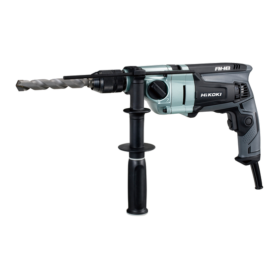
PRODUCT NAME
Hitachi 22 mm Impact Drill
DV 22V
Model
Hitachi 20 mm Impact Drill
DV 20VD
Model
CONTENTS
REPAIR GUIDE ---------------------------------------------------------------------------------------------------------------- 1
1. Precautions on disassembly and reassembly ----------------------------------------------------------- 1
STANDARD REPAIR TIME (UNIT) SCHEDULES ------------------------------------------------------------------ 14
LIST Nos.
DV 22V: F431
DV 20VD: F430
Jul. 2015
Page
DV 22V
Overseas Sales Division
Advertisement
Table of Contents

Related Manuals for Hitachi DV 22V


Summary of Contents for Hitachi DV 22V
- Page 1 LIST Nos. DV 22V: F431 DV 20VD: F430 Jul. 2015 PRODUCT NAME Hitachi 22 mm Impact Drill DV 22V Model Hitachi 20 mm Impact Drill DV 20VD Model CONTENTS Page REPAIR GUIDE ---------------------------------------------------------------------------------------------------------------- 1 1. Precautions on disassembly and reassembly ----------------------------------------------------------- 1...
-
Page 2: Repair Guide
1. Precautions on disassembly and reassembly [Bold] numbers in the description below correspond to the item numbers in the parts lists and exploded assembly diagrams for the Models DV 22V and DV 20VD. Disassembly 1. Removal of the drill chuck The Drill Chuck [3] is secured to Spindle (A) [4] with the 1/2”-20 UNF right-handed screw and Flat Hd. - Page 3 (2) Hold Spindle (A) [4] with an open-end wrench secured to the vise as shown in Fig. 2. Mount a pipe onto the hex. bar wrench. Turn the hex. bar wrench counterclockwise to loosen the Drill Chuck [3]. Fig. 2 • Removal of the drill chuck Turn it counterclockwise.
- Page 4 Fig. 4-1 • Removal of the click plate [43] Small flat-blade screwdriver Insert the tip of a flat-blade screwdriver into the clearance between Housing (B) [43] and Click Plate [44], and pry the arm of the Click Plate [44] off. [44] [52] Fig.
- Page 5 4. Removal of the carbon brush Cut the Band [45] that binds the Internal Wire [54] or [56] to the pigtail of the Carbon Brush [46] with nippers. Then disconnect the terminal of the Carbon Brush [46] from the terminal of the Brush Holder [52], and take out the Carbon Brush [46].
- Page 6 Fig. 6 • Removal of the armature Push. [20] Pinion of the armature Cylindrical Jig (73 mm in dia.) [35] Fig. 7-1 • Disassembly of the gear cover section Push. [12] Cylindrical Jig (38 mm in dia.) Fig. 7-2 • Removal of the shift lever ass'y Push.
- Page 7 Reassembly Reassembly can generally be conducted by reversing the disassembly procedure. However, special attention should be given to the following items. 1. Internal wire arrangement (1) Perform wiring of the internal wires according to Fig. 11 to Fig. 16. (2) Be careful not to get the internal wires caught between handle covers (A) and (B). 2.
-
Page 8: Lubrication Points And Type Of Lubricant
Fig. 9 • Reassembly of gear cover (A) ass’y (without slip clutch) [26] [29] [31] [15] [30] [14] [13] [21] [24] [32] [28] Fig. 10 • Reassembly of gear cover (A) ass’y [31] [30] [22] [32] Lubrication points and type of lubricant Apply Cosmo Molybdenum No. -
Page 9: Screw Tightening Torque
After no-load operation for 30 minutes, the no-load current values should be as follows: Voltage 110 V 120 V 127 V 220 V 230 V 240 V 4.0 A 2.0 A 1.9 A 1.9 A DV 22V Current max. 3.8 A 3.1 A 3.2 A 1.8 A 1.7 A 1.7 A DV 20VD... -
Page 10: Connecting Diagrams
Connecting diagrams Fig. 11 • Circuit diagram for the Models DV 22V and DV 20VD with noise suppressor and ferrite core Speed control switch Reversing switch Stator Black or brown Yellow White Noise suppressor Ferrite core Cord Blue White or blue... - Page 11 Fig. 13 • Wiring diagram for the Models DV 22V and DV 20VD with noise suppressor and ferrite core Carbon Brush [46] Spring [47] Stator [38] (Black internal wire) Stator [38] (White internal wire) Switch [55] Internal Wire [56] (Red)
- Page 12 Fig. 14 • Wiring diagram for the Models DV 22V and DV 20VD without noise suppressor and ferrite core Carbon Brush [46] Spring [47] Stator [38] (Black internal wire) Stator [38] (White internal wire) Switch [55] Internal Wire [56] (Red)
- Page 13 Fig. 15 • Wiring diagram for the Models DV 22V and DV 20VD Wiring of the reversing switch Wiring of the speed control switch Cord (black or brown) Cord (white or blue) (1 ) (2 ) Internal wire (blue) Stator (white)
- Page 14 Fig. 16 • Wiring diagram for the Models DV 22V and DV 20VD Fit the internal wire in the groove of the handle cover. Be careful not to catch the red and yellow internal wires passed under the switch. Position the rotational change lever of the switch between the protrusions of the Brush Holder [52].
-
Page 15: Standard Repair Time (Unit) Schedules
STANDARD REPAIR TIME (UNIT) SCHEDULES Variable Model 60 min. Fixed Work Flow DV 22V DV 20VD Housing (B) Guide (B) Stator Stator Holder General Assembly Armature Ball Bearing (607VV) Ball Bearing (608DD) Inner Cover Change Shaft Second Pinion Spindle (A) - Page 16 LIST NO. F431 IMPACT DRILL 2015 · 7 · 6 Model DV 22V (E1)
- Page 17 PARTS DV 22V ITEM DESCRIPTION REMARKS CODE NO. USED 995344 FLAT HD. SCREW (A) (LEFT HAND) M6 X 25 987576 CHUCK WRENCH FOR 13VLB-D,13VLR-D FOR SIN,MAL,UAE,CHN 321814 DRILL CHUCK 13VLRB-D INCLUD.1,2 FOR SIN,MAL,UAE,CHN 319546 DRILL CHUCK 13VLRE-N (KEYLESS TYPE) 338738...
-
Page 18: Standard Accessories
PARTS DV 22V ITEM CODE NO. DESCRIPTION REMARKS USED 331759 BAND 999088 CARBON BRUSH (1 PAIR) 339292 SPRING 338760 BRUSH COVER 338753 HANDLE COVER (B) NAME PLATE 301653 TAPPING SCREW (W/FLANGE) D4 X 20 (BLACK) 338759 BRUSH HOLDER 338752 HANDLE COVER (A) - Page 19 LIST NO. F430 IMPACT DRILL 2015 · 7 · 6 Model DV 20VD (E1)
- Page 20 PARTS DV 20VD ITEM DESCRIPTION REMARKS CODE NO. USED 995344 FLAT HD. SCREW (A) (LEFT HAND) M6 X 25 987576 CHUCK WRENCH FOR 13VLB-D,13VLR-D EXCEPT FOR NZL,GBR,SAF,RUS,EUROPE 321814 DRILL CHUCK 13VLRB-D INCLUD.1,2 319546 DRILL CHUCK 13VLRE-N (KEYLESS TYPE) FOR NZL,GBR,SAF,RUS,EUROPE 338738 SPINDLE (A) 939556...
- Page 21 PARTS DV 20VD ITEM CODE NO. DESCRIPTION REMARKS USED 338750 STATOR HOLDER 607VVC BALL BEARING 607VV 931701 BEARING LOCK 338749 HOUSING (B) 338761 CLICK PLATE 331759 BAND 999088 CARBON BRUSH (1 PAIR) 339292 SPRING 338760 BRUSH COVER 338753 HANDLE COVER (B) NAME PLATE 301653 TAPPING SCREW (W/FLANGE) D4 X 20 (BLACK)
Need help?
Do you have a question about the DV 22V and is the answer not in the manual?
Questions and answers