Pfaff 1245 Instruction Manual
Pfaff sewing machines
Hide thumbs
Also See for 1245:
- Instruction manual (82 pages) ,
- Instruction book (26 pages) ,
- Instruction manual (78 pages)

Related Manuals for Pfaff 1245


Summary of Contents for Pfaff 1245
-
Page 1: Instruction Manual
1245 1246 Instruction manual This instruction manual applies to machines from the following serial numbers onwards: PFAFF 1245 # 527 678 PFAFF 1246 # 527 679 296-12-18 401/002 Betriebsanleitung engl. 10.00... - Page 2 This Instruction manual is valid for all models and subclasses listed in the chapter „Specifications“ . The reprinting, copying or translation of PFAFF Instruction Manuals, whether in whole or in part, is only permitted with our previous permission and with written reference to the source.
-
Page 3: Table Of Contents
Specialist personnel ..................... 1 - 3 Danger ......................... 1 - 4 Proper use ........................2 - 1 Specifications ......................3 - 1 PFAFF 1245 ......................... 3 - 1 Possible models and subclasses ................. 3 - 1 Max. number of stitches/min 3 - 2 .............................. - Page 4 Inserting the bobbin case / Adjusting the bobbin thread tension ......... 9 - 3 Threading the needle thread / Adjusting the needle thread tension in the PFAFF 1245 ..........9 - 5 Threading the needle thread / Adjusting the needle thread tension in the PFAFF 1246 ..........9 - 6 Care and maintenance ....................
- Page 5 .04.13 Needle thread tension release ................... 11-15 .04.14 Thread check spring ....................11-16 .04.15 Thread check spring on PFAFF 1246 with thread trimmer -900/56 ......11-17 .04.16 Bobbin winder ......................11-18 .04.17 Presser-foot pressure ....................11-19 Adjusting the thread trimmer -900/56 ................ 11-20 .05.01...
-
Page 6: Safety
Safety Safety 1.01 Directives This machine is constructed in accordance with the European regulations contained in the conformity and manufacturer’s declarations. In addition to this Instruction Manual, observe also all generally accepted, statutory and other regulations and legal requirements -including those of the country and all valid environ- mental protection regulations! The regionally valid regulations of the social insurance society for occupational accidents or other supervisory organisations are to be strictly adhered to! -
Page 7: Safety Symbols
It is the obligation of the operator to ensure that none of the safety mechanisms are removed or deactivated. It is the obligation of the operator to ensure that only authorized persons operate and work on the machine. Further information can be obtained at your PFAFF agent. 1 - 2... -
Page 8: Operating And Specialist Personnel
Safety 1.05 Operating and specialist personnel Operating personnel .05.01 Operating personnel are persons responsible for the equipping, operating and cleaning of the machine as well as taking care of faults arising in the sewing area. The operating personnel is obliged to observe the following points and must: always observe the Notes on Safety in the Instruction Manual! never use any working methods which could limit the level of safety in using the machine! -
Page 9: Danger
Safety Danger A working area of 1 metre is to be kept free both in front of and behind the machine while it is in operation so that it is always easily accessible. Never reach into the sewing area while sewing! Danger of injury by the needle! Never leave objects on the table or in the needle plate area while adjusting the machine settings! Objects can become trapped or be slung away! Danger of injury! - Page 10 Safety Do not operate the machine without tilt-back safeguard 3! Danger of crushing between upper part and table top! Fig.1 - 02 Do not operate the machine without belt guards 4 and 5! Danger of injury by the revolving V-belt! Fig.
-
Page 11: Proper Use
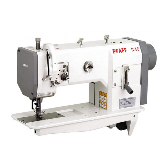
Proper use Proper use PFAFF 1245 The PFAFF 1245 is a single needle, flatbed sewing machine with bottom, top and needle feeds as well as a large vertical hook for sewing lockstitch seams. The machine is designed for commercial use (industry). -
Page 12: Specifications
Specifications Specifications PFAFF 1245 Stitch type: ......................301 (lockstitch) Needle system: ......................134-35 Needle thickness in 1/100 mm: Model C: ........................110 - 140 Max. thread thickness (synthetic Model C: ........................... 20/3 Max. stitch length: Model N: ........................6.0 mm Model N8: ........................ -
Page 13: Max. Number Of Stitches/Min -1
Specifications Max. number of stitches/min Top feed lift Max. number of Max. number of stitches/min stitches/min for stitch stitch lengths up to 6 mm lengths from 6 mm to 8 mm less than 3.5 mm 2800 2600 from 3.5 to 5.5 mm 2500 2500 from 5.5 to 7 mm... -
Page 14: Pfaff 1246
Specifications PFAFF 1246 Stitch type: ......................301 (lockstitch) Needle system: ......................134-35 Needle thickness in 1/100 mm: Model B: ........................80 - 100 Model C: ........................110 - 140 Max. thread thickness (synthetic Model B: ........................... 40/3 Model C: ........................... 20/3 Max. -
Page 15: Max. Number Of Stitches/Min
Specifications Max. number of stitches/min less than 3.5 mm 2500 2300 2700 2500 from 3.5 to 5.5 mm 2400 2100 2400 2200 from 5.5 to 7 mm 1900 1600 1900 1700 3 - 4... -
Page 16: Disposal Of The Machine
Disposal of the machine Disposal of machine waste The proper disposal of machine waste is the responsibility of the customer. The materials used on the machines are steel, aluminium, brass and various plastics. The electrical equipment consists of plastics and copper. The machine waste is to be disposed of in accordance with the locally valid environmental protection regulations. -
Page 17: Transport Packaging And Storage
Transport packaging and storage Transport packaging and storage Transport to the customer’s premises Within the Federal Republic of Germany, the machine is delivered without packaging. Machines for export are packaged in a crate or wrapped depending on how they are transported. -
Page 18: Explanation Of The Symbols
Explanation of the symbols Explanation of the symbols In the following section of this Instruction Manual, certain tasks or important pieces of information are accentuated by symbols. The symbols used have the following meanings: Note, information Cleaning, care Lubrication, greasing Servicing, repairing, adjustment, maintenance (only to be carried out by specialist personnel) 6 - 1... -
Page 19: Controls
Controls Controls On/off switch Turn the machine on and off by switching the on/off switch 1 on and off. When the machine is on, the light in the switch is also on. The switch in the illustration can be found on machines with Quick motors. -
Page 20: Pedal (On Machines With Automatic Presser-Foot Lifter (Subclass -910/98)
Controls Pedal (on machines with automatic presser-foot lifter -910/98) With the on/off switch on 0 = Machine stop +1 = Sew - 1 = Raise presserfoot - 2 = Trim thread (on machines with thread trimmer) Fig. 7 - 03 Key on the machine head (for machines with backtacking mechanism -911/97) Switch to reverse sewing by pressing... -
Page 21: Lever For Lifting The Presser Foot
Controls Lever for lifting the presser foot The sewing foot can be lifted by raising lever 1. Fig. 7 - 05 Feed regulator / reverse sewing Adjust the stitch length by turning the knurled nut 1 accordingly. Reverse sewing Press knurled nut 1 upwards as far as possible (position „R“). -
Page 22: Feed Regulator On Machines With Backtacking Mechanism -911/97
Controls Feed regulator (on machines with backtacking mechanism -911/97) You can set the length of the reverse stitch as large as is required, independent of the forward stitch. The forward stitch is set with knurled screw 1 and the reverse stitch with knurled screw 2. -
Page 23: Mounting And Commissioning The Machine
Mounting and commissioning the machine Mounting and commissioning the machine The machine must only be mounted and commissioned by qualified personnel! All relevant safety regulations are to be observed! If the machine is delivered without a table, it must be ensured that the frame and the table top which you intend to use can hold the weight of the machine and the motor, even while sewing. -
Page 24: Adjusting The V-Belt Tension
Mounting and commissioning the machine Adjusting the V-belt tension 01.02 Loosen nuts 1. Tighten the V-belt with belt take-up hanger 2. Tighten nuts 1. Fig. 8 - 02 Fig. 8 - 02 shows a Quick motor. If another motor is used, proceed as described in the motor’s instruction manual. -
Page 25: Mounting The Lower V-Belt Guard
Mounting and commissioning the machine Mounting the lower V-belt guard .01.04 Align belt-guard 7 in such a way that both the motor pulley and the V-belt run freely. Tighten screws 8. Fig. 8 - 04 Fig. 8 - 04 shows a Quick motor. If another motor is used, proceed as described in the motor’s instruction manual. -
Page 26: Mounting The Spool Holder
Mounting and commissioning the machine Mounting the spool holder .01.06 Mount the spool holder as shown in Fig. 8 - 05. Insert spool holder in the table-top hole and fasten it by means of the included nuts. Fig. 8 - 05 Mounting the sewing lamp 01.07 Screw the sewing lamp onto the table top (wood screws 5x35) and have it connected by... -
Page 27: Commissioning The Machine
Mounting and commissioning the machine Commissioning the machine Before commissioning the machine, check the electrical leads and pneumatic hoses for any damage. Remove pin 1 of the oil reservoir 2 (Fig. 8 - 06). The pin serves only to protect the machine from damage during transport and must not be used when sewing. -
Page 28: Preparation
Before all preparation work, the machine is to be switched off via the on/off switch or to beseparated from the electricity supply by removing the plug from the mains! Inserting the needle in the PFAFF 1245 Turn the machine off! Use only system 134 - 35 needles! Loosen needle retaining screw 1. -
Page 29: Inserting The Needle In The Pfaff 1246
Preparation Inserting the needle in the PFAFF 1246 Turn the machine off! Use only system 134 - 35 needles! Loosen needle retaining screws 1. Insert needles as far as it will go (the longitudinal needle groove of the left-hand needle must be pointing to the right and that of the right-hand needle to the left). -
Page 30: Winding The Bobbin Thread, Adjusting The Thread Tension
Preparation Winding the bobbin thread, adjusting the thread tension Fig. 9 - 02 Place an empty bobbin 1 onto bobbin shaft 2. Thread the bobbin in accordance with Fig. 9 - 02 and wind it clockwise around bobbin 1 a few times. Switch on the bobbin winder while at the same time pressing bobbin winder spindle 2 and lever 3. -
Page 31: Removing/Threading The Bobbin Case
Preparation Removing/Threading the bobbin case Turn the machine off! Removing the bobbin case. Open the bed slide. Raise latch 1 and remove bobbin case 2. Inserting the bobbin case. Insert bobbin case 2 so that it clicks into place. Close latch 1 and close the bed slide. Fig. -
Page 32: Threading The Needle Thread
Preparation Threading the needle thread / Adjusting the needle thread tension in the PFAFF 1245 Fig. 9 - 05 Turn the machine off! Thread the machine as shown in Fig. 9 - 05. Take note that the needle is threaded from the left (see arrow). -
Page 33: Adjusting The Needle Thread Tension In The Pfaff 1246
Preparation Threading the needle thread / Adjusting the needle thread tension in the PFAFF 1246 Fig. 9 - 06 Maschine ausschalten! Thread the machine as shown in Fig. 9 - 06. Care must be taken that the left-hand needle is threaded from the right and the right-hand needle is threaded from the left. -
Page 34: Care And Maintenance
Care and maintenance Care and maintenance Servicing and maintenance intervals Check the air pressure ................daily before use Clean the hook compartment ......daily, more often if in continuous operation Check the water container of the air filter ..........daily before use General lubrication .................. -
Page 35: General Lubrication
Fig. 10 - 02 Only use oil with a mean viscosity of 22.0 mm /s at 40°C and a density of 0.865 g/cm at 15°C. We recommend PFAFF sewing machine oil. Part no. 280-1-120 144. Fig. 10 - 03 10 - 2... -
Page 36: Lubricating The Hook
Care and maintenance Turn the machine off! Lubricate all bearings marked in Fig. 10.02 twice a week. Open the bed slide to gain access to oiling point 1. Pull the knee lever out to the front and lay the machine on its back. Lubricate all bearings marked in Fig. -
Page 37: Lubricating The Head
Only use oil with a mean viscosity of 22.0 mm /s at 40°C and a density of 0.865 g/cm at 15°C. We recommend PFAFF sewing machine oil. Part no. 280-1-120 144. Fig. 10 - 05 Lubricating the top-feed drive excentric... -
Page 38: Checking The Air Pressure
Care and maintenance Checking the air pressure Before each use of the machine, check the air pressure on gauge 1. The gauge must display a pressure of 6 bar. If necessary, alter the pressure to this level. To do so, lift button 2 and turn it so that the gauge shows a pressure of 6 bar. -
Page 39: Adjustment
Adjustment Adjustment The illustrations in this section show the PFAFF 1245 single-needle machine. For the PFAFF 1246 two-needle machine, various adjustments must be made twice, i.e. to the left- and right-hand sewing hooks. This will be pointed out in the respective sections, whereby it is often possible to apply the mirror image of the illustrations. -
Page 40: Adjusting The Basic Machine
Adjustment Adjusting the basic machine Positioning the feed dog across the direction of sewing 04.01 Requirement The bottom feed dog must be the same distance from the left and right side of the needle- plate cutout. Fig. 11 - 01 Loosen screws 1 and 2. -
Page 41: Positioning The Feed Dog In The Direction Of Sewing
Adjustment Positioning the feed dog in the direction of sewing 04.02 Requirement With the longest stitch set, the bottom feed dog must have the same clearance the front and the back with respect to the needle-plate cutout when feeding both forwards and backwards. -
Page 42: Height Of The Bottom Feed-Dog
Adjustment 11.04.03 Height of the bottom feed-dog Requirement With the stitch length set at „0“ , the bottom feed dog must protrude over the needle plate as high as the teeth when at TDC. Fig. 11 - 03 Set stitch length „0“ . Bring the bottom feed dog to its TDC by turning the handwheel. -
Page 43: Pre-Adjusting The Needle Height
Adjustment Pre-adjusting the needle height 04.04 Requirement With the needle bar at BDC, the distance between the needle bar and the needle plate must be 15 mm. 15 mm Fig. 11 - 04 Move needle bar 1 (screw 2) in accordance with the requirement without moving it laterally. -
Page 44: Centering The Needle In The Needle Hole
Adjustment Centering the needle in the needle hole 04.05 Requirement With the stitch length set at „0“ , the needle must enter the needle hole exactly in the middle. Fig. 11 - 05 Unscrew vibrating presser 1 and presser foot 2. Set stitch length „0“... -
Page 45: Lifting Motion Of The Bottom Feed-Dog
Adjustment Lifting motion of the bottom feed-dog 04.06 This adjustment does not apply for machines without a bottom feed lifting phase (without P). Requirement 1. With the needle bar at its BDC, the bottom feed dog must be at its TDC. 2. -
Page 46: Driving Motion Of The Bottom And Top Feeds
Adjustment Driving motion of the bottom and top feeds 04.07 Requirement With the longest stitch length set and the needle bar at its BDC, the top and bottom feeds should not move when the reverse-feed lever is activated. Fig. 11 - 07 Set the longest stitch. -
Page 47: Hook-To-Needle Clearance, Needle Rise, Needle Height And Needle Guard
Adjustment Hook-to-needle clearance, needle rise, needle height and needle guard 04.08 (On Model 1246 make these adjustments on both sewing hooks.) Requirement With the stitch length set at „3“ and the needle rise at (1.8 mm after BDC of the needle bar on model „B“... - Page 48 Adjust the needle height in accordance with requirement 2 (see also chapter 11.04.04). Align needle guard 7 in accordance with requirement 3. Bei der PFAFF 1246 ist nach Veränderung des Nadelabstandes unbedingt die Verbindungsstange zum Fadenabschneider (siehe auch Kap.11.05.10) neu zu justieren.
-
Page 49: Top-Feed Stroke
Adjustment Top-feed stroke 04.9 Requirement At the largest top-feed stroke setting and stitch length „0“ , presser foot 1 and vibrating presser foot 2 must lift 7.0 mm from the needle plate when the handwheel is turned. 7 mm 7 mm Fig. -
Page 50: Lifting Motion Of The Top Feed
Adjustment Lifting motion of the top feed 04.10 Requirement When presser foot 1 is resting on the needle plate, the vibrating presser foot 4 and the point of the needle must both reach the needle plate at the same time when the top feed stroke is set at maximum. -
Page 51: Bobbin-Case Opener
Adjustment Bobbin-case opener 04.11 (On Model 1246 make these adjustments on both bobbin openers.) Requirement The needle thread must not be clamped between the bobbin-case opener 1 and the bob- bin-case base 3 nor may it be clamped between projection 4 and the retaining trip of the needle plate (see arrows). -
Page 52: Safety Clutch
Adjustment Safety clutch 04.12 The safety clutch is set by the manufacturer and screws 5 are sealed. If the thread jams, the safety clutch snaps out to prevent damage to the hook. A description of how to snap the clutch back in follows. Fig. -
Page 53: Needle Thread Tension Release
Adjustment Needle thread tension release 04.13 Requirement With the presser foot raised, both of the tension discs must be at least 0.5 mm apart. The clearance of 0.5 mm is a minimum and can increase to more than 1 mm when using thick threads. -
Page 54: Thread Check Spring
Adjustment Thread check spring 04.14 Requirement The movement of thread check spring 2 must be finished when the needle point enters the material (approx. 7 mm spring path). Due to technical reasons, the length of the thread-check spring path can vary a little in either direction. -
Page 55: Thread Check Spring On Pfaff 1246 With Thread Trimmer -900/56
Adjustment Thread check spring on PFAFF 1246 with thread trimmer -900/56 04.15 Requirement The motion of thread controller springs 1 and 6 should cease as soon as the needle point penetrates the material (= about 7 mm spring deflection). Due to technical reasons, the length of the thread-check spring path can vary a little in either direction. -
Page 56: Bobbin Winder
Adjustment Bobbin winder 04.16 Requirement 1. With the bobbin winder switched on, the bobbin winder spindle must engage reliably. With the bobbin winder switched off, friction wheel 5 must not touch drive wheel 1. 2. The bobbin winder must switch off automatically when the thread level is approximately 1 mm from the edge of the bobbin. -
Page 57: Presser-Foot Pressure
Adjustment Presser-foot pressure 04.17 Requirement The material must be fed reliably even at top sewing-speed. There mustn’t be pressure marks on the material. Fig. 11 - 16 Turn screw 1 in accordance with the requirement. 11 - 19... -
Page 58: Adjusting The Thread Trimmer -900/56
Adjustment Adjusting the thread trimmer -900/56 Pre-adjusting the control cam 05.01 Requirement 1. The eccentric bearing-surface of control cam 5 must be laterally in the middle of pawl 8. 2. With the take-up lever at its TDC, the beginning of the largest eccentricity of the bearing surface (in the direction of rotation) must be underneath the point of pawl 8. -
Page 59: Tripping Lever
Adjustment Tripping lever 05.02 Requirement In needle rise position, the flattened pin of control lever 6 (see arrow) must fall slightly into the track of control cam 7 when activating lever 8 is activated. Fig. 11 - 18 Screw out screw 1 and swing out connecting rod 2. Loosen screws 3 and 4. -
Page 60: Pawl
Adjustment Pawl 05.03 Requirement With the cut-off mechanism in resting position, there must be a distance of 0.3 mm between the largest eccentricity of bearing surface 1 and pawl 2. 0.3 mm Fig. 11 - 19 Position the largest eccentricity of bearing surface 1 underneath pawl 2 by turning the handwheel. -
Page 61: Engaging Solenoid
Adjustment Engaging solenoid 05.04 Requirement In needle rise position and with engaging solenoid 5 activated, there must be a distance of 0.3 mm between engaging lever 2 and pawl 3. 0.3 mm Fig. 11 - 20 Bring the machine to needle rise position by turning the handwheel. Loosen screw 1 until the engaging solenoid can be turned with difficulty. -
Page 62: Release Trip
Adjustment Release trip 05.05 Requirement In needle rise position and with control lever 4 engaged, there must be a distance of approx. 0.3 mm between the bolt of the control lever and the base of the cam track. 0.3 mm Fig. -
Page 63: Engaging Lever
Adjustment Engaging lever 05.06 Requirement With the needle bar at TDC and with control lever 3 at starting position, there must be a distance of approx. 0.3 mm between bolt 4 and the outer diameter of control cam 5. Fig. 11 - 22 Bring the needle bar to TDC by turning the handwheel. -
Page 64: Linkage Rod
Adjustment Linkage rod 05.07 Requirement When shaft 9 begins its sliding motion, lever 6 must simultaneously lift from stop 7. Fig. 11 - 23 Affix spherical head 1 to control lever 3 using screw 2. Loosen nuts 4 (right and left handed thread). Bring the machine to needle rise position by turning the handwheel and activate engaging lever 5. -
Page 65: Final Adjustment Of The Control Cam
Adjustment Final adjustment of the control cam 05.08 Requirement When control lever 3 is engaged and the needle point is 12 mm above the needle plate coming from its BDC, the motion of the thread catcher 5 must begin. Fig. 11 - 24 Bring the take-up lever to just past its TDC by turning the handwheel and loosen the accessible screws on control cam 1. -
Page 66: Catch
Adjustment Catch 05.09 Requirement With the cut-off mechanism in resting position, there must be a distance of approx. 5 mm between catch 1 and control lever 6. 5 mm Fig. 11 - 25 Lightly affix catch 1 and cover plate 2 using screws 3. Move catch 1 as far as possible in the direction of the arrow and then move it laterally in accordance with the requirement. -
Page 67: Connecting Rod (For Pfaff 1246 Only)
Adjustment Connecting rod (for PFAFF 1246 only) 05.10 Requirement When the cutting device is in the off-position, the length of spacer rod 4 should be equal to the distance between shafts 2 and 3. Fig. 11 - 25a Loosen nuts 1 (right- and left-hand thread) when the cutting device is in the off-position. -
Page 68: Thread-Catcher Height
Adjustment Thread-catcher height 05.11 (On Model 1246 make these adjustments on both thread catchers.) Requirement When thread catcher 2 is pushed forwards manually with the take-up lever at its TDC, the lower point of the thread catcher must pass 1 mm over the back of hook 4. 0,1 mm Fig. -
Page 69: Knife
Adjustment Knife 05.12 (On Model 1246 make these adjustments on both knives.) Requirement 1. The elongated hole of knife 3 must be parallel to knife carrier 5 and the knife must not be touching the casting (see arrow). 2. When the point of needle catcher 4 protrudes approx. 3 mm over the cutting edge of the knife, knife 3 must just touch thread catcher 4. -
Page 70: Thread Catcher Reverse Position
Adjustment Thread catcher reverse position 05.13 (On Model 1246 make these adjustments on both thread catchers.) Requirement At the front point of reversal of thread catcher 3, its rear edge must be flush with the cutting edge of knife 4 (see arrow). Fig. - Page 71 Adjustment In this position and taking care to ensure that there is no horizontal play, tighten screw 1. 11 - 33...
-
Page 72: Bobbin-Thread Clamp Spring
Adjustment Bobbin-thread clamp spring 05.14 (On Model 1246 make these adjustments on both clamp springs.) Requirement 1. Between clamp spring 5 and the bottom of thread catcher 4, there must be a distance of 0.3 mm. 2. At the front point of reversal of thread catcher 4, the points of clamp spring 5 must be flush with the back edge of catcher 4 (see arrow). - Page 73 Adjustment Bring the machine to needle rise position, activate the engaging lever and bring the thread catcher to its front point of reversal by turning the handwheel. Align clamp spring 5 (screws 6) in the elongated hole in accordance with requirement 2 - if necessary carrier 1 (screws 2) as well.
-
Page 74: Tension Release Bar
Adjustment Tension release bar 05.15 Requirement 1. With the cut-off mechanism in resting position and the presser foot raised, there must be a distance of approx. 7 mm between the left edge of release bar 8 and housing 9. 2. When the point of thread catcher 5 is at the same height as the rear edge of stop trip 6 of the needle plate (see arrow) with the presser foot resting on the needle plate, the tension discs must be loosened to such an extent that the needle thread can be easily pulled through them. - Page 75 Adjustment Allow the presser foot to rest on the needle plate. By continuing to turn the handwheel, position the point of thread catcher 5 at the same height as the edge of rear stop trip 6 of the needle plate and press release bar 8 to the left in accordance with requirement 2 using retaining collar 7.
-
Page 76: Positioner
Adjustment Positioner 05.16 Requirement When interrupting the sewing process, the machine must position itself at approx. 4 mm after the BDC of the needle bar. After trimming the thread, the machine must position itself at the TDC of the take-up lever. Carry out the adjustment as stipulated in the instruction manual of the motor. -
Page 77: Wearing Parts
91-100 366-15 91-000 425-15 (2x) 91-000 407-15 (2x) 11-108 093-15 91-173 664-15 (2x) 11-330 082-15 11-174 089-15 System 134-35 PFAFF 1245; 1246 PFAFF 1245-900; 1246-900 91-140 538-91(Version B) 91-140 540-91(Version B) 91-140 539-91(Version C) 91-140 451-91(Version C) 91-000 390-05 91-000 390-05... - Page 78 91-140 726-01 11-130 089-15 (2x) 91-018 885-15 11-130 089-15 (2x) 91-018 147-05 PFAFF 1245; 1246 91-010 937-05 (1245 Version C) 91-010 179-05 (1246 Version B) 91-015 519-05 (1246 Version C) PFAFF 1245-900; 1246-900 91-176 328-05 91-176 328-05 12 - 2...
- Page 79 Notes...
- Page 80 G.M. PFAFF KAISERSLAUTERN I N D U S T R I E M A S C H I N E N Postfach 3020 D-67653 Kaiserslautern Königstr. 154 D-67655 Kaiserslautern Telefon: (0631) 200-0 Telefax: (0631) 17202 E-Mail: info@pfaff-industrial.com Gedruckt in der BRD Printed in Germany Imprimé...
Need help?
Do you have a question about the 1245 and is the answer not in the manual?
Questions and answers