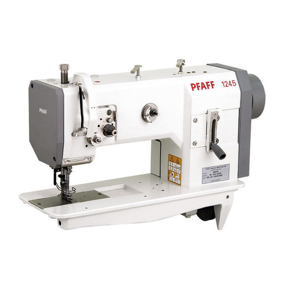
Pfaff 1245 Instruction Manual
Hide thumbs
Also See for 1245:
- Instruction manual (82 pages) ,
- Instruction book (26 pages) ,
- Instruction manual (36 pages)
Advertisement
Quick Links
Advertisement

Summary of Contents for Pfaff 1245
- Page 1 1245 1246 Instruction manual 2962-17 841 Betriebsanleitung engi. 10.97...
- Page 2 _______...
- Page 5 ‘1...
- Page 9 Fig. 1 -01...
- Page 10 Do not operate the machine without tilt-back safeguard 3! Danger of crushing between upper part and table top! Do not operate the machine without belt guards 4 and 5! Danger of injury by the revolving V-belt! 1-03...
- Page 14 Subject to alteratio n • Or compar able thicknes ses of other thread types “...
-
Page 16: Disposal Of The Machine
Disposal of the machine Disposal of machine waste • The proper disposal of machine waste is the responsibility of the customer. • The materials used on the machines are steel, aluminium, brass and various plastics. The electrical equipment consists of plastics and copper. •... -
Page 24: Mounting And Commissioning The Machine
Mounting and commissioning the machine 8.01.02 Adjusting the V-belt tension • Loosen nuts 1. • Tighten the V-belt with belt take-up hanger 2. • Tighten nuts 1. Fig. 8 02 02 shows a Quick motor. If another motor is used, proceed as describE Fig. - Page 33 Preparation Threading the needle thread / Adjusting the needle thread tension in the 9.07 PFAFF 1246 — Fig. 9 — Maschine ausschalten! 06. Care must be taken that the left-hand needle • Thread the machine as shown in Fig. 9 is threaded from the right and the right-hand needle is threaded from the left.
- Page 51 Bobbin-case opener 11.04.11 (On Model 1246 make these adjustments on both bobbin openers.) Requirement The needle thread must not be clamped between the bobbin-case opener 1 and the bob bin-case base 3 nor may it be clamped between projection 4 and the retaining trip of the needle plate (see arrows).
- Page 61 11 .05.04 Engagin g solenoid Requirem ent In needle rise position and with engaging solenoid 5 activated, there must be a distance of 0.3 mm between engaging lever 2 and pawl Fig. 11 • Bring the machine to needle rise position by turning the handwheel. •...
- Page 65 Fg 1124...
- Page 69 Adjustment Knife 11.0512 Modes 1246 make these adjustments on both knives.) Requirement 1. The elongated hole of knife 3 must be parallel to knife carrier 5 and the knife must not be touching the casting (see arrow). 2. When the point of needle catcher 4 protrudes approx. 3 mm over the cutting edge of the knife, knife 3 must just touch thread catcher 4.
- Page 73 §u!J apaau ‘uoiisod au!!pew iUoJ peeiq 6u!JdS SMeJOS) pöuoe 9DUepJODDe L4IJM sMais) esseeu JJJD UO!!SOd 6UDf einsue J81JJeD euiqw ue1lb! V6-U ____...


Need help?
Do you have a question about the 1245 and is the answer not in the manual?
Questions and answers