
Related Manuals for Alfa Plam Alfa 9


Summary of Contents for Alfa Plam Alfa 9
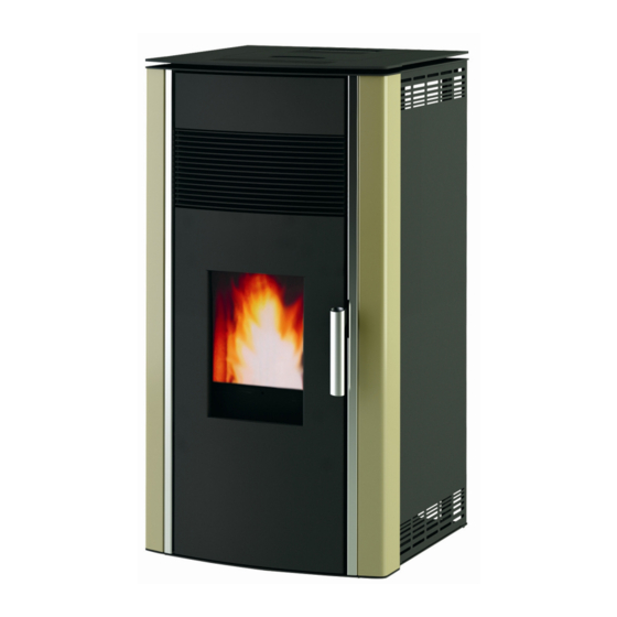
- Page 1 PELLET STOVE „ALFA 9” INSTRUCTION MANUAL FOR INSTALLATION, HANDLING AND MAINTENANCE OF THE STOVE Pellet → wood biomass fuel → biofuel...
-
Page 2: Technical Characteristics Of The Stove
These goals are entirely achieved with principle of pure combustion, so for this reason the company ALFA PLAM has founded the design of its products on that basis. -
Page 3: Purpose Of This Instruction
These instructions represent a real piece of art at the moment when they are launched at the market. For this reason the company ALFA PLAM does not take into consideration the stoves which are already in the market with the corresponding technical documentation and considers them as deficient or inappropriate after any type of modification, adaptation and application of new technologies to newly launched devices. -
Page 4: Placement Of The Stove
− the internal cross section of the flue, the material it is made of, the balance of the cross section, to make sure there are no barriers and obstacles in the flue. − the height and vertical flue extension, − the altitude of the place of mounting, that is, the place of installation of the stove, −... -
Page 5: Smoke Exhaust System
If the path of smoke exhaust such that it creates bad draft, that is, bad air flow (numerous curves, inappropriate smoke exhaust end, narrowing etc.), the smoke exhaustion can be bad i.e. in such cases the smoke exhaustion is not the best really. The smoke exhaust system from the stove functions on the basis of negative pressure and slight pressure from the smoke outlet pipe. - Page 6 2. Insert a steel pipe in the flue, with a diameter of 10cm if you own elements for such correction of the flue. 3. By regulation of certain parameters in the stove. This regulation may be performed only by an authorized service of Alfa Plam. − Make sure that the connection to the house flue is properly sealed.
- Page 7 Figure 2 When you are using an external pipe between the stove and the smoke exhaust pipe, it is compulsory that you use one „T“ connection (joint) (as shown in figures 5 and 6), with a cover for cleaning (plug) by the stove. The application of these “T”...
- Page 8 WALL Z I D Ø100 REDUCIR O 1 0 0 P E Ć O 8 0 STOVE O 8 0 Ø80 T-RAČVA Figure 4 Figure 5 1. Reinforcement 80>100 2. Pipe reinforcement with a "T" shape Ø100 Ø80 Figure 6 1.
- Page 9 SMER DIMA Smoke direction Figure 7. Manner of installation of the flue pipe Diameter of the smoke exhaust pipe (mm) Thickness of the insulation D.80 D.100 Diameters of holes (openings) which should be made (mm) Walls made of wood, or in any case flammable, or parts that are flammable Concrete wall or roof Wall or roof of bricks...
-
Page 10: Connection To Power Supply
This opening must be made at the external wall of the room, that is, the room where the stove is located. Intake, that is, supply of air for combustion from the garage, the depository for burning materials or from the room where there is risk of fire is forbidden. The hole, that is, the opening of the external suction air for combustion must not be connected by means of pipe. - Page 11 We would like to inform the installer of the stove about some general instructions that he must adhere to, for proper installation i.e. for the purpose of proper mounting of the stove. These standards are required, but not entirely. For further and more precise information, it is required that you read the rest of this instruction manual.
- Page 12 The stove is a „heating device“ and during its operation it has surfaces which are very hot, that is, which have extremely high temperatures, or which are quite hot. This stove is made so that it burn fuel from pressed wood mass (pellets with a diameter from 6 mm to 7 mm, length from about 30 mm, maximal humidity of 8-9%).
- Page 13 Figure 11 Figure 12 Figure 13 6.1 ROUTINE CLEANING AND MAINTENANCE PERFORMED BY THE STOVE USER The use of a vacuum cleaner with a shell and tube shape can facilitate the cleaning of the stove. The vacuum cleaner must have a filter which prevents the vacuumed dust to go back in the room where the stove is located. Before you begin with routine maintenance, including cleaning, you should take over the follow precautions: −...
- Page 14 Always make sure that the stove and the ash are cold. This is a firebox (box-shaped) where the wood mass pellet combust. Look at figure 11. It is recommendable that the firebox is cleaned with a vacuum cleaner after each use (when the stove gets cold). After each third use, it is recommended to take out the firebox and to check to make sure that there is no too much ash which is accumulated on the bottom of the box-shaped firebox.
-
Page 15: Special Maintenance
− GENERAL CLEANING AT THE END OF THE HEATING SEASON Make sure that the stove and the ash are both cold – switch off the stove from the power supply At the end of the season, for safety purposes, switch of the stove from the power supply. It is very important to clean and check the stove, as explained in the points above. -
Page 16: Description And Functioning Of The Electronic Card
DANGER In the event of fire in the smoke exhaust pipe, keep all people and pets away from the room, immediately switch off the power supply by using the main switch in the house or by pulling the plug from the wall (the plug must always be easily reachable and free), and immediately call firemen. -
Page 17: Functioning Of The Electronic Card
LED snail ON State/power/title of parameter LED data reception by remote control LED chrono-active ON/OFF Increase of temperature Power increase Power reduction Reduction of temperature LED ambiental thermostat Set / menu LED modification for set temperatures State of display/time/temperature values of parameter Figure 17 Electronic keyboard of controls LED →... - Page 18 Figure 21. Upon termination of the stabilization stage (the standard duration is about 2 seconds), the control of the electronic unit goes to an operation mode, sowing the selected heating power (which may be changes by means of the buttons 5 and 6) and the ambient temperature Figure 22. Figure 22.
-
Page 19: Parameters Used By The Stove User
• Switching off of the stove occurs once you press button 4. The upper display shows the message OFF (switched off) and the flow of pellet fuel into the firebox is stopped. After cooling, the tangential fan switches off (stops working) and after 10 minutes from the moment of cooling, the suction device switches off as well. The switching off speed of the smoke suction device is a parameter which may be set only by an authorized repairman. -
Page 20: Alarm Management
Once you have adjusted and confirmed the operation of the clock, the LED lamp 1 (left, up) on the keyboard will switch on and will stay on. Temporarily recontrol the accuracy of the clock and if it is disrupted you can adjust it once again according to the manner described above. - Page 21 AttE Figure 23 9.4.1. Alarm dEP no (pressure alarm – alarm of the pressure switch) It occurs when irregularities occur related to: The flue pipe hardly pulls which causes poor, insufficient pressure. If the alarm continues occurring, check whether the stove of the flue should be serviced. The smoke pressure switch controls the negative pressure in the stove chamber due to improperly closed door or ash box, or due to some obstacles in the smoke outlet.
- Page 22 located in the lower back part, above the main switch (0-1) Figure 10 and then press the button 4 in a duration of 3 seconds until the stove returns back to it ON (switched on) position. The upper thermostat blocks the stove operation when the stove chamber heats at 180°...
- Page 23 By pressing the button 4 you can delete, that is, remove a message from the display. The alarm signals are followed by a sound signal. Figure 32. Electronic card 10.0. INFORMATION REGARDING DISPOSAL (THROWING OUT) AND DISASSEMBLY (SEPARATION) OF THE STOVE The disassembly and throwing out i.e.
-
Page 24: Table Of Contents
- the connection or the repair of the product was performed by an unauthorized persons, that is, if unoriginal parts have been embedded, - if the device has not been properly used in accordance with these guidelines, - if some mechanical damaging of the device occured during usage, - if the repairs of defects were performed by an unauthorized person, - if the device has been used for commercial purposes, - if the damage has occured during transportation after the device was sold,...
Need help?
Do you have a question about the Alfa 9 and is the answer not in the manual?
Questions and answers