Advertisement
Table of Contents
- 1 Service Manual
- 2 Circuit Description
- 3 Parts List for Front Board
- 4 Parts List for Main Pcb
- 5 Parts List for Pc00021 Ah 250 Rear Pcb
- 6 Bipolar Bear Output Stage Circuit Diagram
- 7 Bipolar Bear Pc00026 Circuit Description
- 8 Parts List for 300W Bass Amp
- 9 300W Output Circuit Diagram
- Download this manual
TRACE ELLIOT
SERVICE MANUAL
DATE :
Product Code:
Model Number :
This unit has used two issues of 300 watt MOSFET power board.
The Bi-polar Bear and the 300 Mosfet Board
Details for both are included in this manual.
You should check which board you have in your unit before
attempting any repair.
The Bi-polar board is marked PC00026
The MOSFET board is marked PC00083
December 29, 1999
N/A
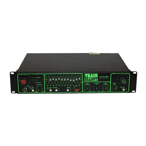
GP12 300 WATT SMX SERIES
Issued by:
Trace Elliot Limited
Blackwater Trading Estate
The Causeway
Maldon
Essex
England
CM4 4GG
Advertisement
Table of Contents

Related Manuals for TRACE ELLIOT GP12 SMX SERIES


Summary of Contents for TRACE ELLIOT GP12 SMX SERIES
-
Page 1: Service Manual
Details for both are included in this manual. You should check which board you have in your unit before attempting any repair. The Bi-polar board is marked PC00026 The MOSFET board is marked PC00083 Issued by: Trace Elliot Limited Blackwater Trading Estate The Causeway Maldon Essex England... -
Page 7: Parts List For Front Board
PARTS LIST FOR GP12SM FRONT BOARD Description Part Code Where Used RESISTORS 15K ¼ WATT 72-RM15K R169 R170 1K ¼ WATT 72-RM1K R174 R176 1K3 ¼ WATT 72-RM1K3 R172 1K5 ½ WATT 72-RM1K5-.5W R173 4K7 ¼ WATT 72-RM4K7 R171 6K8 ¼ WATT 72-RM6K8 R168 430R 2.5 WATT... -
Page 8: Parts List For Main Pcb
PARTS LIST FOR GP12SM MAIN PCB Description Part Code Where Used RESISTORS 3M9 ¼ Watt 72-RM3M9 R1 R3 R5 47K ¼ Watt 72-RM47K R15 R17 R51 R55 R61 R64 R65 R68 R122 R123 R143 10K ¼ Watt 72-RM10K R4 R8 R12 R20 R32 R33 R40 R41 R43 R48 R49 R53 R57 R60 R63 R67 R116 R124 R125... -
Page 9: Parts List For Pc00021 Ah 250 Rear Pcb
PARTS LIST FOR PC00021 AH 250 REAR PCB Description Part Code Where Used RESISTORS ZERO OHM LINK 72-RC-ZERO 10K ¼ WATT 72-RM10K R3 R4 R5 R6 R10 R11 560R ¼ WATT 72-RM560R R12 R13 22K ¼ WATT 72-RM22K 33K ¼ WATT 72-RM33K 100K ¼... - Page 17 Important Notice To make the bi-polar 300 watt bass board reliable the following guidelines must be adhered to. When a board need to be serviced it is advisable to replace both the Output Transistors and TIP31 and TIP32. Also it is advisable to replace TR11 which is situated under the rear of the heatsink.
Need help?
Do you have a question about the GP12 SMX SERIES and is the answer not in the manual?
Questions and answers