Table of Contents
Advertisement
CONSUMER: RETAIN THIS MANUAL FOR FUTURE REFERENCE.
NEVER LEAVE CHILDREN OR OTHER AT RISK INDIVIDUALS ALONE WITH THE APPLIANCE.
CERTIFIED UNDER CANADIAN AND AMERICAN NATIONAL STANDARDS: CSA 2.22, ANSI Z21.50 FOR VENTED GAS FIREPLACES HEATERS.
CERTIFIED FOR CANADA AND UNITED STATES USING ANSI/CSA METHODS.
SAFETY INFORMATION
WARNING
!
If the information in these instructions
are not followed exactly, a fi re or
explosion may result causing property
damage, personal injury or loss of life.
- Do not store or use gasoline or other fl ammable
vapors and liquids in the vicinity of this or any
other appliance.
- WHAT TO DO IF YOU SMELL GAS:
•
Do not try to light any appliance.
•
Do not touch any electrical switch; do not use
any phone in your building.
•
Immediately call your gas supplier from a
neighbour's phone. Follow the gas supplier's
instructions.
•
If you cannot reach your gas supplier, call the
fi re department.
- Installation and service must be performed by a
qualifi ed installer, service agency or the supplier.
This appliance may be installed in an aftermarket,
permanently located, manufactured home (USA
only) or mobile home, where not prohibited by
local codes.
This appliance is only for use with the type of gas
indicated on the rating plate. This appliance is
not convertible for use with other gases, unless a
certifi ed kit is used.
Phone (705)721-1212 • Fax (705)722-6031 • www.continentalfi replaces.com • ask@continentalfi re.on.ca
$10.00
INSTALLER: LEAVE THIS MANUAL WITH THE APPLIANCE.
OPERATING INSTRUCTIONS
Wolf Steel Ltd., 24 Napoleon Rd., Barrie, ON, L4M 0G8 Canada /
103 Miller Drive, Crittenden, Kentucky, USA, 41030
INSTALLATION AND
BCDV42N
NATURAL GAS
BCDV42P
WARNING
!
PROPANE
HOT GLASS WILL CAUSE
BURNS.
DO NOT TOUCH GLASS UNTIL
COOLED.
NEVER ALLOW CHILDREN TO
TOUCH GLASS.
1.24B
W415-0778 / D / 09.13.12
1
Advertisement
Table of Contents

Subscribe to Our Youtube Channel
Related Manuals for Continental Fireplaces BCDV42N


Summary of Contents for Continental Fireplaces BCDV42N
-
Page 1: Natural Gas
NEVER LEAVE CHILDREN OR OTHER AT RISK INDIVIDUALS ALONE WITH THE APPLIANCE. INSTALLATION AND OPERATING INSTRUCTIONS CERTIFIED UNDER CANADIAN AND AMERICAN NATIONAL STANDARDS: CSA 2.22, ANSI Z21.50 FOR VENTED GAS FIREPLACES HEATERS. BCDV42N NATURAL GAS CERTIFIED FOR CANADA AND UNITED STATES USING ANSI/CSA METHODS. SAFETY INFORMATION... -
Page 2: Table Of Contents
TABLE OF CONTENTS INSTALLATION OVERVIEW INTRODUCTION DIMENSIONS GENERAL INSTRUCTIONS GENERAL INFORMATION RATING PLATE INFORMATION VENTING VENTING LENGTHS AND COMPONENTS TYPICAL VENT INSTALLATIONS SPECIAL VENT INSTALLATIONS 3.3.1 PERISCOPE TERMINATION MINIMUM AIR TERMINAL LOCATION CLEARANCES VENT APPLICATION FLOW CHART DEFINITIONS ELBOW VENT LENGTH VALUES HORIZONTAL TERMINATION VERTICAL TERMINATION INSTALLATION... -
Page 3: Installation Overview
1.0 INSTALLATION OVERVIEW See the section “MINIMUM MANTEL AND ENCLOSURE CLEARANCES” See the section “FRAMING” and See the sections “MINIMUM MANTEL “VENTING” and AND ENCLOSURE “INSTALLATION” CLEARANCES” for drywall (or other combustible material) See the sections “INSTALLATION and FRAMING” See the section Side “FRAMING”... -
Page 4: Introduction
2.0 INTRODUCTION WARNING • THIS APPLIANCE IS HOT WHEN OPERATED AND CAN CAUSE SEVERE BURNS IF CONTACTED. • ANY CHANGES TO THIS APPLIANCE OR IT’S CONTROLS CAN BE DANGEROUS AND IS PROHIBITED. • Do not operate appliance before reading and understanding operating instructions. Failure to operate appliance according to operating instructions could cause fi... -
Page 5: Dimensions
DIMENSIONS GENERAL INSTRUCTIONS WARNING ALWAYS LIGHT THE PILOT WHETHER FOR THE FIRST TIME OR IF THE GAS SUPPLY HAS RUN OUT, WITH THE GLASS DOOR OPENED OR REMOVED. PROVIDE ADEQUATE CLEARANCE FOR SERVICING AND OPERATING THE APPLIANCE. PROVIDE ADEQUATE VENTILATION. NEVER OBSTRUCT THE FRONT OPENING OF THE APPLIANCE. -
Page 6: General Information
The installation must conform with local codes or, in absence of local codes, the National Gas and Propane We suggest that our gas Installation Code CSA B149.1 in Canada, or the National Fuel Gas Code, ANSI Z223.1 / NFPA 54 in the United hearth products be installed States. -
Page 7: Rating Plate Information
ACTURES, LES SITES 9700539 (WSL) 4001657 (NGZ) 657 (NGZ) 7 (NGZ) 4001658 (NAC) 4001659 (WUSA) 01659 (WUSA) (WUSA) BGD42N / BCDV42N MODEL BGD42P / BCDV42P BGD42P / BCDV42P BGD42P / BCDV42P 0-4500FT (0-1370m) ALTITUDE / ELEVATION 0-4500FT (0-1370m) 0-4500FT (0-1370m) -
Page 8: Venting
3.0 VENTING WARNING RISK OF FIRE, MAINTAIN SPECIFIED AIR SPACE CLEARANCES TO VENT PIPE AND APPLIANCE. IF VENTING IS INCLUDED WITH SPACERS THE VENT SYSTEM MUST BE SUPPORTED EVERY 3 FEET FOR BOTH VERTICAL AND HORIZONTAL RUNS. USE SUPPORTS OR EQUIVALENT NON-COMBUSTIBLE STRAPPING TO MAINTAIN THE REQUIRED CLEARANCE FROM COMBUSTIBLES. -
Page 9: Venting Lengths And Components
VENTING LENGTHS AND COMPONENTS Use only Wolf Steel, Simpson Dura-Vent, Selkirk Direct Temp, American Metal Amerivent or Metal-Fab venting components. Minimum and maximum vent lengths, for both horizontal and vertical installations, and air terminal locations for either system are set out in this manual and must be adhered to. For Simpson Dura- Vent, Selkirk Direct Temp, American Metal Amerivent and Metal-Fab follow the installation procedure provided with the venting components. -
Page 10: Typical Vent Installations
TYPICAL VENT INSTALLATIONS NOTE: When terminating vertically, the restrictor plate W500-0205 must be installed, see "RESTRICTING VERTICAL VENTS" section. 16" MIN 40FT 18" MAX 38 1/4" 35 1/2" MIN PLUS RISE* * See "VENTING" section W415-0778 / D / 09.13.12... -
Page 11: Special Vent Installations
SPECIAL VENT INSTALLATIONS 3.3.1 PERISCOPE TERMINATION Use the periscope kit to locate the air termination above grade. The periscope must be installed so that when fi nal grading is completed, the bottom air slot is located a minimum of 12” above grade. The maximum allowable vent length is 10’ for a 12"... -
Page 12: Minimum Air Terminal Location Clearances
MINIMUM AIR TERMINAL LOCATION CLEARANCES COVERED BALCONY APPLICATIONS ††* = 3 feet = 2 x ACTUAL INSTALLATIONS feet CANADA U.S.A. 12” 12” Clearance above grade, veranda porch, deck or balcony. 12” Δ 9” Δ Clearance to windows or doors that open. 12”... -
Page 13: Vent Application Flow Chart
VENT APPLICATION FLOW CHART TOP EXIT Horizontal Termination Vertical Termination Vertical rise is equal Vertical rise is equal Vertical rise is less Vertical rise is less to or greater than to or greater than than horizontal run than horizontal run the horizontal run the horizontal run Horizontal run +... -
Page 14: Horizontal Termination
HORIZONTAL TERMINATION ) < (V See graph to determine the required vertical Simple venting confi guration (only one 45° and 90° rise V for the required horizontal run H elbow) REQUIRED VERTICAL RISE IN FEET V 12.5 17.5 HORIZONTAL VENT RUN PLUS OFFSET IN FEET H The shaded area within the lines represents acceptable values for H... - Page 15 ) > (V See graph to determine the required vertical Simple venting confi guration (only one 45° and 90° rise V for the required horizontal run H elbow) 147” REQUIRED VERTICAL RISE IN INCHES V 57” 12.5’ HORIZONTAL VENT RUN PLUS OFFSET IN FEET H The shaded area within the lines represents acceptable values for H...
-
Page 16: Vertical Termination
VERTICAL TERMINATION ) < (V Simple venting configurations. See graph to determine the required vertical rise V for the required horizontal run H REQUIRED VERTICAL RISE IN FEET V HORIZONTAL VENT RUN PLUS OFFSET IN FEET H The shaded area within the lines represents acceptable values for H and V For vent configurations requiring more than one 45°... - Page 17 ) > (V Simple venting configurations. See graph to determine the required vertical rise V for the required horizontal run H REQUIRED VERTICAL RISE IN FEET V HORIZONTAL VENT RUN PLUS OFFSET IN FEET H The shaded area within the lines represents acceptable values for H and V For vent configurations requiring more than one 45°...
-
Page 18: Installation
4.0 INSTALLATION WARNING FOR SAFE AND PROPER OPERATION OF THE APPLIANCE, FOLLOW THE VENTING INSTRUCTIONS EXACTLY. ALL INNER EXHAUST AND OUTER INTAKE VENT PIPE JOINTS MAY BE SEALED USING EITHER RED RTV HIGH TEMP SILICONE SEALANT W573-0002 (NOT SUPPLIED) OR BLACK HIGH TEMP MILL PAC W573-0007 (NOT SUPPLIED) WITH THE EXCEPTION OF THE APPLIANCE EXHAUST FLUE COLLAR WHICH MUST BE SEALED USING MILL PAC. -
Page 19: Horizontal Installation
4.1.1 HORIZONTAL INSTALLATION WARNING THE FIRESTOP ASSEMBLY MUST BE INSTALLED WITH THE VENT SHIELD TO THE TOP. TERMINALS MUST NOT BE RECESSED INTO A WALL OR SIDING MORE THAN THE DEPTH OF THE RETURN FLANGE OF THE MOUNTING PLATE. This application occurs when venting through an exterior wall. Having determined the correct height for the air terminal location, cut and frame a hole in the exterior wall as illustrated to accommodate the fi... -
Page 20: Vertical Installation
4.1.2 VERTICAL INSTALLATION This application occurs when venting through a roof. Installation kits for various roof pitches are available from your authorized dealer / distributor. See accessories to order specifi c kits required. A. Determine the air terminal location, cut and frame a square opening as illustrated in the ceiling and the roof to provide the minimum 1“... -
Page 21: Horizontal Air Terminal Installation
4.2.1 HORIZONTAL AIR TERMINAL INSTALLATION Stretch the inner fl ex pipe to the required length taking into account the additional length needed for the fi nished wall surface. Apply a heavy bead of the CAULKING high temperature sealant W573-0007 Mill Pac (not supplied) to the inner sleeve of the air terminal. -
Page 22: Vertical Air Terminal Installation
4.2.2 VERTICAL AIR TERMINAL INSTALLATION WARNING MAINTAIN A MINIMUM 2” SPACE BETWEEN THE AIR INLET BASE AND THE STORM COLLAR. Fasten the roof support to the roof using the screws provided. The roof support is optional. In this case the venting is to be adequately supported using either an alternate method suitable to the authority having jurisdiction or the optional roof support. -
Page 23: Using Rigid Vent Components
USING RIGID VENT COMPONENTS The vent system must be supported approximately every 3 feet for both vertical and horizontal runs. Use Wolf Steel Ltd. support ring assembly or equivalent noncombustible strapping to maintain the minimum clearance to combustibles for both vertical and horizontal runs. All inner exhaust and outer intake vent pipe joints may be sealed using either red high temperature silicone sealant W573-0002 (not supplied) or black high temperature sealant W573-0007 Mill Pac (not supplied) with the exception of the appliance exhaust fl... -
Page 24: Vertical Air Terminal Installation
4.3.3 VERTICAL AIR TERMINAL INSTALLATION Move the appliance into position. INNER PIPE Fasten the roof support to the roof using the screws provided. The roof support is optional. In this case the venting is to be adequately supported using either an alternate method suitable to the authority having jurisdiction or the optional roof support. -
Page 25: Mobile Home Installation
MOBILE HOME INSTALLATION This appliance is also certifi ed to be installed as an OEM (Original Equipment Manufacturer) installation in a manufactured home (U.S. only) or mobile home and must be installed in accordance with the manufacturer’s instructions and the Manufactured Home Construction and Safety Standard, Title 24 CFR, Part 3280, in the United States or the Mobile Home Standard, CAN/CSA Z240 MH Series, in Canada. -
Page 26: Gas Installation
GAS INSTALLATION WARNING RISK OF FIRE, EXPLOSION OR ASPHYXIATION. ENSURE THERE ARE NO IGNITION SOURCES SUCH AS SPARKS OR OPEN FLAMES. SUPPORT GAS CONTROL WHEN ATTACHING GAS SUPPLY PIPE TO PREVENT DAMAGING GAS LINE. ALWAYS LIGHT THE PILOT WHETHER FOR THE FIRST TIME OR IF THE GAS SUPPLY HAS RUN OUT WITH THE GLASS DOOR OPENED OR REMOVED. -
Page 27: Framing
5.0 FRAMING WARNING RISK OF FIRE! IN ORDER TO AVOID THE POSSIBILITY OF EXPOSED INSULATION OR VAPOUR BARRIER COMING IN CONTACT WITH THE APPLIANCE BODY, IT IS RECOMMENDED THAT THE WALLS OF THE APPLIANCE ENCLOSURE BE “FINISHED” (IE: DRYWALL / SHEETROCK), AS YOU WOULD FINISH ANY OTHER OUTSIDE WALL OF A HOME. -
Page 28: Minimum Clearance To Combustibles
MINIMUM CLEARANCE TO COMBUSTIBLES Minimum clearance to combustible construction from appliance and vent surfaces: Sides, back, bottom and top of the unit 0" Recessed depth 22" All around the vent pipe* 2" Enclosure top 45 1/2" Ceiling 54" from bottom of unit *HORIZONTAL VENT SECTIONS: A minimum clearance of 2"... -
Page 29: Minimum Enclosure Clearances
MINIMUM ENCLOSURE CLEARANCES NON-COMBUSTIBLE COMBUSTIBLE 0” IF NON- COMBUSTIBLE FINISHING IS 2” USED SUCH AS BRICK AND STONE 10” 3 1/4” 2” BRICK 45 1/2” 38 1/4” MINIMUM PLUS RISE* 2” The appliance requires a minimum enclosure height of 45 1/2". For temperature requirements, the enclosure space around and above the appliance must be left unobstructed. -
Page 30: Alcove Installation
ALCOVE INSTALLATION RECESS OR ALCOVE AREA ENCLOSURE AREA APPLIANCE NOTE: Recesses or alcoves above the appliance can be made as deep as desired provided the minimum clearances to combustibles are maintained. Non-combustible material can be used, provided the minimum clearances to combustible materials are applied. The minimum enclosure volume must be increased by no less than the volume of the recess. -
Page 31: Nailing Tab Installation
NAILING TAB INSTALLATION Attach the nailing tabs to the corner posts using the 2 sheet metal screws sup- plied. Secure through the centre of the top and bottom slots in the nailing tab and then through the existing holes in the corner posts. If there are no existing holes, follow these instructions: To determine the fi... -
Page 32: L42 Louvre Installation
L42 LOUVRE INSTALLATION UPPER LOUVRES Insert the louvre tabs into the slots located at the top left and right corners of the unit. SLOT LOWER LOUVRES Insert the hinge clips into the slots lo- HINGE cated at the bottom left and right corners CLIP of the unit. -
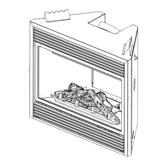
Page 33: Log Placement
LOG PLACEMENT WARNING FAILURE TO POSITION THE LOGS IN ACCORDANCE WITH THESE DIAGRAMS OR FAILURE TO USE ONLY LOGS SPECIFICALLY APPROVED WITH THIS APPLIANCE MAY RESULT IN PROPERTY DAMAGE OR PERSONAL INJURY. LOGS MUST BE PLACED IN THEIR EXACT LOCATION IN THE APPLIANCE. DO NOT MODIFY THE PROPER LOG POSITIONS, SINCE APPLIANCE MAY NOT FUNCTION PROPERLY AND DELAYED IGNITION MAY OCCUR. -
Page 34: Glowing Embers
GLOWING EMBERS Tear the glowing embers into pieces and place along the front row of ports covering all of the burner area in front of GLOWING EMBERS the small logs. Care should be taken to shred the embers into thin, small irregular pieces as only the exposed edges of the fi... -
Page 35: Optional Blower Installation
7.0 OPTIONAL BLOWER INSTALLATION WARNING RISK OF FIRE AND ELECTRICAL SHOCK. TURN OFF THE GAS AND ELECTRICAL POWER BEFORE SERVICING THIS APPLIANCE. USE ONLY WOLF STEEL APPROVED OPTIONAL ACCESSORIES AND REPLACEMENT PARTS WITH THIS APPLIANCE. USING NON-LISTED ACCESSORIES (BLOWERS, DOORS, LOUVRES, TRIMS, GAS COMPONENTS, VENTING COMPONENTS, ETC.) COULD RESULT IN A SAFETY HAZARD AND WILL VOID THE WARRANTY AND CERTIFICATION. -
Page 36: Operation
8.0 OPERATION WARNING IF YOU DO NOT FOLLOW THESE INSTRUCTIONS EXACTLY, A FIRE OR EXPLOSION MAY RESULT CAUSING PROPERTY DAMAGE, PERSONAL INJURY OR LOSS OF LIFE. ALWAYS LIGHT THE PILOT WHETHER FOR THE FIRST TIME OR IF THE GAS SUPPLY HAS RUN OUT WITH THE GLASS DOOR OPENED OR REMOVED. -
Page 37: Adjustments
9.0 ADJUSTMENTS PILOT BURNER ADJUSTMENT Adjust the pilot screw to provide properly sized fl ame. Turn in a clockwise PILOT direction to reduce the gas fl ow. BURNER THERMOPILE Inlet pressure can be checked by turning screw (A) THERMOCOUPLE counter-clockwise until loosened and then placing pressure gauge tubing over the test point. -
Page 38: Flame Characteristics
FLAME CHARACTERISTICS It’s important to periodically perform a visual check of the pilot and burner fl ames. Compare them to the illustrations provided. If any fl ames 3/8” - 1/2” appear abnormal call a service person. FLAME MUST ENVELOP UPPER 3/8"... -
Page 39: Care Of Glass
10.1 CARE OF GLASS WARNING DO NOT CLEAN GLASS WHEN HOT! DO NOT USE ABRASIVE CLEANERS TO CLEAN GLASS. HOT GLASS WILL Buff lightly with a clean dry soft cloth. Clean both sides CAUSE BURNS. of the glass after the fi rst 10 hours of operation with a DO NOT TOUCH GLASS recommended fi... -
Page 40: Replacements
11.0 REPLACEMENTS WARNING FAILURE TO POSITION THE PARTS IN ACCORDANCE WITH THIS MANUAL OR FAILURE TO USE ONLY PARTS SPECIFICALLY APPROVED WITH THIS APPLIANCE MAY RESULT IN PROPERTY DAMAGE OR PERSONAL INJURY. ** THIS IS A FAST ACTING THERMOCOUPLE. IT IS AN INTEGRAL SAFETY COMPONENT. REPLACE ONLY WITH A FAST ACTING THERMOCOUPLE SUPPLIED BY WOLF STEEL LTD. - Page 41 FLEXIBLE VENT KITS REF NO. PART NO. DESCRIPTION GD420 (5 FT) W010-0772 5" FLEXIBLE VENT PIPE - (5 FT) C/W SPACERS W730-0012 8" FLEXIBLE VENT PIPE - (5 FT) GD430 (10 FT) W730-0013 8" FLEXIBLE VENT PIPE - (10 FT) W010-0773 5"...
- Page 42 ACCESSORIES REF NO. PART NO. DESCRIPTION GD36 THERMOSTATIC SENSOR CONTROL KIT - FOR USE WITH GD65 ONLY W500-0033 VARIABLE SPEED SWITCH WALL MOUNTING PLATE KB35 VARIABLE SPEED SWITCH GA-566 HOT AIR DISTRIBUTION KIT W690-0005 THERMOSTAT - 110V - FOR USE WITH GA-566 ONLY GA-70 EXTENSION KIT - 5FT GA-72...
-
Page 43: Troubleshooting
12.0 TROUBLESHOOTING WARNING ALWAYS LIGHT THE PILOT WHETHER FOR THE FIRST TIME OR IF THE GAS SUPPLY HAS RAN OUT, WITH THE GLASS DOOR OPEN OR REMOVED. TURN OFF THE GAS AND ELECTRICAL POWER BEFORE SERVICING THE APPLIANCE. APPLIANCE MAY BE HOT, DO NOT SERVICE UNTIL APPLIANCE HAS COOLED. DO NOT USE ABRASIVE CLEANERS. - Page 44 SYMPTOM PROBLEM TEST SOLUTION Pilot will not light. No spark at pilot burner. Check if pilot can be lit by a match. Check that the wire is connected to the push button igniter. Check if the push button igniter needs tightening. Replace the wire if the wire insulation is broken or frayed.
- Page 45 SYMPTOM PROBLEM TEST SOLUTION White / grey fi lm forms. Sulphur from fuel is being Clean the glass with a recommended gas appliance deposited on glass, logs or glass cleaner. combustion chamber surfaces. DO NOT CLEAN GLASS WHEN HOT. If deposits are not cleaned off regularly, the glass may become permanently marked.
-
Page 46: Warranty
13.0 WARRANTY CONTINENTAL® products are manufactured under the strict Standard of the world recognized ISO 9001 : 2008 Quality Assurance Certifi cate. CONTINENTAL® products are designed with superior components and materials assembled by trained craftsmen who take great pride in their work. The burner and valve assembly are leak and test-fi red at a quality test station. The complete appliance is again thoroughly inspected by a qualifi... -
Page 47: Service History
14.0 SERVICE HISTORY 43.1 W415-0778 / D / 09.13.12... - Page 48 W415-0778 / D / 09.13.12...
Need help?
Do you have a question about the BCDV42N and is the answer not in the manual?
Questions and answers