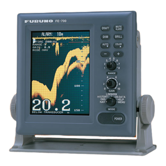
Furuno FE-700 Installation Manual
Navigational echo sounder
Hide thumbs
Also See for FE-700:
- Installation manual (61 pages) ,
- Service manual (58 pages) ,
- Operator's manual (44 pages)
Table of Contents
Advertisement
NAVIGATIONAL ECHO SOUNDER
SAFETY INSTRUCTIONS .............................................................................i
EQUIPMENT LISTS ......................................................................................ii
SYSTEM CONFIGURATION .......................................................................iv
1. MOUNTING ...............................................................................................1
1.1 Category of Equipment .......................................................................................................1
1.2 Display Unit.........................................................................................................................1
1.3 Transducer..........................................................................................................................4
1.4 Distribution Box...................................................................................................................6
1.5 Matching Box ......................................................................................................................7
1.6 Digital Depth Indicator (option) FE-720 ...............................................................................7
1.7 Transducer Switch Box (option) EX-8..................................................................................8
1.8 Gate Valve (option) GV-50B, GV-200B-8B ..........................................................................9
2. WIRING ................................................................................................... 11
3. CHANGING POWER SPECIFICATIONS ...............................................19
4. ADJUSTMENTS......................................................................................21
4.1 Transducer Setting............................................................................................................21
4.2 Setting the Time ................................................................................................................22
PACKING LISTS........................................................................A-1
OUTLINE DRAWINGS.................................................................D-1
INTERCONNECTION DIAGRAMS.................................................S-1
Installation Manual
www.furuno.co.jp
FE-700
Advertisement
Table of Contents

Related Manuals for Furuno FE-700


Summary of Contents for Furuno FE-700
-
Page 1: Table Of Contents
Installation Manual NAVIGATIONAL ECHO SOUNDER FE-700 SAFETY INSTRUCTIONS ................i EQUIPMENT LISTS ..................ii SYSTEM CONFIGURATION ...............iv 1. MOUNTING ....................1 1.1 Category of Equipment .......................1 1.2 Display Unit.........................1 1.3 Transducer..........................4 1.4 Distribution Box........................6 1.5 Matching Box ........................7 1.6 Digital Depth Indicator (option) FE-720 ................7 1.7 Transducer Switch Box (option) EX-8..................8... - Page 2 : +81-(0)798-65-4200 A : JAN 2000 Printed in Japan All rights reserved. P9 : AUG . 23, 2007 Pub. No. IME-23660-P9 *00080891010* *00080891010* (TATA ) FE-700 *00080891010* *00080891010* * 0 0 0 8 0 8 9 1 0 1 0 *...
-
Page 3: Safety Instructions
FURUNO will assume no responsibility for Do not paint the cable. any damage associated with improper installation. The sheath of the transducer cable is... -
Page 4: Equipment Lists
EQUIPMENT LISTS Standard Supply Name Type Code no. Remarks w/Installation Materials CP02-06400 (000-015-872) Display Unit FE-701 and Accessories FP02-04800 (000-015-469) Distribution Box FE-702 MB-502 000-013-602 For 50B-6B Matching Box MB-504 000-013-604 For 200B-8B 50B-6B w/15 m or 30 m cable Transducer 200B-8B w/15 m, 30 m or 50 m cable... - Page 5 100 VAC-120 VAC, MF-22L-1-100V 000-069-401 Flush mount type 200 VAC-240 VAC, MF-22L-1-200V 000-069-403 Flush mount type Dimmer 100 VAC-120 VAC, MF-22L-2-100V 000-069-402 Bulk head type 200 VAC-240 VAC, MF-22L-2-200V 000-069-404 Bulk head type With Installation Materials Terminal Box DS-802 000-029-064 1 set CP65-00903 (000-029-064) EGC Printer...
-
Page 6: System Configuration
SYSTEM CONFIGURATION DISPLAY UNIT FE-701 Terminal Box DS-802 IEC 61162-1 DIGITAL DEPTH INDICATOR FE-720 IEC 61162-1 Navigation Device DISTRIBUTION IEC 61162-1 Navigation Device FE-702 EIA-232C Personal Computer Printer DIMMER CONTACT CLOSURE Alarm Unit Ship's mains 100-115 VAC/200-230 VAC or 24 VDC TRANSDUCER SWITCH BOX EX-8 JUNCTION BOX... -
Page 7: Mounting
1. MOUNTING NOTICE Do not apply paint, anti-corrosive sealant or contact spray to coating or plastic parts of the equipment. Those items contain organic solvents that can damage coating and plastic parts, especially plastic connectors. 1.1 Category of Equipment Equipment for protected area •... - Page 8 • Mount the unit where shock and vibration are minimal. • Keep the unit away from electromagnetic field-generating equipment such as motors and generators. • For maintenance and checking purposes, leave sufficient space at the sides and rear of the unit and leave slack in cables.
- Page 9 Dummy cover 5x20 tapping screws 1.2.4 Flush mounting There are two types of flush mount kits, F type and S type. For details, see the outline diagrams at the back of this manual.
-
Page 10: Transducer
F type Flush Mount Kit (F): OP02-79-1 (001-229-290) OP02-79-2 (001-229-300) OP02-79-3 (001-229-310) No. Name Type Code no. Remarks 100-279-270 OP02-79-1:N3.0 Cosmetic panel 02-129-1041-0 100-279-280 OP02-79-2:2.5GY5/1.5 100-279-290 OP02-79-3:7.5GY7/2 Hex bolt M6x12 000-162-897-10 Spring washer 000-158-855-10 Prepare a cutout in the mounting location whose dimensions are 210 (W) x 194 (H) mm. Attach the cosmetic panel (02-129-1041-0) to the display unit with four hex bolts (M6x12) and four spring washers (M6). -
Page 11: Mounting Location
1.3.1 Mounting Location To decide the location of the transducer, the following points should be taken into account. • The most important matter is where the transducer is installed. The position should be free from aeration possibly occurring beneath the hull and also not affected by engine and propeller noise. -
Page 12: Distribution Box
7. It is recommended to enclose the transducer cable in a conduit pipe for waterproofness and electrical shielding as well as for protecting the cable from mechanical damage. The conduit pipe should be fixed to the flange on the transducer tank. The pipe should be of such a length to clear the water level when the ship is fully loaded. -
Page 13: Matching Box
1.5 Matching Box The matching box should be selected depending on the transducer type; • 50B-6B transducer: MB-502 • 200B-8B transducer: MB-504 Fasten the matching box with four Trapping screws (6x20: local supply). Compass safe distances are as follows; standard compass: 0.50 m, Steering compass: 0.40 m. 1.6 Digital Depth Indicator (option) FE-720 The indicator can be installed on a tabletop, on the overhead. -
Page 14: Transducer Switch Box (Option) Ex-8
F type Use the accessories FP65-00401 (See page A-7). 1. Prepare a cutout in the mounting location whose dimensions are 183 (W) x 92 (H) mm. 2. Attach the cosmetic panel (20-016-1051) to the indicator with Two hex bolts (M6x12) and two spring washers (M6). -
Page 15: Gate Valve (Option) Gv-50B, Gv-200B-8B
1.8 Gate Valve (option) GV-50B-6B, GV-200B-8B Assemble the Gate Valve as shown below. Refer to the drawing at the end of this manual. 1. Disassemble the gate valve assembled tentatively: spacer, gasket1, gate valve, gasket 2, O-ring (P170), seachest cap and shaft assembly. When assembling the gate valve, use original washers, bolts and nuts. - Page 16 8. Grease O-ring (P170) and seachest cap lightly, and attach O-ring (P170) and gasket 2 to the bottom of seachest cap. O-ring (P170) and gasket 2 are attached by adhesion of grease. 9. Place the assembly made at step 8 on the gate valve. 10.
-
Page 17: Wiring
2. WIRING Wiring Connect three cable assemblies (supplied) between the display unit and distribution box. Display unit FE-701 (rear panel) FM-C6FPS002-100 MJ-A3SPF0015-100C POWER Digital depth indicator FE-720 (option) DATA When silencing the alarm beep, connect 2.0 sq to *2 connector. Personal computer TTYCYS-4 MJ-A10SPF0002-100... - Page 18 When the Transducer Switch Box EX-8 is used, the interconnection diagram is as follows. Display unit FE-701 (rear panel) MJ-A3SPF0015-100C FM-C6FPS003-020 POWER Digital depth indicator FE-720 (option) DATA When silencing the alarm beep, connect 2.0 sq to *2 connector. Personal computer TTYCYS-4 (EIA-232C) MJ-A10SPF0002-100...
- Page 19 Cable Fabrication of DPYCYS-2.5, DPYCYS-1.5, MJ-A3SPF0015-100C , FM-C6FPS0002-100 and TPYCYS-1.5 Fabricate the power and other cables as illustrated below to connect them to the Distribution box. Vinyl Sheath Cores Shield 40mm 50mm Armor 100mm Fold back shield over on vinyl sheath. Vinyl Sheath Cores Shield...
- Page 20 Several cables are required to supply at local. In this manual, JIS (Japan Industrial Standard ) cables are specified. Use equipment cables refering to the figures below. Shield Sheath Shield Sheath Armor Armor Core Core S=1.5 mm S=2.5 mm =1.56mm Vinyl sheath =2.01mm Vinyl sheath...
- Page 21 Cable Fabrication of TTYCYS-4 TTYCYS is a Japan Industrial Standard (JIS) cable. Use the equipment one. Vinyl Sheath Shield Cores 40mm 50mm Armor 100mm Fold back shield over on vinyl sheath. Vinyl Sheath Shield Taping Armor Vinyl Tape Vinyl Sheath Shield 3 mm Clamp here.
- Page 22 Power Supply Cable from Ship's Mains If the ship's mains is AC, the power supply cable must be connected to TB5 in the Distribution Box. In case of DC ship's mains, cable must be connected to TB6 in the Distribution Box. For further information, refer to page 16.
- Page 23 Alarm system connection The power error and shallow water alarms, which produce audio and visual alarms in the event of power failure and shallow water, can be output by connecting the distribution box to the ship’s alarm system. Connect the DPYCYS-1.5 cable between TB1 in the Distribution Box and the alarm system of the ship referring to the schematic diagram at the end of this manual.
- Page 24 Case2: Silencing the alarm from the digital depth indicator FE-720 When the main display unit FE-701 activates an alarm, it can be deactivated at the FE-701 itself and also, it can be deactivated from the digital depth indicator FE-720. To do this, connect as follows.
-
Page 25: Changing Power Specifications
3. CHANGING POWER SPECIFICATIONS This unit is set at factory to operate from 200-230 VAC ship's mains. For connection to a 100-115 VAC or 24 VDC ship's mains, modification of the power section is necessary. Note: Tick the appropriate box on the inside of the distribution box cover to denote the power use. - Page 26 24 VDC Ship's Mains Remove the cover of the distribution box. Remove P3 connector from J4 on the CONE Board. Reattach P3 connector to J3 on the CONE Board. Connect the power cable to TB6. CONE Board For DC ship's mains For AC ship's mains Distribution box, inside view...
-
Page 27: Adjustments
4. ADJUSTMENTS This section provides the procedures for initial set up of the equipment. The type of transducer used should be properly set before operating the equipment. Transducer Setting Select the type of transducer used as follows. 1. Press the POWER Switch while pressing any key. Release the key when the following display appears EXTENSION MODE TRANSDUCER SETTING... -
Page 28: Setting The Time
Setting the Time Open the system menu 2 referring to the operator’s manual. SYSTEM MENU 2 MENU SELECT 1 2 3 TIME ADJST INTERNAL EXTERNAL MONTH YEAR 2001 (∼2100) HOUR (0∼23) MINUTE (0∼59) SECOND (0∼59) 01 JAN 2001 00:00:00 ▼▲: To select item - +: To set option Select other mode to exit. - Page 38 D-3a...
- Page 48 D-13 Y. Hatai...
- Page 49 D-14 Y. Hatai...
- Page 50 D-15 Y. Hatai...
- Page 51 D-16 Takahashi.T...
- Page 52 D-17 Y. Hatai...
- Page 53 D-18 Y. Hatai...
- Page 54 D-19 T.MAtsuguchi Apr.28'06...
- Page 55 D-20 T.Matsuguchi Apr.28'06...
-
Page 56: Interconnection Diagrams
2台の送受波器を装備するときは切換器を使用すること。 *6)接続の詳細はFE-720相互結線図を参照のこと。 USE A SWITCH BOX EX-8 WHEN TWO TRANSDUCERS ARE INSTALLED. NOTE *1. SHIPYARD SUPPLY. DRAWN TITLE *2. OPTION. FE-700 T.YAMASAKI Apr. 19 '07 *3. FITTED AT FACTORY. CHECKED 名称 音響測深機 T.TAKENO *4. CABLE LENGTH BETWEEN DISTRIBUTION BOX AND MATCHING BOX IS WITHIN 400 m.