
Related Manuals for York ACTIVA 100


Summary of Contents for York ACTIVA 100
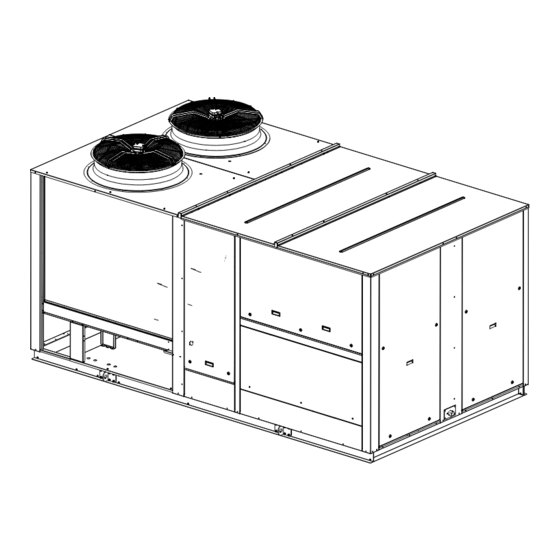
- Page 1 ACTIVA SERIES ROOF TOP Air Conditioners 100/175 Installation manual Ref.: N-40428_EN 0413...
-
Page 2: Table Of Contents
Index Index Installation manual........................1 Safety instructions........................2 Icons used in this document.....................2 Instructions for storage, transport and handling of the unit............3 1.3.1 Disposal of packaging......................3 1.3.2 Hoisting points..........................4 1.3.3 Centre of gravity........................5 Technical data..........................6 1.4.1 ARC technical and physical data (Only cooling)..............6 1.4.2 ARH technical and physical data (Heat pump).................7 1.4.3... - Page 3 Index 1.13 Instructions for starting up the unit..................32 1.13.1 Electrical checks........................32 1.14 Unblocking the unit safely in case of breakdown..............33 1.15 Regular maintenance tasks performed by specialised personnel..........33 1.15.1 Planned Maintenance Schedule.....................34 1.15.2 Maintenance tasks performed by specialised personnel............34 Options and accessories......................37 DPC-1 Programmable digital thermostat with communication..........39 2.1.1...
-
Page 4: Installation Manual
Installation manual... -
Page 5: Safety Instructions
Installation manual Safety instructions 1.1 Safety instructions This document contains the necessary information for the safe and efficient transportation, assembly and installation of the air conditioning unit. This guarantees the condition of the unit and its operating safety. Only an authorised company may assemble the air conditioning unit. A T T E N T I O N Only authorised companies with the appropriate technical resources and suitably trained personnel may install the air conditioning unit. -
Page 6: Instructions For Storage, Transport And Handling Of The Unit
Installation manual Instructions for storage, transport and handling of the unit 1.3 Instructions for storage, transport and handling of the unit Delivery inspection The unit should be carefully inspected for visible damage or abnormalities as soon as it is received. Any abnormalities or damage to the unit should be communicated to both the transportation and insurance company in writing. -
Page 7: Hoisting Points
Installation manual Instructions for storage, transport and handling of the unit 1.3.2 Hoisting points The points designed for hoisting the unit are located on the beams on its base -arrows-. Install 5/8" shackles -A- on the points designed for hoisting. A T T E N T I O N Do not use fork lifts in operations to load and unload the unit. -
Page 8: Centre Of Gravity
Installation manual Instructions for storage, transport and handling of the unit 1.3.3 Centre of gravity Models 100 / 125 1185 1760 150 / 175 1160 2380 All measurements in mm. 1. End of the outdoor coils 2. Approximate centre of gravity... -
Page 9: Technical Data
Installation manual Technical data 1.4 Technical data 1.4.1 ARC technical and physical data (Only cooling) ARC/ARG models Net cooling capacity Cooling capacity (1) Rated absorbed power Net EER 3,46 3,21 3,13 2,91 Heating Optional heating element heating capacity (400 V) (2) 37 ‑... -
Page 10: Arh Technical And Physical Data (Heat Pump)
Installation manual Technical data 1.4.2 ARH technical and physical data (Heat pump) ARH/ARD models Net cooling capacity Cooling capacity (1) Rated absorbed power Net EER 3,46 3,21 3,13 2,91 Net heating capacity Rated absorbed power Heat capacity (1) Net COP 3,48 3,44 3,20... -
Page 11: Unit Sound Pressure Data
Installation manual Technical data 1.4.3 Unit sound pressure data Octave band sound spectrum dB(A), outdoor Models 125 Hz 87,3 90,1 250 Hz 85,4 86,6 500 Hz 84,5 84,2 1000 Hz 84,9 2000 Hz 79,7 4000 Hz 73,4 75,5 8000 Hz 68,4 73,2 Sound power level dB (A) -
Page 12: Arc / Arh Units With Auxiliary Heating Element
Installation manual ARC / ARH units with auxiliary heating element 1.5 ARC / ARH units with auxiliary heating element The power supply to the heating resistor must be independent to the general power supply to the unit and must be fitted with its own circuit breaker according to the table: Heating element Power Maximum circuit breaker... -
Page 13: Measurements, Clearances And Accesses
Installation manual Measurements, clearances and accesses 1.7 Measurements, clearances and accesses 1.7.1 Dimensions of the duct connections Models 100 / 175, side ducts (horizontal) N O T E Floor plan without the top panel Lateral supply Lateral return Model ARC / 100 / 125 1380 1720... - Page 14 Installation manual Measurements, clearances and accesses Models 100 / 175, lower ducts (vertical) N O T E Floor plan without the top panel Bottom supply Lower return Model ARC / 100 / 125 1465 1755 150 / 175 1690 2205...
-
Page 15: Connections For Supply And Return Ducts
Installation manual Measurements, clearances and accesses 1.7.2 Connections for supply and return ducts Units are shipped with the openings for the connection of the return duct covered. For applications with downward discharge ducts 1. The return compartment is accessed by removing the access panel -B2-. -
Page 16: General Measurements And Accesses
Installation manual Measurements, clearances and accesses 1.7.3 General measurements and accesses Minimum clearance above the unit The unit is designed to be installed outdoors. In ground level installations, the building eaves must not be at a vertical distance of less than 3000 mm from the top of the unit. - Page 17 Installation manual Measurements, clearances and accesses Models ARC/ARH ‑ 100 / 175 Model 100 / 125 4036 1957 1123 2300 150 / 175 5085 2557 1473 2750 A1. Access to indoor fan A2. Access to electrical box A3. Access to return/economiser/filters A4.
-
Page 18: Arc Output
Installation manual ARC output 1.8 ARC output 1.8.1 ARC ‑ 100 cooling capacities Return air Outdoor coil air temperature (TS) 27 °C 35 °C 46 °C Sensible power kW Sensible power kW Sensible power kW Flow rate °C TS inlet temp. in indoor coil TS inlet temp. -
Page 19: Arc - 150 Cooling Capacities
Installation manual ARC output 1.8.3 ARC ‑ 150 cooling capacities Return air Outdoor coil air temperature (TS) 27 °C 35 °C 46 °C Sensible power kW Sensible power kW Sensible power kW Flow rate °C TS inlet temp. in indoor coil TS inlet temp. -
Page 20: Arh Output
Installation manual ARH output 1.9 ARH output 1.9.1 ARH ‑ 100 cooling capacities Return air Outdoor coil air temperature (TS) 27 °C 35 °C 46 °C Sensible power kW Sensible power kW Sensible power kW Flow rate °C TS inlet temp. in indoor coil TS inlet temp. -
Page 21: Arh - 150 Cooling Capacities
Installation manual ARH output 1.9.3 ARH ‑ 150 cooling capacities Return air Outdoor coil air temperature (TS) 27 °C 35 °C 46 °C Sensible power kW Sensible power kW Sensible power kW Flow rate °C TS inlet temp. in indoor coil TS inlet temp. -
Page 22: Arh - 100 Thermodynamic Heating Capacities
Installation manual ARH output 1.9.5 ARH ‑ 100 thermodynamic heating capacities Outdoor air temperature TS °C Return Flow rate air TS °C 20,1 20,9 21,9 22,3 23,4 24,2 26,0 26,9 21,8 22,7 23,7 24,2 25,3 26,2 28,1 29,1 (Minimum) 22,3 23,2 24,2 24,7... -
Page 23: Arh - 150 Thermodynamic Heating Capacities
Installation manual ARH output 1.9.7 ARH ‑ 150 thermodynamic heating capacities Outdoor air temperature TS °C Return Flow rate air TS °C 28,9 30,1 31,4 32,1 33,6 34,8 37,3 38,7 31,3 32,6 34,0 34,8 36,4 37,7 40,4 41,9 (Minimum) 32,0 33,3 34,8 35,5... -
Page 24: Indoor Fan
Installation manual Indoor fan 1.10 1.10 Indoor fan Centrifugal fan with forward-curved blades. • 100/125 models: A double-turbine fan with a shared shaft, driven by a single motor. • 150/175 models: Two independent fans, each with their motor. Both cases have BX-type pulley and belt transmission. The motor pulley has a diameter that can be adjusted in ½-turn intervals. - Page 25 Installation manual 1.10 Indoor fan ARC / ARH-100, standard drive Flow rate Motor pulley opening adjustment (no. of turns) 16000 17000 18000 19000 20000 21000 22000 ASP = Available static pressure. ARC / ARH-100, HPD optional drive Flow rate Motor pulley opening adjustment (no. of turns) 16000 17000 18000...
- Page 26 Installation manual Indoor fan 1.10 ARC / ARH-125 standard drive Flow rate Motor pulley opening adjustment (no. of turns) 18000 19000 20000 21000 22000 23000 24000 25000 ASP = Available static pressure. ARC / ARH-125 HPD optional drive Flow rate Motor pulley opening adjustment (no.
- Page 27 Installation manual 1.10 Indoor fan ARC / ARH-150 standard drive Flow rate Motor pulley opening adjustment (no. of turns) 22000 23000 24000 25000 26000 27000 28000 29000 30000 31000 32000 ASP = Available static pressure.
- Page 28 Installation manual Indoor fan 1.10 ARC / ARH-150 HPD optional drive Flow rate Motor pulley opening adjustment (no. of turns) 22000 23000 24000 25000 26000 27000 28000 29000 30000 31000 32000 ASP = Available static pressure.
- Page 29 Installation manual 1.10 Indoor fan ARC / ARH-175 standard drive Flow rate Motor pulley opening adjustment (no. of turns) 25000 26000 27000 28000 29000 30000 31000 32000 33000 34000 35000 ASP = Available static pressure.
-
Page 30: Pressure Drop In Options/Accessories
Installation manual Pressure drop in options/accessories 1.11 ARC / ARH-175 HPD optional drive Flow rate Motor pulley opening adjustment (no. of turns) 25000 26000 27000 28000 29000 30000 31000 32000 33000 34000 35000 ASP = Available static pressure. 1.11 Pressure drop in options/accessories Pressure drop (Pa) Model 100 / 125... -
Page 31: Characteristics Of The Facility Where The Unit Will Be Installed
Installation manual 1.12 Instructions for installation and connection of the unit If possible, in warm zones like the southern Europe, the unit should be located on the north or east side of the building or property. The location chosen for the unit must provide the condenser with an unlimited air supply. As well as the technical data given in this document and any others that are applicable, please bear in mind that the unit has been designed for outdoors installation only. -
Page 32: Specifications For The Foundation Or Anchoring Of The Unit
Installation manual Instructions for installation and connection of the unit 1.12 1.12.3 Specifications for the foundation or anchoring of the unit Where the unit is to be installed at ground level, the characteristics of the ground it will sit on must be taken into account. - Page 33 Installation manual 1.12 Instructions for installation and connection of the unit To install the power cable, loosen the closures -1- by 1/4 turn and remove the electrical board panel. Bringing the power and control cables through the side of the unit. Remove the lower panel -4- The side panel of the electrical box has PG48 packing glands -5- for the power cable and PG21 packing...
- Page 34 Installation manual Instructions for installation and connection of the unit 1.12 CONTROL LINE Connect the cable to the terminals indicated and firmly tighten the securing bolts. Also consult the Wiring Diagrams. N O T E The complete wiring diagram for the unit is attached to the inside of the electrical panel.
-
Page 35: Instructions For Starting Up The Unit
Installation manual 1.13 Instructions for starting up the unit Apply a moderate amount of sealing paste to the threads of the male part of the joint. The drain line must have a siphon in order to facilitate proper drainage. If it is not a siphon made of flexible material, it is recommended that it has a stopper -1- for its drainage and cleaning. -
Page 36: Unblocking The Unit Safely In Case Of Breakdown
Installation manual Unblocking the unit safely in case of breakdown 1.14 Rotating direction of the Scroll compressors The scroll compressors and the fans only operate correctly if they rotate in the correct direction. All of the motors and compressors in the unit are connected so that they rotate correctly. If the compressors are not connected correctly and are rotating in the wrong direction: •... -
Page 37: Planned Maintenance Schedule
Installation manual 1.15 Regular maintenance tasks performed by specialised personnel 1.15.1 Planned Maintenance Schedule The following table shows the recommended frequency for regular maintenance tasks. Depending on the environmental and working conditions where the unit is installed, maintenance tasks may be carried out more or less frequently. -
Page 38: Indoor Coil
Installation manual Regular maintenance tasks performed by specialised personnel 1.15 2. Belt tightening: a. Tighten the belts by turning the tensor screw -1-. b. Measure the tightness of the belts. In the event that you do not have a tension gauge, use the following practical method: •... - Page 39 Installation manual 1.15 Regular maintenance tasks performed by specialised personnel Condensate tray and drain trap Loosen the four bolts -1- and extract away from the tray -2-. Remove all dirt and residue accumulated in the condensate tray. Check that neither the condensation outlet nor the drain trap is blocked.
-
Page 40: Options And Accessories
Options and accessories... - Page 41 Options and accessories An “OPTION” (O) includes those factory-fitted and supplied installed in the unit and ready for use. An “ACCESSORY” (A) is defined as those that are fully or partially fitted on site. A T T E N T I O N The ECONOMISER is considered an “OPTION”, despite the fact that the rain protection must be installed on site for transportation reasons.
-
Page 42: Dpc-1 Programmable Digital Thermostat With Communication
Options and accessories DPC-1 Programmable digital thermostat with communication 2.1 DPC-1 Programmable digital thermostat with communication Interior appearance of the thermostat N O T E With the lid lifted, showing the central panel The lid is only lifted to access the controls. HVAC mode Battery flat Comfort (day) - Page 43 Options and accessories DPC-1 Programmable digital thermostat with communication The HVAC system is switched off in this mode. The screen displays OFF-7-. Cold The screen displays COOL-4-. • Icon -8- flashes if there is demand. • Icon -8- remains static if not. Heat The screen displays HEAT-5-.
- Page 44 Options and accessories DPC-1 Programmable digital thermostat with communication Auto The screen displays AUTO-3-. The heating and the cooling functions of the system are enabled. • Icons -8- and -9- flash if there is demand. • Icons -8- and -9- remain static if not. Programmed The screen displays PROG-2- and AUTO-3-.
-
Page 45: Button Functions
Options and accessories DPC-1 Programmable digital thermostat with communication Ventilation only This is accessed in OFF-7- mode and button -B- is pressed to select the fan speed. This means that the HVAC system is stopped and only the fan is running. 2.1.2 Button functions HVAC mode button -A- Normal mode ) the current HVAC mode will be modified (OFF, COOL, HEAT,... -
Page 46: Economiser, Modulating, Temperature Control
Options and accessories Economiser, modulating, temperature control Programming button -D- Normal mode ) it will enter Programming mode , which enables the selection By pressing this button (in of one of the following options: Occupied , Comfort or Day sta‐ Programming of the set temperatures for heat and cold in tus. -
Page 47: Enthalpy Probes
Options and accessories Enthalpy probes The economiser can be adapted to work as a motorised outdoor air damper and the minimum and maximum outdoor air volume values can be set according to installation requirements (bearing in mind the unit operating limits). Model 100 / 125 1805... -
Page 48: Exhaust Fan
Options and accessories Exhaust fan When the outdoor air inlet opens and the return air flow is closed proportionally, the pressure inside the building increases. When the pressure is greater than atmospheric pressure, the damper is opened to release any excess pressure directly outdoors. Where the return duct connection to the unit is at the bottom, the barometric damper assembly and rain protection are installed on the side of the unit. -
Page 49: Fixed Outdoor Air Damper
Options and accessories Fixed outdoor air damper Up to approximately 30% of outdoor air inlet opening, operating as a barometric damper. The fans are enabled at this point and the air is discharged directly outdoors. Where the return duct connection to the unit is at the bottom, the fans, the barometric damper assembly and rain protection are installed on the side of the unit. -
Page 50: Fire Detection Thermostat
Options and accessories Fire detection thermostat 2.12 2.12 Fire detection thermostat As standard, the unit is fitted with an air supply probe that stops at 80 °C and switches to "lock out" mode, in which case the control must be manually reset. Using this option, a set temperature probe and manual reset are located in the unit supply area. -
Page 51: Roofcurb Mounting Base, Adjustable Type
Options and accessories 2.19 Roofcurb mounting base, adjustable type The roofcurb must be attached to the supporting structure of the building roof. To do so, use the nuts and bolts supplied or use welding. To prevent humidity or condensation from filtering into the building, all of the outer perimeter must be insulated and sealed with an extension of the same material used for the roofing finish. - Page 52 Options and accessories Roofcurb mounting base, adjustable type 2.19 With similar characteristics as the fixed type, but with the advantage of being able to adjust the level of the support surface for the unit to overcome the gradient of the roof. 2120 SOLO EN 150/175...
-
Page 53: Unit Installation Data
Unit installation data... -
Page 54: List Of Tests For Unit Start-Up
Unit installation data List of tests for unit start-up 3.1 List of tests for unit start-up Please complete the following forms to register the full details of the installation and the start-up inspection. Complete the blank fields or mark the appropriate box, as applicable. Company performing installation: Installing technician: Name / project number:... -
Page 55: Start-Up Data
Unit installation data Start-up data 3.2 Start-up data Electrical data Rating Actual plate Power supply Control voltage Fan consumption (A) Consumption of condenser fan 1 (A) Check specifica‐ Consumption of condenser fan 2 (A) tions in the Installa‐ Consumption of compressor 1 (A) tion Manual Consumption of compressor 2 (A) Consumption of supply fan (A) - Page 56 Unit installation data Start-up data OPTIONS Heating mode (hot water coil) Air temperature Capacity: _____ (kW) Temperature (°C) Supply air (at 100 %) Return air Hydraulic circuit Temperature (°C) Pressure (bar) Water inlet Water outlet Others Type or model Outdoor fan 1 Surge protection adjusted Type or model Outdoor fan 2...
-
Page 57: Wiring Diagrams
Wiring diagrams... -
Page 58: Micro Switch Configuration
Wiring diagrams Micro switch configuration 4.1 Micro switch configuration The micro switches are used to establish the following configurations: A T T E N T I O N In order to update the new configuration of the micro switches the power supply has to be shut off MICRO SWITCH CONFIGURATION Number Status... -
Page 59: Fault Table
Wiring diagrams Fault table 4.2 Fault table The red LED on the YKNOpen electronic board is responsible for showing the state of faults on the unit: • When the red LED remains off there are no faults in the unit. •... -
Page 60: Incidents
Wiring diagrams Incidents 4.3 Incidents The green LED on the YKNOpen electronic board is responsible for showing the state of incidents on the unit: • If the green LED flashes in a constant sequence, there are no incidents in the unit. •... -
Page 61: Test Button
Wiring diagrams DPC-1 thermostat 4.3.1 Test button • If the test button is pressed until the green led is activated, certain times are shortened. • If the test button is pressed until the orange led is activated, any fault that has been detected is reset. •... -
Page 62: Arc/Arh 100 - 125 Wiring Diagrams
Wiring diagrams ARC/ARH 100 – 125 wiring diagrams 4.5 ARC/ARH 100 – 125 wiring diagrams (0 0 ) (01) (02) (0 3 ) (0 4 ) (0 5 ) (0 7) (0 9) (14) (13) (21) (14) (18) (22) (23) (15) (17) (25) - Page 63 Wiring diagrams ARC/ARH 100 – 125 wiring diagrams X1/.. 400V 230V 1200 VA (18) (22) (14) (23) X1/.. I-2649a (2/4) ARH: 100 y 125 ARC: 100 y 125 X1/.. HP21 150 VA HP11 (05) (07) (09) X1/.. (03) (09) (01) (04) (05) (07)
-
Page 64: Wiring Diagrams
Wiring diagrams ARC/ARH 100 – 125 wiring diagrams EEV-1 EEV-2 EEVC-1 EEVC-2 SP-1 SP-2 I-2649a (4/4) ARH: 100 y 125 ARC: 100 y 125 White Black Green S1 configuration on A1 board (VCH models) High and low pressure switch 2 Thermostat Outdoor fan motor trip switch 2 Electronic board [A1]... -
Page 65: Arc/Arh 150 - 175 Wiring Diagrams
Wiring diagrams ARC/ARH 150 – 175 wiring diagrams 4.6 ARC/ARH 150 – 175 wiring diagrams (0 0 ) (01) (02) (0 3 ) (0 4 ) (0 5 ) (0 6 ) (0 7 ) (0 8 ) (0 9 ) (1 0 ) (14) (13) - Page 66 Wiring diagrams ARC/ARH 150 – 175 wiring diagrams X1/.. 400V 230V 1200 VA (18) (22) (23) (14) X1/.. I-2650a (2/4) ARH 150 y 175 ARC 150 y 175 X1/.. HP21 250 VA HP11 (05) HP12 HP22 (06) (07) (09) KM10 (08) (010) X1/..
- Page 67 Wiring diagrams ARC/ARH 150 – 175 wiring diagrams EEV-1 EEV-2 EEVC-1 EEVC-2 SP-1 SP-2 I-2650a (4/4) ARH 150 y 175 ARC 150 y 175 White Black Green S1 configuration on A1 board (VCH models) High and low pressure switch 2 Thermostat Outdoor fan motor trip switch 2 Electronic board [A1]...
Need help?
Do you have a question about the ACTIVA 100 and is the answer not in the manual?
Questions and answers