Napoleon BGD36CFNTR Installation And Operating Instructions Manual
Hide thumbs
Also See for BGD36CFNTR:
- Installation and operating instructions manual (136 pages) ,
- Installation and operation manual (120 pages) ,
- Installation and operating instructions manual (44 pages)
Table of Contents
Advertisement
Available languages
Available languages
Quick Links
INSTALLER: LEAVE THIS MANUAL WITH THE APPLIANCE.
CONSUMER: RETAIN THIS MANUAL FOR FUTURE REFERENCE.
NEVER LEAVE CHILDREN OR OTHER AT RISK INDIVIDUALS ALONE WITH THE APPLIANCE
CONFORMS TO AMERICAN NATIONAL STANDARDS: ANSI Z21.50, CERTIFIED TO CANADIAN CSA 2.22 FOR VENTED GAS FIREPLACES.
CERTIFIED FOR CANADA AND UNITED STATES USING ANSI/CSA METHODS.
SAFETY INFORMATION
WARNING
!
If the information in these instructions
are not followed exactly, a fi re or
explosion may result causing property
damage, personal injury or loss of life.
- Do not store or use gasoline or other fl ammable
vapors and liquids in the vicinity of this or any
other appliance.
- WHAT TO DO IF YOU SMELL GAS:
•
Do not try to light any appliance.
•
Do not touch any electrical switch; do not use
any phone in your building.
•
Immediately call your gas supplier from a
neighbour's phone. Follow the gas supplier's
instructions.
•
If you cannot reach your gas supplier, call the
fi re department.
- Installation and service must be performed by a
qualifi ed installer, service agency or the supplier.
This appliance may be installed in an aftermarket,
permanently located, manufactured home (USA
only) or mobile home, where not prohibited by
local codes.
This appliance is only for use with the type of gas
indicated on the rating plate. This appliance is
not convertible for use with other gases, unless a
certifi ed kit is used.
Decorative Product: Not for use as a heating appliance.
Phone (705)721-1212 • Fax (705)722-6031 • www.napoleonfi replaces.com • hearth@napoleonproducts.com
$10.00
INSTALLATION AND
OPERATING INSTRUCTIONS
Wolf Steel Ltd., 24 Napoleon Rd., Barrie, ON, L4M 0G8 Canada /
103 Miller Drive, Crittenden, Kentucky, USA, 41030
BGD36CFNTR &
BGD36CFNTRE
NATURAL GAS MODEL
BGD36CFPTR &
BGD36CFPTRE
PROPANE GAS MODEL
DANGER
!
A barrier designed to reduce the risk of burns from
the hot viewing glass is provided with this appliance
and shall be installed for the protection of children
and other at-risk individuals.
BARRIER
HOT GLASS WILL CAUSE
BURNS.
DO NOT TOUCH GLASS UNTIL
COOLED.
NEVER ALLOW CHILDREN TO
TOUCH GLASS.
1.28F
W415-1345 / B / 10.22.15
EN
FR
PG
65
Advertisement
Chapters
Table of Contents

Related Manuals for Napoleon BGD36CFNTR


Summary of Contents for Napoleon BGD36CFNTR
-
Page 1: Safety Information
BARRIER Wolf Steel Ltd., 24 Napoleon Rd., Barrie, ON, L4M 0G8 Canada / 103 Miller Drive, Crittenden, Kentucky, USA, 41030 Phone (705)721-1212 • Fax (705)722-6031 • www.napoleonfi replaces.com • hearth@napoleonproducts.com $10.00... -
Page 2: Table Of Contents
TABLE OF CONTENTS INSTALLATION OVERVIEW INTRODUCTION DIMENSIONS GENERAL INSTRUCTIONS GENERAL INFORMATION RATING PLATE INFORMATION VENTING VENTING LENGTHS AND COMPONENTS TYPICAL VENT INSTALLATION SPECIAL VENT INSTALLATIONS 3.3.1 PERISCOPE TERMINATION 3.3.2 CORNER TERMINATION MINIMUM AIR TERMINAL LOCATION CLEARANCES VENTING APPLICATION FLOW CHART DEFINITIONS ELBOW VENT LENGTH VALUES TOP EXIT HORIZONTAL TERMINATION... -
Page 3: Installation Overview
1.0 INSTALLATION OVERVIEW See the sections “MINIMUM ENCLOSURE CLEARANCES” for drywall (or other combustible material) See the section “MINIMUM MANTEL AND ENCLOSURE See the section CLEARANCES” “VENTING” and “INSTALLATION” See the section “INSTALLATION - FRAMING” See the section Side “FRAMING” Wall See the section “GLASS FRONT INSTALLATION / REMOVAL”... -
Page 4: Introduction
2.0 INTRODUCTION WARNING • THIS APPLIANCE IS HOT WHEN OPERATED AND CAN CAUSE SEVERE BURNS IF CONTACTED. • ANY CHANGES TO THIS APPLIANCE OR IT’S CONTROLS CAN BE DANGEROUS AND IS PROHIBITED. • Do not operate appliance before reading and understanding operating instructions. Failure to operate appliance according to operating instructions could cause fi... -
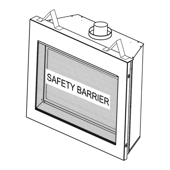
Page 5: Dimensions
DIMENSIONS 5" 127mm 38 1/2" 978mm 7" 34" 27" 686mm 178mm 864mm SAFETY BARRIER 8" 4" 24 1/4" 203mm 102mm 616mm GAS INLET 3" 76.2mm 40" 1016mm 15" 381mm 17" 432mm W415-1345 / B / 10.22.15... -
Page 6: En 2.3 General Instructions
GENERAL INSTRUCTIONS WARNING ALWAYS LIGHT THE PILOT WHETHER FOR THE FIRST TIME OR IF THE GAS SUPPLY HAS RUN OUT, WITH THE GLASS DOOR OPENED OR REMOVED. PROVIDE ADEQUATE CLEARANCE FOR SERVICING AND OPERATING THE APPLIANCE. PROVIDE ADEQUATE VENTILATION. NEVER OBSTRUCT THE FRONT OPENING OF THE APPLIANCE. OBJECTS PLACED IN FRONT OF THE APPLIANCE MUST BE KEPT A MINIMUM OF 48”... -
Page 7: General Information
GENERAL INFORMATION FOR YOUR SATISFACTION, THIS APPLIANCE HAS BEEN TEST-FIRED TO ASSURE ITS OPERATION AND QUALITY! RATES AND EFFICIENCIES Altitude (FT) 0-4,500 0-4500 Max. Input (BTU/HR) 17,000 17,000 Max. Output Steady State (BTU/HR) 10,900 10,900 Effi ciency (w/the fan on) A.F.U.E. -
Page 8: Rating Plate Information
VENT BOTTOM / EVENT INFERIEUR T INFERIEUR T INFERIEUR 1" L'APPAREIL DOIT EVACUER SES GAZ EN UTILISANT L'ENSEMBLE D'EVACUATION PROPRE A NAPOLEON. MANTEL / MANTEAU 12" * REFERER AU MANUEL D'INSTALLATION DE PROPRIETAIRE POUR L'EVACUATION PRECISE. IL EST IMPORTANT * MAXIMUM HORIZONTAL EXTENSION / L'EXTENSION HORIZONTALE MAXIMALE: 2". SEE INSTRUCTION ORIZONTALE MAXIMALE: 2". -
Page 9: Venting
3.0 VENTING WARNING RISK OF FIRE, MAINTAIN SPECIFIED AIR SPACE CLEARANCES TO VENT PIPE AND APPLIANCE. IF VENTING IS INCLUDED WITH SPACERS THE VENT SYSTEM MUST BE SUPPORTED EVERY 3FT (0.9m) FOR BOTH VERTICAL AND HORIZONTAL RUNS. USE SUPPORTS OR EQUIVALENT NON-COMBUSTIBLE STRAPPING TO MAINTAIN THE REQUIRED CLEARANCE FROM COMBUSTIBLES. -
Page 10: Venting Lengths And Components
VENTING LENGTHS AND COMPONENTS Use only Wolf Steel, Simpson Dura-Vent, Selkirk Direct Temp, American Metal Amerivent or Metal-Fab venting components. Minimum and maximum vent lengths, for both horizontal and vertical installations, and air terminal locations for either system are set out in this manual and must be adhered to. For Simpson Dura-Vent, Selkirk Direct Temp, American Metal Amerivent and Metal-Fab follow the installation procedure provided with the venting components. -
Page 11: Typical Vent Installation
TYPICAL VENT INSTALLATION 16" (406MM) 16" (406MM) MINIMUM MINIMUM 40 FT (12M) 40 FT (12M) MAXIMUM MAXIMUM 3 FT (1M) 3 FT (1M) MINIMUM MINIMUM 33" 24 1/4" (838MM) (616MM) REAR VENT TOP VENT W415-1345 / B / 10.22.15... - Page 12 24" (610MM) MAXIMUM BGD36 10" (254MM) 20" (508MM) MINIMUM MAXIMUM 42 3/8" (1076MM) MINIMUM 32 3/8" PLUS RISE* 24 1/4" (822MM) (616MM) MINIMUM PLUS RISE* * See "VENTING" section W415-1345 / B / 10.22.15...
-
Page 13: Special Vent Installations
SPECIAL VENT INSTALLATIONS 3.3.1 PERISCOPE TERMINATION Use the periscope kit to locate the air termination above grade. The periscope must be installed so that when fi nal grading is completed, the bottom air slot is located a minimum 12” (304.8mm) above grade. The maximum allowable vent length is 10’... -
Page 14: Minimum Air Terminal Location Clearances
MINIMUM AIR TERMINAL LOCATION CLEARANCES COVERED BALCONY APPLICATIONS ††* = 3 feet = 2 x ACTUAL (0.9m) (4.6m) INSTALLATIONS CANADA U.S.A. 12” (305mm) 12” (305mm) Clearance above grade, veranda porch, deck or balcony. 9” 12” (305mm) Clearance to windows or doors that open. Δ... -
Page 15: Venting Application Flow Chart
VENTING APPLICATION FLOW CHART TOP EXIT Horizontal Termination Vertical Termination Vertical rise is equal Vertical rise is equal Vertical rise is less Vertical rise is less to or greater than to or greater than than horizontal run than horizontal run the horizontal run the horizontal run Horizontal run +... -
Page 16: Definitions
DEFINITIONS For the following symbols used in the venting calculations and examples are: > - greater than > - equal to or greater than < - less than < - equal to or less than - total of both horizontal vent lengths (Hr) and offsets (Ho) in feet - combined horizontal vent lengths in feet - offset factor: .03 (total degrees of offset - 90°*) in feet - combined vertical vent lengths in feet... -
Page 17: Top Exit Horizontal Termination
TOP EXIT HORIZONTAL TERMINATION ) < (V See graph to determine the required vertical Simple venting confi guration (only one 90° elbow) rise V for the required horizontal run H 40 (12.2) 39 (11.9) REQUIRED 30 (9.1) VERTICAL RISE IN FEET 20 (6.1) (METERS)V 10 (3.1) - Page 18 ) > (V Simple venting configuration See graph to determine the required vertical rise V for the required horizontal run H (only one 90° elbow) 150 (3810) 147 (3733.8) REQUIRED VERTICAL 100 (2540) RISE IN INCHES (MILLIMETERS) V 57 (1447.8) 50 (1270) 10 (254) 20 (6.1)
-
Page 19: Rear Exit Horizontal Termination
REAR EXIT HORIZONTAL TERMINATION ) < (V Simple venting configuration See graph to determine the required vertical rise V for the required (only two 90° elbows) horizontal run H 40 (12.2) 38.3 (11.7) 30 (9.1) REQUIRED VERTICAL RISE IN 20 (6.1) FEET (METERS) V 10 (3.1) - Page 20 ) > (V Simple venting configuration See graph to determine the required vertical rise V for the (only two 90° elbows) required horizontal run H 150(3810) 147 (3733.8 REQUIRED VERTICAL RISE IN 100 (2540) INCHES (MILLIMETERS)V (1676.4) 50 (1270) (304.8) 12.5 17.5 (0.8)
-
Page 21: Top Or Rear Exit Vertical Termination
3.10 TOP OR REAR EXIT VERTICAL TERMINATION ) < (V See graph to determine the required vertical rise V for the Simple venting configurations. required horizontal run H 40 (12.2) 30 (9.1) REQUIRED VERTICAL RISE IN FEET 20 (6.1) (METERS)V 10 (3.1) 3 (0.9) (1.5) - Page 22 ) > (V See graph to determine the required vertical rise V for the Simple venting configurations. required horizontal run H 20 (6.1) 19 (5.8) REQUIRED VERTICAL 10 (3.1) RISE IN FEET 3 (0.9) (METERS)V (1.5) (3.1) (4.6) (6.1) (7.6) (9.1) HORIZONTAL VENT RUN PLUS OFFSET IN FEET (METERS)H The shaded area within the lines represents acceptable...
-
Page 23: Pre-Installation Preparation
Example: = 1.5 FT (0.5m) = 5 FT (1.5m) = 1.5FT (0.5m)+ 5FT (1.5m) = 6.5 FT (2m) = 1 FT (0.3m) = 1 FT (0.3m) = 10.75 FT (3.3m) = 1FT (0.3m) + 1FT (0.3m) + 10.75FT (3.3m) = 12.75FT (3.9m) = .03 (four 90°... -
Page 24: Installation
5.0 INSTALLATION WARNING ENSURE TO UNPACK ALL LOOSE MATERIALS FROM INSIDE THE FIREBOX PRIOR TO HOOKING UP THE GAS AND ELECTRICAL SUPPLY. IF YOUR APPLIANCE IS SUPPLIED WITH A REMOTE ENSURE THE REMOTE RECEIVER IS IN THE “OFF” POSITION PRIOR TO HOOKING UP THE GAS AND ELECTRICAL SUPPLY TO THE APPLIANCE. FOR SAFE AND PROPER OPERATION OF THE APPLIANCE, FOLLOW THE VENTING INSTRUCTIONS EXACTLY. -
Page 25: Wall And Ceiling Protection
WALL AND CEILING PROTECTION WARNING DO NOT FILL THE SPACE BETWEEN THE VENT PIPE AND ENCLOSURE WITH ANY TYPE OF MATERIAL. DO NOT PACK INSULATION OR COMBUSTIBLES BETWEEN CEILING FIRESTOPS. ALWAYS MAINTAIN SPECIFIED CLEARANCES AROUND VENTING AND FIRESTOP SYSTEMS. INSTALL WALL SHIELDS AND FIRESTOPS AS SPECIFIED. FAILURE TO KEEP INSULATION OR OTHER MATERIALS AWAY FROM VENT PIPE MAY CAUSE FIRE. -
Page 26: Vertical Installation
5.1.1 VERTICAL INSTALLATION This application occurs when venting through a roof. Installation kits for various roof pitches are available from your authorized dealer / distributor. See accessories to order specifi c kits required. 9 1/2" 9 1/2" A. Determine the air terminal location, cut and frame a square opening as illustrated in the ceiling and the roof to provide the minimum 1"... -
Page 27: Using Flexible Vent Components
USING FLEXIBLE VENT COMPONENTS WARNING DO NOT ALLOW THE INNER FLEX PIPE TO BUNCH UP ON HORIZONTAL OR VERTICAL RUNS AND ELBOWS. KEEP IT PULLED TIGHT. SPACERS ARE ATTACHED TO THE INNER FLEX PIPE AT PREDETERMINED INTERVALS TO MAINTAIN AN EVEN AIR GAP TO THE OUTER FLEX PIPE. -
Page 28: Vertical Air Terminal Installation
5.2.2 VERTICAL AIR TERMINAL INSTALLATION WARNING MAINTAIN A MINIMUM 2” (51mm) SPACE BETWEEN THE AIR INLET BASE AND THE STORM COLLAR. Fasten the roof support to the roof using the screws provided. The roof support is optional. In this case the venting is to be adequately supported using either an alternate method suitable to the authority having jurisdiction or the optional roof support. -
Page 29: Using Rigid Vent Components
USING RIGID VENT COMPONENTS The vent system must be supported approximately every 3 feet (0.9m) for both vertical and horizontal runs. Use Wolf Steel Ltd. support ring assembly or equivalent noncombustible strapping to maintain the minimum clearance to combustibles for both vertical and horizontal runs. All inner exhaust and outer intake vent pipe joints may be sealed using either red high temperature silicone sealant W573-0002 (not supplied) or black high temperature sealant W573-0007 Mill Pac (not supplied) with the exception of the appliance exhaust fl... -
Page 30: Vertical Air Terminal Installation
5.3.3 VERTICAL AIR TERMINAL INSTALLATION NOTE: Before attaching elbows to the collars on the back of the appliance, 1 1/2” (38.1mm) will need to be trimmed off the 4” (101.6mm) collar. REAR VENT APPLICATION: Attach 4” (101.6mm) and 7” (177.8mm) elbows to the appliance. Secure with 3 screws and seal the joints and screw heads using high temperature sealant. -
Page 31: Vertical Through Existing Chimney
VERTICAL THROUGH EXISTING CHIMNEY WARNING RISK OF FIRE! CO-AXIAL TO CO-LINEAR VENTING CONFIGURATIONS MUST ONLY BE USED IN A NON- COMBUSTIBLE CHIMNEY OR ENCLOSURE. INSTALLATION IN A COMBUSTIBLE ENCLOSURE COULD RESULT IN A FIRE. This appliance is designed to be attached to a 3” (76.2mm) co-linear aluminum fl ex vent system running the full length of a masonry chimney. -
Page 32: Gas Installation
GAS INSTALLATION WARNING RISK OF FIRE, EXPLOSION OR ASPHYXIATION. ENSURE THERE ARE NO IGNITION SOURCES SUCH AS SPARKS OR OPEN FLAMES. SUPPORT GAS CONTROL WHEN ATTACHING GAS SUPPLY PIPE TO PREVENT DAMAGING GAS LINE. ALWAYS LIGHT THE PILOT WHETHER FOR THE FIRST TIME OR IF THE GAS SUPPLY HAS RUN OUT WITH THE GLASS DOOR OPENED OR REMOVED. -
Page 33: Optional Wall Switch
OPTIONAL WALL SWITCH WARNING DO NOT CONNECT EITHER THE WALL SWITCH, THERMOSTAT OR GAS VALVE DIRECTLY TO 110 VOLT ELECTRICITY. For ease of accessibility, an optional remote wall switch or millivolt thermostat may be installed in a convenient location. Route a 2 strand, solid core millivolt wire from the valve to the wall switch or millivolt thermostat. The recommended maximum lead length depends on wire size: WIRE SIZE MAX. -
Page 34: Installing Stand-Offs
It is best to frame your appliance after it is positioned and the vent system is installed. Frame to local building codes. It is not necessary to install a hearth extension with this appliance. When roughing in the appliance, raise the appliance to accommodate for the thickness of the fi nished fl oor materials, i.e. -
Page 35: Minimum Framing Dimensions
MINIMUM FRAMING DIMENSIONS WARNING FOR TOP EXIT APPLICATIONS: DO NOT BUILD INTO THIS AREA. IT MUST BE LEFT CLEAR TO PROVIDE ADEQUATE CLEARANCE FOR THE VENT. IN THIS 14" (356MM) WIDE AREA CENTRED ALONG THE FRONT OF THE APPLIANCE, NO COMBUSTIBLES ARE ALLOWED. 49"... -
Page 36: Steel Header Installation
INSIDE 17 1/4" CHASE 438mm 40 1/2" 1028mm 6" 41 3/8" 152mm 1050mm OUTSIDE 17 1/4" 438mm CHASE 40 1/2" 1028mm 12'' (305MM) TO COMBUSTIBLE MANTLE IMPORTANT: THIS AREA MUST Encroaching in this area with fi nishing material will interfere REMAIN EXPOSED TO ALLOW FOR PROPER with the opening of the door. -
Page 37: Minimum Enclosure Clearances
MINIMUM ENCLOSURE CLEARANCES 6.3.1 REAR VENT ENCLOSURE NON-COMBUSTIBLE COMBUSTIBLE TOP OF COMBUSTIBLE ENCLOSURE SHELF 0” IF NON- 6 1/2" 165mm COMBUSTIBLE FINISHING IS 2" USED SUCH AS 51mm BRICK AND STONE 40 1/2" 1029mm 1" 24 1/2" 34" 25mm 622mm 864mm MINIMUM PLUS RISE**... -
Page 38: Top Vent Enclosure
6.3.2 TOP VENT ENCLOSURE NON-COMBUSTIBLE COMBUSTIBLE 2" 0” IF NON- COMBUSTIBLE SHELF 2" 51mm COMBUSTIBLE MATERIAL 51mm FINISHING IS USED SUCH AS BRICK AND STONE 1 1/2" 15" 38mm 381mm 1" 6 1/2" 165mm 25mm MIN NON- COMBUSTIBLE 49" MATERIAL STEEL HEADER 1245mm 43"... -
Page 39: Finished Floor Installation
6.3.3 FINISHED FLOOR INSTALLATION (OPTIONAL CONVEX FRONT ONLY) When installing to a fi nished fl oor the appliance riser must create a minimum clearance of 3 3/8" (86mm) from the fi nished fl oor to the bottom of the appliance. COMBUSTIBLE STEEL STEEL... -
Page 40: Non-Combustible Facing Material
NON-COMBUSTIBLE FACING MATERIAL NON-COMBUSTIBLE FINISH FACING MATERIAL FRONT OF FINISH MATERIAL MATERIAL APPLIANCE 2" (51mm) 4" (102mm) TOP OF 4" (102mm) 6" (152mm) APPLIANCE 2" (51mm) 0" (0mm) 0" (0mm) NON-COMBUSTIBLE 2" (51mm) FACING MATERIAL 4" (102mm) 6" (152mm) 4" (102mm) 2"... -
Page 41: Remote Receiver Placement
REMOTE RECEIVER PLACEMENT FIREPLACE BASE JUNCTION PLACE REMOTE RECEIVER ON TOP OF THIS LABEL Position the remote receiver in the valve compartment close to the electrical junction box. Ensure the receiver is on top of the placement label, if equipped. 35.25 MINIMUM MANTEL CLEARANCES WARNING... -
Page 42: Finishing
7.0 FINISHING SAFETY SCREEN & DOOR INSTALLATION / REMOVAL WARNING GLASS MAY BE HOT, DO NOT TOUCH GLASS UNTIL COOLED. THE DOOR LATCHES ARE PART OF A SAFETY RELIEF SYSTEM AND MUST BE PROPERLY ENGAGED. DO NOT OPERATE THE APPLIANCE WITH LATCHES DISENGAGED. FACING AND/OR FINISHING MATERIALS MUST NOT INTERFERE WITH AIR FLOW THROUGH AIR OPENINGS, LOUVRES OPENINGS, OPERATION OF LOUVRES OR DOORS OR ACCESS FOR SERVICE. -
Page 43: Log Placement
THE LOGS ARE FRAGILE AND SHOULD BE HANDLED WITH CARE. 76.1A logs and glowing embers exclusive to Napoleon, provide a unique and realistic glowing effect that is PHAZER different in every installation. Take the time to carefully position the glowing embers for a maximum glowing effect. -
Page 44: Charcoal Embers
CHARCOAL EMBERS Randomly place the charcoal embers along the front and sides of the log support tray in a realistic manner. Fine dust found in the bottom of the bag should not be used. NOTE: Charcoal embers are not to be placed on the burner. 32.1 GLOWING EMBERS Tear the embers into pieces and place along the front row of ports covering all of the burner area in front of... -
Page 45: Optional Blower Installation
8.0 OPTIONAL BLOWER INSTALLATION WARNING RISK OF FIRE AND ELECTRICAL SHOCK. TURN OFF THE GAS AND ELECTRICAL POWER BEFORE SERVICING THIS APPLIANCE. USE ONLY WOLF STEEL APPROVED OPTIONAL ACCESSORIES AND REPLACEMENT PARTS WITH THIS APPLIANCE. USING NON-LISTED ACCESSORIES (BLOWERS, DOORS, LOUVRES, TRIMS, GAS COMPONENTS, VENTING COMPONENTS, ETC.) COULD RESULT IN A SAFETY HAZARD AND WILL VOID THE WARRANTY AND CERTIFICATION. - Page 46 nut provided. Plug the harness cord into the receptacle The wire harness provided in this kit is a universal THERMAL SWITCH harness. When installed, ensure that any excess wire is contained, preventing it from making contact with moving or hot objects. RECEPTACLE / JUNCTION BOX VARIABLE...
-
Page 47: Operation (Electronic)
OPERATION (ELECTRONIC) WARNING IF YOU DO NOT FOLLOW THESE INSTRUCTIONS EXACTLY, A FIRE OR EXPLOSION MAY RESULT CAUSING PROPERTY DAMAGE, PERSONAL INJURY OR LOSS OF LIFE. ALWAYS LIGHT THE PILOT WHETHER FOR THE FIRST TIME OR IF THE GAS SUPPLY HAS RUN OUT WITH THE GLASS DOOR OPENED OR REMOVED. -
Page 48: Operation (Millivolt)
10.0 OPERATION (MILLIVOLT) WARNING IF YOU DO NOT FOLLOW THESE INSTRUCTIONS EXACTLY, A FIRE OR EXPLOSION MAY RESULT CAUSING PROPERTY DAMAGE, PERSONAL INJURY OR LOSS OF LIFE. ALWAYS LIGHT THE PILOT WHETHER FOR THE FIRST TIME OR IF THE GAS SUPPLY HAS RUN OUT WITH THE GLASS DOOR OPENED OR REMOVED. -
Page 49: Adjustment
11.0 ADJUSTMENT 11.1 PILOT BURNER ADJUSTMENT Adjust the pilot screw to provide properly sized fl ame. Turn in a clockwise PILOT direction to reduce the gas fl ow. BURNER THERMOPILE Inlet pressure can be checked by turning screw (A) THERMOCOUPLE counter-clockwise until loosened and then placing pressure gauge tubing over the test point. -
Page 50: Flame Characteristics
11.3 FLAME CHARACTERISTICS It’s important to periodically perform a visual check of the pilot and burner fl ames. Compare them to the illustrations provided. If any fl ame 3/8” - 1/2” appears abnormal call a service person. (9.5mm - 12.7mm) FLAME MUST ENVELOP UPPER 3/8"... -
Page 51: Door Glass Replacement
12.1 DOOR GLASS REPLACEMENT WARNING DO NOT USE SUBSTITUTE MATERIALS. GLASS MAY BE HOT, DO NOT TOUCH GLASS UNTIL COOLED. CARE MUST BE TAKEN WHEN REMOVING AND DISPOSING OF ANY BROKEN DOOR GLASS OR DAMAGED COMPONENTS. BE SURE TO VACUUM UP ANY BROKEN GLASS FROM INSIDE THE APPLIANCE BEFORE OPERATION. -
Page 52: Care Of Glass
NEVER ALLOW CHILDREN discoloration and / or blemishes may result. TO TOUCH GLASS. This appliance is factory equipped with 5mm ceramic glass. Use only replacement glass available from your Napoleon dealer. DO NOT SUBSTITUTE MATERIALS. 5.5.1 W415-1345 / B / 10.22.15... -
Page 53: Replacements
13.0 REPLACEMENTS WARNING FAILURE TO POSITION THE PARTS IN ACCORDANCE WITH THIS MANUAL OR FAILURE TO USE ONLY PARTS SPECIFICALLY APPROVED WITH THIS APPLIANCE MAY RESULT IN PROPERTY DAMAGE OR PERSONAL INJURY. ** THIS IS A FAST ACTING THERMOCOUPLE. IT IS AN INTEGRAL SAFETY COMPONENT. REPLACE ONLY WITH A FAST ACTING THERMOCOUPLE SUPPLIED BY WOLF STEEL LTD. -
Page 54: Overview
W415-1345 / B / 10.22.15... -
Page 55: Millivolt Valve Train Assembly
W415-1345 / B / 10.22.15... -
Page 56: Electronic Valve Train Assembly
W415-1345 / B / 10.22.15... -
Page 57: Accessories
W415-1345 / B / 10.22.15... -
Page 58: Troubleshooting
18.0 TROUBLESHOOTING WARNING ALWAYS LIGHT THE PILOT WHETHER FOR THE FIRST TIME OR IF THE GAS SUPPLY HAS RUN OUT, WITH THE GLASS DOOR OPEN OR REMOVED. TURN OFF THE GAS AND ELECTRICAL POWER BEFORE SERVICING THE APPLIANCE. APPLIANCE MAY BE HOT, DO NOT SERVICE UNTIL APPLIANCE HAS COOLED. DO NOT USE ABRASIVE CLEANERS. - Page 59 SYMPTOM PROBLEM TEST SOLUTION Pilot will not light. No spark at pilot burner. Check if pilot can be lit by a match. Check that the wire is connected to the push button igniter. Check if the push button igniter needs tightening. Replace the wire if the wire insulation is broken or frayed.
-
Page 60: Warranty
All parts replaced under the President’s Limited Lifetime Warranty Policy are subject to a single claim. During the fi rst 10 years NAPOLEON will replace or repair the defective parts covered by the lifetime warranty at our discretion free of charge. From 10 years to life, NAPOLEON will provide replacement parts at 50% of the current retail price. -
Page 61: Service History
20.0 SERVICE HISTORY W415-1345 / B / 10.22.15... -
Page 62: Notes
21.0 NOTES 44.1 W415-1345 / B / 10.22.15... - Page 63 44.1 W415-1345 / B / 10.22.15...
- Page 64 napoleonproducts.com...
- Page 65 à risque. ÉCRAN DE PROTECTION N° de série N° DE MODÈLE Wolf Steel Ltd., 24 Napoleon Rd., Barrie, ON, L4M 0G8 Canada / 103 Miller Drive, Crittenden, Kentucky, USA, 41030 Téléphone 705-721-1212 • Télécopieur 705-722-6031 • www.napoleonfoyers.com • hearth@napoleonproducts.com 10,00$ 1.28D...
- Page 66 TABLE DES MATIÈRES VUE D'ENSEMBLE DE L'INSTALLATION INTRODUCTION DIMENSIONS INSTRUCTIONS GÉNÉRALES INFORMATIONS GÉNÉRALES INFORMATION À PROPOS DE LA PLAQUE D’HOMOLOGATION ÉVACUATION LONGUEURS DES CONDUITS D’ÉVACUATION ET COMPOSANTS INSTALLATIONS TYPIQUES D'ÉVENTS INSTALLATIONS PARTICULIÈRES D'ÉVENTS 3.3.1 ENSEMBLE PÉRISCOPIQUE 3.3.2 INSTALLATION EN COIN EMPLACEMENTS ET DÉGAGEMENTS MINIMAUX DE LA TERMINAISON CHARTE D'APPLICATION DES ÉVACUATIONS LÉGENDE...
-
Page 67: Vue D'ensemble De L'installation
1.0 VUE D'ENSEMBLE DE L'INSTALLATION Voir la section « DÉGAGEMENTS MINIMAUX DE L’ENCEINTE » pour les cloisons sèches (ou autre matériau combustible). Voir la section « DÉGAGEMENTS Voir les sections MINIMAUX DE LA « ÉVACUATION » et TABLETTE ». « INSTALLATION ». Voir la section «... -
Page 68: Introduction
2.0 INTRODUCTION AVERTISSEMENT • CET APPAREIL EST CHAUD LORSQU’IL FONCTIONNE ET PEUT CAUSER DE GRAVES BRÛLURES EN CAS DE CONTACT. • TOUTE MODIFICATION APPORTÉE À CET APPAREIL OU AUX CONTRÔLES PEUT ÊTRE DANGEREUX ET EST INTERDIT. • Ne faites pas fonctionner l’appareil avant d’avoir lu et compris les instructions d’opération. Omettre d’utiliser l’appareil selon les instructions d’opération pourrait causer un incendie ou des blessures. -
Page 69: Dimensions
DIMENSIONS 5" 127mm 38 1/2" 978mm 7" 34" 27" 686mm 178mm 864mm L’ÉCRAN DE PROTECTION 8" 4" 24 1/4" 203mm 102mm ENTRÉE 616mm DU GAZ 3" 76mm 40" 1016mm 15" 381mm 17" 432mm W415-1345 / B / 10.22.15... -
Page 70: Instructions Générales
INSTRUCTIONS GÉNÉRALES AVERTISSEMENT ALLUMEZ TOUJOURS LA VEILLEUSE, QUE CE SOIT POUR LA PREMIÈRE FOIS OU LORSQUE L’APPROVISIONNEMENT EN GAZ EST ÉPUISÉ, AVEC LA PORTE VITRÉE OUVERTE OU RETIRÉE. PRÉVOYEZ UN ACCÈS SUFFISANT POUR ENTRETENIR ET OPÉRER L’APPAREIL. ASSUREZ-VOUS D'UNE QUANTITÉ SUFFISANTE D’AIR DE VENTILATION. N’OBSTRUEZ JAMAIS L’OUVERTURE DE L’APPAREIL. -
Page 71: Informations Générales
INFORMATIONS GÉNÉRALES POUR VOTRE SATISFACTION, CET APPAREIL A ÉTÉ MIS À L'ESSAI POUR CONFIRMER SON FONCTIONNEMENT ET SA QUALITÉ! RENDEMENTS ET EFFICACITÉS Altitude (PI) 0-4,500 0-4500 Débit max. (BTU/H) 17,000 17,000 Rend. max. (BTU/H) 10,900 10,900 Effi cacité (souf. allumée) A.F.U.E. -
Page 72: Information À Propos De La Plaque D'homologation
INSTALLATION MANUAL FOR VENTING SPECIFICS. PROPER REINSTALLATION AND RESEALING IS NECESSARY SIDES / COTES VENT TOP / EVENT SUPERIEUR 2" AFTER SERVICING THE VENT-AIR INTAKE SYSTEM. L'APPAREIL DOIT EVACUER SES GAZ EN UTILISANT L'ENSEMBLE D'EVACUATION PROPRE A NAPOLEON. BACK / ARRIERE VENT BOTTOM / EVENT INFERIEUR 1" MANTEL / MANTEAU 12"... -
Page 73: Évacuation
3.0 ÉVACUATION AVERTISSEMENT RISQUE D’INCENDIE. CONSERVEZ LES DÉGAGEMENTS NÉCESSAIRES AU CONDUIT D’ÉVENT ET À L’APPAREIL. SI LE SYSTÈME D’ÉVENT EST FOURNI AVEC DES ESPACEURS, LES COURSES HORIZONTALES ET VERTICALES DU SYSTÈME DOIVENT ÊTRE SUPPORTÉES À TOUS LES 3 PI (0,9m). UTILISEZ DES SUPPORTS OU DES ATTACHES INCOMBUSTIBLES ÉQUIVALENTS AFIN DE MAINTENIR LE DÉGAGEMENT AUX MATÉRIAUX COMBUSTIBLES. -
Page 74: Longueurs Des Conduits D'évacuation Et Composants
LONGUEURS DES CONDUITS D’ÉVACUATION ET COMPOSANTS Utilisez uniquement des composants d’évacuation Wolf Steel, Simpson Dura-Vent, Selkirk Direct Temp, American Metal Amerivent ou Metal-Fab. Les minimums et maximums des longueurs d’évent, pour les installations verticales et horizontales, et les emplacements des terminaisons pour les deux systèmes sont précisés dans ce manuel et doivent être respectés. -
Page 75: Installations Typiques D'évents
INSTALLATIONS TYPIQUES D'ÉVENTS 16" (406MM) 16" (406MM) MINIMUM MINIMUM 40 PI (12M) 40 PI (12M) MAXIMUM MAXIMUM 3 PI (1M) 3 PI (1M) MINIMUM MINIMUM 33" 24 1/4" (616MM) (838MM) ÉVACUATION SUR ÉVACUATION À LE DESSUS L'ARRIÈRE W415-1345 / B / 10.22.15... - Page 76 24" (610MM) MAXIMUM BGD36 20" (508MM) MAXIMUM 10" (254MM) MINIMUM 42 3/8" (1076MM) MINIMUM PLUS LA PENTE* 24 1/4" (616MM) 32 3/8" MINIMUM PLUS (822MM) LA PENTE* * Voir la section « ÉVACUATION » W415-1345 / B / 10.22.15...
-
Page 77: Installations Particulières D'évents
INSTALLATIONS PARTICULIÈRES D'ÉVENTS 3.3.1 ENSEMBLE PÉRISCOPIQUE Utilisez l’ensemble périscopique afi n de positionner la terminaison au-dessus du niveau du sol. L’ensemble périscopique doit être installé de façon à ce que la fente d’air du bas soit située à un minimum de 12 pouces (304,8mm) au-dessus du niveau du sol. -
Page 78: Emplacements Et Dégagements Minimaux De La Terminaison
EMPLACEMENTS ET DÉGAGEMENTS MINIMAUX DE LA TERMINAISON ††* APPLICATIONS POUR BALCON COUVERT INSTALLATION = 3 pieds = 2 x RÉELLE (4,6m) (0,9m) CANADA É.-U. 12” 12” Dégagement au-dessus du sol, d’une véranda, d’une terrasse en bois ou d’un balcon. (304,8mm) (304,8mm) 12”... - Page 79 CHARTE D'APPLICATION DES ÉVACUATIONS ÉVACUATION SUR LE DESSUS Terminaison horizontale Terminaison verticale La course verticale La course verticale La course verticale La course verticale est plus grande ou est plus grande ou est plus petite est plus petite égale à la course égale à...
-
Page 80: Légende
LÉGENDE Les symboles suivants sont utilisés dans le calcul et les exemples d’évacuation : > - plus grand que > - plus grand ou égal à < - plus petit que < - plus petit ou égal à - total de la longueur des courses horizontales (Hr) et des déviations (Ho) en pieds - longueur des courses horizontales combinées en pieds - facteur de la valeur d’une déviation : 0,03 (du total des degrés de déviation - 90°*) en pieds - longueur des courses verticales combinées en pieds... -
Page 81: Évacuation Sur Le Dessus Terminaison Horizontale
ÉVACUATION SUR LE DESSUS TERMINAISON HORIZONTALE ) < (V Configuration d'évacuation simple (un coude de 90° Consultez le graphique pour déterminer la course verticale seulement). nécessaire V par rapport à la course horizontale requise H 40 (12,2) 39 (11,9) 30 (9,1) COURSE VERTICALE REQUISE EN... - Page 82 ) > (V Configuration d'évacuation simple Consultez le graphique pour déterminer la course verticale nécessaire V par rapport à la course horizontale requise H (un coude de 90° seulement) 150 (3810) 147 (3733,8) COURSE VERTICALE 100 (2540) REQUISE EN POUCES (MILLMÈTRES)V 57 (1447,8) 50 (1270)
-
Page 83: Évacuation À L'arrière Terminaison Horizontale
ÉVACUATION À L'ARRIÈRE TERMINAISON HORIZONTALE ) < (V Configuration d'évacuation simple Consultez le graphique pour déterminer la course verticale nécessaire (deux coudes de 90° seulement) par rapport à la course horizontale requise H 40 (12,2) 38,3 (11,7) COURSE 30 (9,1) VERTICALE REQUISE EN PIEDS... - Page 84 ) > (V Configuration d'évacuation simple Consultez le graphique pour déterminer la course verticale (deux coudes de 90° seulement) nécessaire V par rapport à la course horizontale requise H 150(3810) 147 (3733,8) COURSE VERTICALE 100 (2540) REQUISE EN PIEDS (MÈTRES) V (1676,4) 50 (1270) 12 (304,8)
-
Page 85: Évacuation Sur Le Dessus Ou À L'arrière Terminaison Verticale
3.10 ÉVACUATION SUR LE DESSUS OU À L'ARRIÈRE TERMINAISON VERTICALE ) < (V Consultez le graphique pour déterminer la course verticale Configurations d'évacuation simples. nécessaire V par rapport à la course horizontale requise H 40 (12,2) 30 (9,1) COURSE VERTICALE 20 (6,1) REQUISE EN PIEDS... - Page 86 ) > (V Consultez le graphique pour déterminer la course verticale Configurations d'évacuation simples. nécessaire V par rapport à la course horizontale requise H 20 (6,1) 19 (5,8) COURSE VERTICALE REQUISE EN 10 (3,1) PIEDS (MÈTRES) V 3 (0,9) (1,5) (3,1) (4,6) (6,1)
-
Page 87: Préparation Avant L'installation
Exemple : = 1,5 PI (0,5m) = 5 PI (1,5m) = 1,5PI (0,5m) + 5PI (1,5m) = 6,5 PI (2m) = 1 PI (0,3m) = 1 PI (0,3m) = 10,75 PI (3,3m) = 1PI (0,3m) + 1PI (0,3m) + 10,75PI (3,3m) = 12,75PI (3,9m) = 0,03 (quatre coudes 90°... -
Page 88: Installation
5.0 INSTALLATION AVERTISSEMENT AVANT D’EFFECTUER LES BRANCHEMENTS POUR L’ALIMENTATION EN GAZ ET ÉLECTRIQUE, ASSUREZ-VOUS DE RETIRER TOUTE COMPOSANTE NON FIXÉE À L’INTÉRIEUR DE LA CHAMBRE DE COMBUSTION. SI VOTRE APPAREIL COMPREND UN SYSTÈME DE TÉLÉCOMMANDE, ASSUREZ-VOUS QUE LE RÉCEPTEUR EST À LA POSITION « OFF » AVANT D’EFFECTUER LES BRANCHEMENTS POUR L’ALIMENTATION EN GAZ ET ÉLECTRIQUE. -
Page 89: Installation Horizontale
5.1.1 INSTALLATION HORIZONTALE AVERTISSEMENT L’ESPACEUR COUPE-FEU DOIT ÊTRE INSTALLÉ AVEC L’ÉCRAN PROTECTEUR ORIENTÉ VERS LE HAUT. LA TERMINAISON NE DOIT PAS ÊTRE ENCHÂSSÉE DANS LE MUR OU LE REVÊTEMENT EXTÉRIEUR PLUS QUE L’ÉPAISSEUR DE LA BRIDE DE LA PLAQUE DE MONTAGE. Cette confi... -
Page 90: Installation Verticale
5.1.2 INSTALLATION VERTICALE Cette confi guration s’applique lorsque l’évacuation se fait à travers un toit. Des ensembles d’installation pour les différentes pentes de toit sont disponibles chez votre détaillant autorisé. Voir la section « Accessoires » pour commander l’ensemble spécifi que dont vous avez besoin. Une fois que vous aurez déterminé... -
Page 91: Installation De La Terminaison Horizontale
5.2.1 INSTALLATION DE LA TERMINAISON HORIZONTALE Étirez la gaine fl exible intérieure à la longueur requise en tenant compte de la longueur CALFEUTRAGE GAINE FLEXIBLE additionnelle nécessaire pour la surface du mur fi ni. #10x2" EXTÉRIEURE Appliquez un généreux joint de scellant à haute CALFEUTRAGE température W573-0007 Mill Pac (non fourni). -
Page 92: Installation De La Terminaison Verticale
5.2.2 INSTALLATION DE LA TERMINAISON VERTICALE AVERTISSEMENT CONSERVEZ UN ESPACE MINIMAL DE 2" (50,8mm) ENTRE LA BASE DE LA PRISE D’AIR ET LE COLLET DE SOLIN. Fixez le support de toit au toit à l’aide des vis fournies. Le support de toit est optionnel. -
Page 93: Raccordement Des Évents À L'appareil
5.3.2 RACCORDEMENT DES ÉVENTS À L'APPAREIL Raccordez la collet d’évacuation à l’appareil. Fixez-la à l’aide de trois vis. Scellez le joint et les têtes de vis avec AUTOPER- le scellant à haute température Mill-Pac W573-0007 (non CEUSES fourni). #8 X 1/2” CHEVAUCHEMENT DE 2”... -
Page 94: Installation De La Terminaison Horizontale Prolongée Ajustable
5.3.3 INSTALLATION DE LA TERMINAISON HORIZONTALE PROLONGÉE AJUSTABLE Une installation en coin de 45° peut avoir une élévation de 0” (0mm) entre TERMINAISON MANCHON le collet d’air de combustion de l’appareil et la terminaison. Dans ce cas, TÉLESCOPIQUE les longueurs de l’évent ne doivent pas dépasser 24" (609.6mm). Pour des longueurs d’évent horizontales plus grandes, une élévation verticale d’un BAGUE minimum de 24"... -
Page 95: Installation De La Terminaison Verticale
5.3.4 INSTALLATION DE LA TERMINAISON VERTICALE NOTE: Before attaching elbows to the collars on the back of the appliance, 1 1/2” (38.1mm) will need to be trimmed off the 4” (101.6mm) collar. REAR VENT APPLICATION: Attach 4” (101.6mm) and 7” (177.8mm) elbows to the appliance. Secure with 3 screws and seal the joints and screw heads using high temperature sealant. -
Page 96: Terminaison Verticale À Travers Une Cheminée Existante
TERMINAISON VERTICALE À TRAVERS UNE CHEMINÉE EXISTANTE AVERTISSEMENT RISQUE D'INCENDIE! LES CONFIGURATIONS D'ÉVACUATION COAXIALES À COLINÉAIRES NE DOIVENT ÊTRE UTILISÉES QUE DANS UNE CHEMINÉE OU UNE ENCEINTE DE NATURE INCOMBUSTIBLE. UNE INSTALLATION DANS UNE ENCEINTE COMBUSTIBLE PEUT CAUSER UN INCENDIE. Cet appareil est conçu pour être raccordé... -
Page 97: Installation Dans Une Maison Mobile
INSTALLATION DANS UNE MAISON MOBILE Cet appareil est certifi é pour être installé comme équipement d’origine (OEM) dans une maison préfabriquée ou une maison mobile. Son installation doit être effectuée en respectant les directives du fabricant et le Manufactured Home Construction and Safety Standard, Title 24 CFR, Part 3280, aux États-Unis, ou les normes actuelles pour les maisons mobiles, CAN/CSA Z240 SÉRIE MH, au Canada. -
Page 98: Branchement Du Gaz
BRANCHEMENT DU GAZ AVERTISSEMENT RISQUE D'INCENDIE, D'EXPLOSION OU D'ASPHYXIE. ASSUREZ-VOUS QU'IL N'Y AIT AUCUNE SOURCE D'ALLUMAGE COMME DES ÉTINCELLES OU UNE FLAMME NUE. SOUTENEZ LE CONTRÔLE DU GAZ LORSQUE VOUS ATTACHEZ LE TUYAU POUR ÉVITER DE PLIER LA CON- DUITE DE GAZ. ALLUMEZ TOUJOURS LA VEILLEUSE, QUE CE SOIT POUR LA PREMIÈRE FOIS OU LORSQUE L’APPROVISIONNEMENT EN GAZ EST ÉPUISÉ, AVEC LA PORTE VITRÉE OUVERTE OU RETIRÉE. -
Page 99: Ossature
6.0 OSSATURE AVERTISSEMENT RISQUE D’INCENDIE! AFIN D’ÉVITER LA POSSIBILITÉ QUE DE L’ISOLATION OU UN COUPE-VAPEUR ENTRENT EN CON- TACT AVEC L’EXTÉRIEUR DU CAISSON, IL EST CONSEILLÉ D’INSTALLER L’APPAREIL CONTRE DES MURS FINIS (C.-À-D. PANNEAU DE GYPSE) COMME TOUT AUTRE MUR DE LA MAISON. CECI ASSURERA QUE LE DÉGAGEMENT AUX MATÉRIAUX COMBUSTIBLES EST MAINTENU. -
Page 100: Installation Des Espaceurs
Il est préférable de construire l'ossature après que l'appareil est en place et que le système d'évacuation est installé. Construisez conformément aux exigences des codes du bâtiment locaux. Il n'est pas nécessaire d'installer une base de protection avec ce type d'appareil. Lorsque vous mettez l'appareil en place, surélevez-le de façon à... -
Page 101: Dimensions Minimales De L'ossature
6.1.1 DIMENSIONS MINIMALES DE L’OSSATURE AVERTISSEMENT POUR DES APPLICATIONS AVEC ÉVACUATION SUR LE DESSUS : NE CONSTUISEZ RIEN DANS CET ESPACE DE 14 PO (356MM) DE LARGEUR, CENTRÉ LE LONG DE L'AVANT DE L'APPAREIL. CET ESPACE DOIT RESTÉ LIBRE AFIN D'OFFRIR UN DÉGAGEMENT ADÉQUAT POUR L'ÉVACUATION. AUCUN MATÉRIAU COMBUSTIBLE N'EST PERMIS. -
Page 102: Installation Du Linteau En Acier Pour Le Contour Pleine Vision Et Crystallo
ENCEINTE 17 1/4" INTÉRIEURE 438mm 40 1/2" 1028mm 41 3/8" 6" 1050mm 152mm ENCEINTE 17 1/4" 438mm EXTÉRIEURE 40 1/2" 1028mm IMPORTANT : Pour permettre l'ouverture de la porte, les matériaux de 12'' (305MM) À LA TABLETTE COMBUSTIBLE fi nition ne doivent pas déborder dans cet espace. CETTE SECTION DOIT DEMEURER DÉGAGÉE POUR PERMETTRE... -
Page 103: Minimum Enclosure Clearances
MINIMUM ENCLOSURE CLEARANCES 6.2.1 REAR VENT ENCLOSURE NON-COMBUSTIBLE COMBUSTIBLE TOP OF COMBUSTIBLE ENCLOSURE SHELF 0” IF NON- 6 1/2" 165mm COMBUSTIBLE FINISHING IS 2" USED SUCH AS 51mm BRICK AND STONE 40 1/2" 1029mm 1" 24 1/2" 34" 25mm 622mm 864mm MINIMUM PLUS RISE**... -
Page 104: Enceinte Pour Une Évacuation Sur Le Dessus
6.2.2 ENCEINTE POUR UNE ÉVACUATION SUR LE DESSUS INCOMBUSTIBLE COMBUSTIBLE MATÉRIAU 2" COMBUSTIBLE TABLETTE 2" 0” SI UN MATÉRIAU DE 51mm 51mm FINITION INCOMBUSTIBLE EST UTILISÉ TEL QUE DE LA BRIQUE ET DE LA PIERRE 1 1/2" 15" 38mm 381mm 1"... -
Page 105: Installation Du Plancher Fini
6.2.3 INSTALLATION DU PLANCHER FINI Lorsque la base d'élévation est installée sur un plancher fi ni, un dégagement minimal de 3 3/8" (86mm) est nécessaire entre le plancher fi ni et le bas de l'appareil. MATÉRIAU LINTEAU EN LINTEAU COMBUSTIBLE ACIER EN ACIER MATÉRIAU... -
Page 106: Matériau De Finition Incombustible
MATÉRIAU DE FINITION INCOMBUSTIBLE INCOMBUSTIBLE LA FACE DE L’APPAREIL LA FACE DE 4" (102mm) 2" (51mm) L’APPAREIL 2" (51mm) 4" (102mm) 0" (0mm) 6" (152mm) 6" (152mm) 0" (0mm) 4" (102mm) INCOMBUSTIBLE 2" (51mm) 2" (51mm) 4" (102mm) AVERTISSEMENT: Les matériaux de finition incombustibles ne doivent pas dépasser de la sommet, du fond ou des côtés de l’appareil, comme illutsrée (pour une projection maximale de 6”... -
Page 107: Installation Télécommande
INSTALLATION TÉLÉCOMMANDE BASE DU FOYER BOÎTE DE DÉRIVATION PLACER LE TÉLÉCOMMANDE SUR CETTE ÉTIQUETTE Positionner le télécommande aux compartiment du soupape près du boite de dérivation électrique. Assurez-vous que le télécommande est en haut de l’étiquette de placement, si équipé. 35.25 DÉGAGEMENTS MINIMAUX DE LA TABLETTE AVERTISSEMENT... -
Page 108: Finition
7.0 FINITION OUVERTURE ET FERMETURE DE LA PORTE AVERTISSEMENT LA VITRE PEUT ÊTRE CHAUDE, NE TOUCHEZ PAS LA VITRE JUSQU’À CE QU’ELLE AIT REFROIDI. LES LOQUETS DE PORTE FONT PARTIE D'UN DISPOSITIF DE SÉCURITÉ ET DOIVENT ÊTRE ADÉQUATEMENT VERROUILLÉS. NE FAITES PAS FONCTIONNER L’APPAREIL LORSQUE LES LOQUETS SONT DÉVERROUILLÉS. LES MATÉRIAUX DE FAÇADE ET DE FINITION NE DOIVENT PAS NUIRE À... -
Page 109: Disposition Des Bûches
DISPOSITION DES BÛCHES AVERTISSEMENT OMETTRE DE POSITIONNER LES BÛCHES CONFORMÉMENT AUX SCHÉMAS OU OMETTRE D’UTILISER UNIQUEMENT DES BÛCHES SPÉCIFIQUEMENT APPROUVÉES POUR CET APPAREIL PEUT CAUSER DES DOMMAGES MATÉRIELS OU DES BLESSURES CORPORELLES. LES BÛCHES DOIVENT ÊTRE PLACÉES CORRECTEMENT À L’INTÉRIEUR DE L’APPAREIL. NE CHANGEZ PAS LA POSITION DES BÛCHES CAR L’APPAREIL RISQUE DE NE PAS FONCTIONNER ADÉQUATEMENT ET UN RETARD D’ALLUMAGE RISQUE DE SE PRODUIRE. -
Page 110: Braises De Charbon De Bois
Alignez le trou carré de la bûche transversale Alignez le trou rectangulaire de la bûche droite avec la tige carrée située du côté droit transversale gauche avec la tige rectangulaire de la bûche et installez tel qu'illustré. située du côté gauche de la bûche et installez tel qu'illustré. -
Page 111: Ensemble De Roches Optionnel
ENSEMBLE DE ROCHES OPTIONNEL (L’ENSEMBLE ADAPTATEUR RAK-ROCK DOIT ÊTRE UTILISÉ AVEC CET ENSEMBLE.) AVERTISSEMENT NE PAS UTILISER DE VRAIES ROCHES DANS CET APPAREIL. LA CHALEUR LES FERA ÉCLATER. SUPPORT À BÛCHES SUPPORT DE ROCHES Enlevez tous les composants décoratifs et les Mettez les deux amas de roches en place, en bûches. -
Page 112: Installation De La Soufflerie Optionnelle
8.0 INSTALLATION DE LA SOUFFLERIE OPTIONNELLE AVERTISSEMENT RISQUE D’INCENDIE ET DE CHOC ÉLECTRIQUE. COUPEZ L’ALIMENTATION EN GAZ ET L’ALIMENTATION ÉLECTRIQUE AVANT DE PROCÉDER À L’ENTRETIEN DE L’APPAREIL. N’UTILISEZ QUE LES ACCESSOIRES OPTIONNELS ET LES PIÈCES DE RECHANGE APPROUVÉS PAR WOLF STEEL POUR CET APPAREIL. - Page 113 INTERRUPTEUR THERMIQUE Fixez l’interrupteur à vitesse variable à l’aide de l’écrou fourni à cet effet. Branchez le cordon d’alimentation dans le réceptacle. Le harnais de RÉCEPTACLE / fils fourni dans cet ensemble est un harnais BOÎTE DE DÉRIVATION universel. Lors de son installation, assurez-vous BOUTON DE que tout excès de fil est confiné, l'empêchant CONTRÔLE...
-
Page 114: Fonctionnement (Électronique)
9.0 FONCTIONNEMENT (ÉLECTRONIQUE) AVERTISSEMENT SI CES INSTRUCTIONS NE SONT PAS SUIVIES À LA LETTRE, UN INCENDIE OU UNE EXPLOSION POURRAIENT S’ENSUIVRE, CAUSANT DES DOMMAGES MATÉRIELS,DES BLESSURES CORPORELLES OU DES PERTES DE VIE. ALLUMEZ TOUJOURS LA VEILLEUSE, QUE CE SOIT POUR LA PREMIÈRE FOIS OU LORSQUE L’APPROVISIONNEMENT EN GAZ EST ÉPUISÉ, AVEC LA PORTE VITRÉE OUVERTE OU RETIRÉE. -
Page 115: Fonctionnement (Millivolt)
10.0 FONCTIONNEMENT (MILLIVOLT) AVERTISSEMENT SI CES INSTRUCTIONS NE SONT PAS SUIVIES À LA LETTRE, UN INCENDIE OU UNE EXPLOSION POUR- RAIENT S’ENSUIVRE, CAUSANT DES DOMMAGES MATÉRIELS, DES BLESSURES CORPORELLES OU DES PERTES DE VIE. ALLUMEZ TOUJOURS LA VEILLEUSE, QUE CE SOIT POUR LA PREMIÈRE FOIS OU LORSQUE L’APPROVISIONNEMENT EN GAZ EST ÉPUISÉ, AVEC LA PORTE VITRÉE OUVERTE OU RETIRÉE. -
Page 116: Réglages
11.0 RÉGLAGES 11.1 RÉGLAGE DE LA VEILLEUSE Ajustez la vis de la veilleuse pour obtenir une fl amme de taille normale. VEILLEUSE Tournez vers la droite pour réduire l’apport de gaz. THERMOPILE Pour vérifi er la pression d’arrivée, tournez la vis (A) vers la THERMOCOUPLE gauche jusqu’à... -
Page 117: Caractéristiques De La Flamme
11.3 CARACTÉRISTIQUES DE LA FLAMME Il est important d’effectuer périodiquement une inspection visuelle de la fl amme de la veilleuse et du brûleur. Comparez-les à ces illustrations. Si des fl ammes paraissent anormales, contactez un technicien de service. 3/8” - 1/2” (9,5mm - 12,7mm) LA FLAMME DOIT ENVELOPPER LA... -
Page 118: Entretien Annuel
12.1 ENTRETIEN ANNUEL AVERTISSEMENT LE CAISSON DEVIENT TRÈS CHAUD LORS DU FONCTIONNEMENT. LAISSEZ L’APPAREIL SE REFROIDIR COMPLÈTEMENT OU PORTEZ DES GANTS ANTICHALEUR AVANT D’EFFECTUER L’ENTRETIEN. NE JAMAIS ASPIRER DES BRAISES QUI SONT CHAUDES. NE PEINTUREZ PAS L’ASSEMBLAGE DE LA VEILLEUSE. •... -
Page 119: Remplacement De La Vitre De Porte
12.2 REMPLACEMENT DE LA VITRE DE PORTE AVERTISSEMENT N’UTILISEZ PAS DE MATÉRIAUX DE SUBSTITUTION. LA VITRE PEUT ÊTRE CHAUDE, NE TOUCHEZ PAS LA VITRE JUSQU’À CE QU’ELLE AIT REFROIDI. USEZ DE PRUDENCE LORSQUE VOUS ENLEVEZ ET JETEZ DES DÉBRIS DE VERRE OU DES COMPOSANTS ENDOMMAGÉS. -
Page 120: Rechanges
13.0 RECHANGES AVERTISSEMENT OMETTRE DE POSITIONNER LES PIÈCES CONFORMÉMENT À CE MANUEL OU D’UTILISER UNIQUEMENT DES PIÈCES SPÉCIFIQUEMENT APPROUVÉES POUR CET APPAREIL PEUT CAUSER DES DOMMAGES MATÉRIELS OU DES BLESSURES CORPORELLES. ** CECI EST UN THERMOCOUPLE À ACTION RAPIDE QUI CONSTITUE UN COMPOSANT ESSENTIEL DE SÉCURITÉ. -
Page 121: Vue D'ensemble
W415-1345 / B / 10.22.15... -
Page 122: L'assemblage De La Soupape (Millivolt)
W415-1345 / B / 10.22.15... -
Page 123: L'assemblage De La Soupape (Electronique)
W415-1345 / B / 10.22.15... -
Page 124: Accessories
W415-1345 / B / 10.22.15... -
Page 125: Guide De Dépannage
18.0 GUIDE DE DÉPANNAGE MAINTENANCE MAINTENANCE AVERTISSEMENT MAINTENANCE ALLUMEZ TOUJOURS LA VEILLEUSE, QUE CE SOIT POUR LA PREMIÈRE FOIS OU LORSQUE L’APPROVISIONNEMENT EN GAZ EST ÉPUISÉ, AVEC LA PORTE VITRÉE OUVERTE OU RETIRÉE. COUPEZ L’ALIMENTATION EN GAZ ET L’ALIMENTATION ÉLECTRIQUE AVANT DE PROCÉDER À L’ENTRETIEN DE L’APPAREIL. - Page 126 SYMPTÔME PROBLÉME SOLUTIONS La veilleuse ne Aucune étincelle au brûleur de Vérifi ez si la veilleuse peut être allumée avec une allumette. s’allume pas. la veilleuse. Vérifi ez si le fi l est raccordé au bouton-poussoir d’ignition. Vérifi ez si le bouton-poussoir d’ignition doit être resserré. VEILLEUSE Remplacez le fi...
-
Page 127: Garantie
19.0 GARANTIE Les produits Napoléon® sont fabriqués conformément aux normes strictes du Certifi cat d’Assurance de la Qualité mondialement reconnu ISO 9001 : 2008. Les produits Napoléon® sont conçus avec des composants et des matériaux de qualité supérieure, assemblés par des artisans qualifi... - Page 128 napoleonproducts.com...
Need help?
Do you have a question about the BGD36CFNTR and is the answer not in the manual?
Questions and answers