Advertisement
Quick Links
B/W CCD Camera
CleverDragon series
CSCS20BC2
Operation Manual
Thank you for purchasing our B/W CCD camera. This operation manual contains many important information
such as how to use this product correctly and safely. Please read through this manual carefully. After reading,
keep this manual by the side of this product for your future reference.
BEFORE USE - GENERAL SAFETY INSTRUCTIONS
Read the following safety precautions carefully before using this product. These instructions contain
valuable information on safe and proper use that will prevent harm and damage to the operator and other
persons. Make sure that you fully understand the following details (indications, graphic symbols) before
proceeding to the remaining sections in this manual.
OWNER'S RECORD
Please fill in the blank below the model name and product serial number, which is found on bottom chassis
of your device. Keep this number for your record.
Model Name
Serial No.
Indication definitions
Indication
Meaning
This indicates the existence of a hazard that death or catastrophic bodily injury(*1)
WARNING
may result from improper use.
This indicates the existence of a hazard that bodily injury (*2) or property damage(*3)
CAUTION
may result from improper use.
Notes
*1 Catastrophic bodily injury means loss of eyesight, burns (high and low temperature), shock, fracture,
poisoning, etc. which leaves a sequela and require hospitalization or prolonged treatment.
*2 Bodily injury means injuries, burns and electric shock which does not require hospitalization or
prolonged treatment.
*3 Property damage means extended harm to home, household effects, domesticated animals, and pets.
Graphic symbol definitions
Indication
Meaning
This mark indicates a prohibited action that must not be carried out. The actual prohibited
action is indicated in the symbol or nearby graphically or described in text.
This mark indicates a mandatory action that must not be carried out. The actual instruction is
indicated in the symbol or nearby graphically or described in text.
Handling Precautions
WARNING
Stop operation immediately when any abnormality or defect occurs.
Use during an abnormal condition; such as emitting smoke, burning odors, damage from
dropping invasion of foreign objects, etc. may cause fire and/or electric shock. Be always sure
to disconnect the connection cable from the camera connector at once and contact your dealer.
Do not operate in places with possibility of becoming wet.
This may cause fire and/or electric shock.
Do not repair, disassemble and/or modify by yourself.
This may cause fire and/or electric shock. Be always sure to contact your dealer for internal
repair, check and cleaning of the product.
Don't place things or materials on the unit.
Ingress of foreign materials such as metallic things and liquid into the unit may cause a fire or
an electric shock.
Do not put the product in an unstable, slanting and/or vibrated place.
Drop and/or fail of the product may cause injury.
Do not touch the connection cables during a thunderstorm.
This might cause electric shock.
Use the specified power supply.
Use of an unspecified power supply may result in fire or electric shock.
Do not be handled roughly, damaged, fabricated, bent forcefully, pulled, twisted, bundled,
placed under heavy objects or heated the connection cable.
Otherwise, fire or electric shock may result.
CAUTION
Note the following instructions when installing.
-Do not wrap the product in an inflammable material, such as cloth.
-Do not put the product in a narrow space, since the heat generated from the product may be
difficult to emanate.
If you do not follow the above, the heat generated by the product may cause fire.
Avoid setting in humid, smoky, vaporized or dusty places. A fire or an electric shock may
occur in such places.
This may cause fire and/or electric shock.
Do not put the product in direct sunshine and/or high temperature.
The temperature inside the product may cause fire.
Use the specified connection cable.
Otherwise, a fire or an electric shock may occur.
Turn OFF the power in the case of connection.
Turn OFF the power in the case of connection of cable.
Otherwise, an electric shock or a malfunction may occur.
Do not expose its camera head to any intensive light (such as direct sunlight).
Otherwise, its inner image pickup device might get damaged.
Avoid short-circuiting signal output.
Otherwise, a malfunction may occur.
Avoid giving a strong shock against the camera body.
It might cause a breakdown or damage.
If your camera is used in a system where its camera connector is subjected to strong repetitive
shocks, its camera connector is possible to break down. If you intend to use your camera in
such a situation, if possible, bundle and fix a camera cable in the place near the camera, and do
not transmit a shock to the camera connector.
Ask your dealer to perform a periodical check and internal cleaning (approx. once every
five years).
Dust inside the product may cause fire and/or trouble. For check and cleaning cost, please
consult your dealer.
DISCLAIMER (LIMITED WARRANTY)
We disclaim any responsibility and shall be held harmless for any damages or losses incurred by the user in
any of the following cases;
Fire, earthquake or any other act of God; acts by third parties; misuse by the user, whether intentional or
accidental; use under extreme operating conditions.
Malfunction or non-function resulting in indirect, additional or consequential damages, including but not
limited to loss of expected income and suspension of business activities.
Incorrect use not in compliance with instructions in this instruction specifications and manual.
Malfunctions resulting from misconnection to other equipment.
Repairs or modifications made by the user or caused to be made by the user and carried out by an
unauthorized third party.
Notwithstanding the foregoing, Teli's liabilities shall not, in any circumstances, exceed the purchase
price of the product.
About the item which does not have a publication in the specifications and manual of this product, it
considers as the outside for a guarantee.
RESTRICTION FOR USE
Should the equipment be used in the following conditions or environments, give consideration to safety
measures and inform us of such usage:
1. Use of the equipment in the conditions or environment contrary to those specified, or use outdoors.
2. Use of the equipment in applications expected to cause potential hazard to people or property, which
require special safety measures to be adopted.
This product can be used under diverse operating conditions. Determination of applicability of
equipment or devices concerned shall be determined after analysis or testing as necessary by the designer
of such equipment or devices, or personnel related to the specifications. Such designer or personnel shall
assure the performance and safety of the equipment or devices.
This product is not designed or manufactured to be used for control of equipment directly concerned
with human life (*1) or equipment relating to maintenance of public services/functions involving factors
of safety (*2). Therefore, the product shall not be used for such applications.
(*1): Equipment directly concerned with human life refers to.
- Medical equipment such as life-support systems, equipment for operating theaters.
- Exhaust control equipment for exhaust gases such as toxic fumes or smoke.
- Equipment mandatory to be installed by various laws and regulations such as the Fire Act or
Building Standard Law
- Equipment related to the above.
(*2): Equipment relating to maintenance of public services/functions involving factors of safety refers
to.
- Traffic control systems for air transportations, railways, roads, or marine transportation
- Equipment for nuclear power generation
- Equipment related to the above
CAUTIONS ON USE
Carefully handle the units
Do not drop, or give a strong shock or vibration to the camera. This may cause problems. Treat the
camera cables carefully to prevent cable problems, such as cable breakdown and loosened connections.
Operating ambient temperature and humidity
Do not use the camera in places where temperature and humidity exceed the specifications. Picture
quality will lower and internal parts may be damaged.
Be particularly careful when using in places exposed to direct sunlight. When shooting in hot places,
depending on the conditions of the object and the camera (for example when the gain is increased), noise
in the form of vertical strips or white dots may occur. This is not a malfunction.
Restriction for the lens combination
This camera might form a ghost to image area depending on the combination of a lens and an
illumination with this camera. But this is not a failure of this camera. Therefore, please check the
combination of the lens and the illumination with this camera when use.
When mounting a lens, take extra caution so that the lens is not tilted, nor does flaw exist at the
lens-mount-screw part. Also check to confirm that no dirt nor other foreign object is put inside
Improper mounting might cause the parts to become locked.
Do not shoot under intense light
Avoid intense light such as spot light on part of the screen because it may cause blooming or smears. If
intense light falls on the screen, vertical stripes may appear on the screen, but this is not a malfunction.
Do not expose the camera's image-pickup-plane to sunlight or other intense light directly.
Its inner CCD (charge-coupled device) might be damaged.
Moire
When thin stripe patterns are shot, stripe patterns that are not actually there (moire) may appears as
interference stripes. This is not a malfunction.
Undesirable noise
If the camera or the cables are located near something which emit strong magnetism or near something
which emit strong electric wave, undesirable noise may appear on the screen. In such a case, try to
change the location of the camera or the cable wiring.
Handling of the protection cap
When the camera is not in use, put a lens-cap onto the camera head for protection of the
image-pickup-plane.
When not using the camera for a longtime
Stop supplying power for safety.
When cleaning the camera
Always turn off the power and clean with a piece of soft dry cloth.
To remove stubborn stains, use a soft cloth soaked in diluted acid-free detergent. Do not use alcohol,
benzine, thinner, etc. If used, coating and printed letters may be discolored.
In case the image-pickup-plane should be settled with fine dust, dirt, or scratched, ask your dealer for
technical advice.
Wastes of this product should be separated and discarded in compliance with the various national and
local ordinances.
This device complies with Part 15 of the FCC rules. Operation is subject to the following two conditions:
(1) This device may not cause harmful interference, and (2) This device accept any interference received,
including interference that may cause undesired operation.
This equipment has been tested and found to comply with the limits for a class A digital device, pursuant to
Part 15 of the FCC Rules. These limits are designed to provide reasonable protection against harmful
interference when the equipment is operated in a commercial environment. This equipment generates, uses,
can radiate radio frequency energy and, if not installed and used in accordance with the instruction manual,
may cause harmful interference to radio communications. Operation of this equipment in a residential area
is likely to cause harmful interference in which case the user will be required to correct the interference at
his own expense.
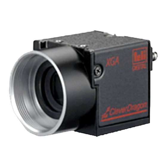
1. PRODUCT DESCRIPTION
CleverDragon series CSCS20BC2 is an integrated type B/W CCD camera with a SXGA format
all-pixel-data readout CCD. The model is suited for high-resolution image processing use. Its compact,
light-weight body is ideal for system integration.
2. FEATURES
(1) All-pixel reading
The all-pixel reading system allows the CSCS20BC2 to read all pixels in just 1/19.5 second.
CSCS20BC2 is equipped with a full-frame shutter that allows all-pixel reading even during shutter
operations.
(2) Full-frame shutter
Since all pixels are output even by a random trigger shutter operation, high resolution can be achieved,
without deteriorating the vertical resolution.
(3) Tetragonal lattice layout
The tetragonal lattice layout of CCD pixels facilitates computation for image processing.
(4) Camera Link interface (power supply type)
By using a Camera Link-capable frame grabber board to which power can be supplied, high-speed
transfer of captured images to a PC as well as various types of camera control from the PC are allowed.
Power can also be supplied to the camera with only one cable.
(5) Random trigger shutter function
CSCS20BC2 is equipped with a random trigger shutter, which starts exposure synchronized with
external trigger signals. Fast-moving objects can thus be captured in place, which ensures accurate
image processing.
(6) Restart-Reset
Images can be shot and fetched at arbitrary timing based on external VD signal input.
(7) Partial scan
Further speed-up is possible because ranges except the range of the image output that the user set are
not read.
(8) Ultra-compact and lightweight main unit
The space-saving ultra-compact and lightweight camera has excellent resistance against vibration and
impact.
(9) RoHS compliant
CleverDragon series are complied with EU RoHS.
3. CONFIGURATION
(1)Camera body ······························ 1
(2)Accessory
Manual
································ 1
4. OPTION PARTS
(1)Camera-mounting kit ······················ Model name: CPT8560
*Contact your dealer / distributor for details of option units.
*Application software is not supplied as a standard item.
5. INTERFACE
Video output/controlling/power supply connector: (Camera Link Base Configuration) CAMERA LINK
Outputs video signals and VALID, based on the camera link standard LVDS.
This connector is connected to the frame grabber board, image processing device and others.
And it is possible to supply the power to the camera, by using an exclusive Camera Link cable and frame
grabber board complied with Power over Camera Link standard.
Connector model: HDR-EC26FDTG2+ (Manufactured by Honda Connectors)
Pin #
I/O
Signal name
Pin #
I/O
Signal name
1
-
+12V
14
-
GND
2
O
TxOUT0-
15
O
Tx OUT0+
3
O
TxOUT1-
16
O
Tx OUT1+
4
O
TxOUT2-
17
O
Tx OUT2+
5
O
TxCLK OUT-
18
O
Tx CLK OUT+
6
O
TxOUT3-
19
O
Tx OUT3+
7
I
SerTC(RxD)+
20
I
SerTC(RxD)-
8
O
SerTFG(TxD)-
21
O
SerTFG(TxD)+
9
I
CC1(TRIG/VD)-
22
I
CC1(TRIG/VD)+
10
I
CC2+
23
I
CC2-
11
I
CC3-
24
I
CC3+
12
I
CC4+
25
I
CC4-
13
-
GND
26
-
+12V
*Please confirm the power supply of the camera cuts when the connector is connected or pulls out. It causes
the breakdown etc.
6. CONNECTION EXAMPLES
CCD camera
CSCS20BC2
Power-over Camera Link Cable
AC100V
DC+12V
50/60Hz
from ATX power suply
etc.
Frame Grabber Board
PC etc.
compiled with PoCL
7. FUNCTIONS
By accessing the camera register published on the camera link I/F, you can control/set each function.
Since access to the camera register is performed via the frame grabber board, the controlling and setting
methods differ depending on the frame grabber board you use. For details, refer to the instruction manual of
the relevant frame grabber board or contact our sales representative.
This instruction manual describes the specifications in the case where the camera register is directly
connected by serial transmission over the camera link interface.
For details of the control and setting of functions, refer to "Interface Specification". Please ask your
distributor or a sales representative about "Interface Specification".
7-1. Explanation of Each Function
(1) Readout mode
Address: 0x90, Bit: 0, Value:0 to 1
Video is output from the camera link connector. The output video can be grabbed by the frame grabber
board. The frame rate and resolution of output images that this model supports are as follows:
All pixel read out
19.5 fps (maximum frame rate) / 1360(H)1024(V)
Partial Scan
19.5 fps to 34.8fps (depend on Video output width)
Horizontal resolution: 1360 (fixed)
Partial Scan Video Start Line: 0 to 512
Partial Scan Video Width: 512 to 1024
(1-1) All pixel read out
Address: 0x90, Bit: 0, Value: 0
As all pixels are read out in approx. 1/19.5s, you will get images with the higher V resolution (you have
to change the shutter speed to 1/19.5s or shorter).
Vertical Timing (maximum speed on all pixel readout mode)
A = approx. 271.1us
B = approx. 50.9ms (1024H-336CLK)
C = approx. 136.0us
1frame = A + B + C = approx. 51.3ms
*1H = 1790CLK
FVAL
LVAL
DVAL
DATA OUT
A
B
Horizontal Timing
Same timing
FVAL
a
LVAL
DVAL
DATA OUT
b
d
e
c
f
a = 336CLK
b = 22CLK
c = 16CLK
d = 1360CLK
e = 16CLK
f = 40CLK
(1-2) Partial Scan
Address: 0x90, Bit: 0, Value: 1
Ranges except the range of the image output that the user set are not read.
Partial scan setting procedure is following:
Video start line
Address: 0xC4, Bit: 0 to 9, Value: 0 to 512
Video output width
Address: 0xC8, Bit: 0 to 10, Value: 512 to 1024
Partial scan update
Address: 0xC0, Bit: 0, Value: 1
If you want maximum frame rate, you must shorten the shutter speed.
ex. 1) Video Start Line =128, Video Width = 768 (maximum speed on all pixel readout mode)
FVAL
LVAL
DVAL
DATA OUT
A
B
D
A = approx. 996.4us
B = approx. 38.2ms ( 768H-336CLK )
C = approx. 861.3us
D = approx. 40.0ms
ex. 2) Video Start Line=256,Video Width=512 (maximum speed on all pixel readout mode)
FVAL
LVAL
DVAL
DATA OUT
A
B
C
D
A = approx. 1721.8us
B = approx. 25.5ms (512H-336CLK) C = approx. 1586.7us
D = approx. 28.8ms
(2) Setup Addition Value
Address: 0x70, Bit: 0 to 7, Value: 0 to 255
You can add the offset level to the reference black level.
Setup Addition
Setting Range
Calculation formula
(calculated value)
(a)
+0 to +255 [digit]
0x00 to 0xFF
+ a [digit]
(10bit)
(0 to 255)
(10bit)
+0 to +63 [digit]
0x00 to 0xFF
+ a/4 [digit]
(8bit)
(0 to 255)
(8bit)
(3) Gain
Address:0x76, Bit:0 to 6, Value:0 to 90
You can set Gain (video gain).
Gain
Setting Range
Calculation formula
(calculated value)
(b)
0x00 to 0x5A
0.132dB b [dB]
0 to approx. +12dB
(0 to 90)
Notes on gain setting:
It is possible to set a maximum of +12 dB (Calculation value) but the warranty range
for this product is 0 to +10 dB. When using this product, be sure to set a gain value
within the warranty range.
And, setting a too high gain value can increase noise. When you adjust the brightness
of the shot image, you are responsible for finally confirming the image quality by using
the entire machine/equipment.
C
C
D3004086D
Advertisement

Related Manuals for Toshiba teli CSCS20BC2


Summary of Contents for Toshiba teli CSCS20BC2
- Page 1 For details of the control and setting of functions, refer to “Interface Specification”. Please ask your The all-pixel reading system allows the CSCS20BC2 to read all pixels in just 1/19.5 second. limited to loss of expected income and suspension of business activities.
- Page 2 Readout mode Ci ≤ 57F, Rx = 10k ± 10% 1360(H) 1024(V) [19.5fps] All pixel readout (default): 1360(H) 768(V) [25.0fps] (MAX) PoCL CSCS20BC2 Partial Scan (ex.1) DATA OUT Test Circuit Cable 1360(H) 512(V) [34.8fps] (MAX) (ex.2)
Need help?
Do you have a question about the CSCS20BC2 and is the answer not in the manual?
Questions and answers