Table of Contents
Advertisement
Advertisement
Table of Contents

Subscribe to Our Youtube Channel
Related Manuals for Ares Crossfire


Summary of Contents for Ares Crossfire
- Page 1 Owner’s Manual & Technical Information (AU)
- Page 2 Specification All-up weight: .......560g Weight without battery: ..390g Size (motor diagonals): ..280mm Length: .........232mm Width: ........234mm ESCs (x4):......12A continuous; 15A peak; ONE-SHOT enabled Camera: .......Semi wide-angle lens Video Transmitter: ....25mW – 32 channels on 4 bands Video antenna: ....Protected cloverleaf, circular polarized Flight time: ......5–7 minutes Propellers: ......6 x 4.5”...
-
Page 3: Table Of Contents
In This Manual Introduction ................4 Contents ..................4 Required to complete ..............5 FCC Information ................. 5 Safety precautions ..............5 LiPo battery warnings ..............6 Identification of components............. 7 Set-up and Programming ............8 Flight Preparation ..............22 VTX channel selection .............. 24 Adjusting the camera angle .............25 Recommended accessories ............25 Lawful Operation ..............26... -
Page 4: Introduction
To top off the attractive design, bright red LED tail lights help with visibility and make sure your competitors know who’s in front of them on the course. As for a video system, the Crossfire comes with a pre-installed ultra-micro 25mW, 32-channel, 4-band VTX (video transmitter) and a 640 x 480 camera with 120 degree FOV (field-of-view) that combine to provide a crisp FPV experience. -
Page 5: Required To Complete
1 x Suitable 3S LiPo battery charger. You will also need access to Cleanflight open-source software in order to configure your Crossfire’s flight control board. FCC Information This device complies with part 15 of the FCC rules. Operation is subject to the following two conditions: 1. -
Page 6: Lipo Battery Warnings
• Never operate your model if the voltage of the batteries in the transmitter is too low. • Always operate your model in an open area away from obstacles, people, vehicles,buildings, etc. • Carefully follow the directions and warnings for this and any optional support equipment (chargers, rechargeable batteries, etc.). -
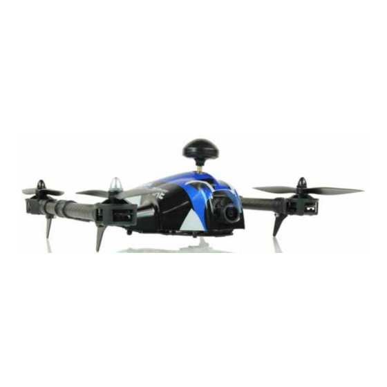
Page 7: Identification Of Components
Identification of Parts Cloverleaf antenna Counter-clockwise Clockwise motor motor Canopy mount Video transmitter RP SMA antenna mount Outrigger support Video Transmitter Counter- Channel Selectors clockwise motor Video camera Flight Control Board Outrigger arm Spektrum Satellite port Clockwise motor USB port... -
Page 8: Set-Up And Programming
Having done this, ensure that: • The model memory you’ve chosen for your Crossfire is set to ACRO mode. • The wing type is set to single servo aileron control. - Page 9 6. Receiver installation. Secure your receiver to the upper frame using hook and loop tape and secure the antenna wire(s). Note that only low-profile end pin receivers are suitable for the Crossfire due to the close proximity of the fuselage shell when fitted.
- Page 10 8. Download the Cleanflight Configurator software. Before flying your Crossfire you’ll need to configure and tune the Flight Control Board using Cleanflight open-source software. This software can be sourced via Google Chrome using the following method: a.
- Page 11 USB cable to the micro USB socket the Crossfire’s Flight Control Board and the large end to a spare USB socket on your computer. When the cable is connected the Cleanflight ‘Setup’...
- Page 12 11. Cancel the beeper. When you first connect the Flight Control Board, a beeper will be heard. This is a warning alarm that indicates the following: • Slow beep – Loss of signal from your transmitter. • Fast beep – Incorrect throttle position. Alarms can also be configured to highlight a number of alternative user-defined issues from locating a lost model to indicating a battery low voltage warning.
- Page 13 12. Calibrate the accelerometers. Place your Crossfire on a level surface and select the ‘Calibrate Accelerometer’ option. The Flight Control Board will beep in confirmation and calibrate the accelerometers accordingly. • Use the live graphic to ensure that the accelerometers are working as they should, i.e.
- Page 14 14. Basic set-up. Select ‘Configuration’ from the menu bar on the left-hand side of the Cleanflight interface and check/adjust the following. • Mixer – Set to ‘Quad X’ • Board and Sensor Alignment – No adjustment required. • Receiver Mode – Select the receiver you’re using. ▪...
- Page 15 • Serial Receiver Provider – Select the option that suits the receiver you’re using, i.e. for Hitec, Futaba and Spektrum receivers with 1024 resolution, select SPEKTRUM1024 • RSSI – Leave switched OFF • GPS – Leave switched OFF • ESC/Motor Features – Configure as noted below. ▪...
- Page 16 • Accelerometer Trim – Leave both Accelerometer Roll Trim and Accelerometer Pitch Trim set to zero. • Battery Voltage – Set VBAT (Battery voltage monitoring) to ON and adjust the Cell Voltages to: ▪ 3.3 – Minimum Cell Voltage ▪ 4.3 – Maximum Cell Voltage ▪...
- Page 17 ▪ 3500 – Flight Controller Loop Time ▪ 286 – Cycles/Sec (Hz) • Other Features – For US versions of the Crossfire that feature 6 motor output connectors on the right-hand side of the Flight Control Board, set SERVO_TILT to ON. For Flight Control Boards with 7 motor output connectors on the right-hand side of the Flight Control Board, set SERVO_ TILT to OFF.
- Page 18 15. Initiate failsafe. Select ‘Failsafe’ from the menu bar on the left-hand side of the Cleanflight interface and switch ON. Set Failsafe Throttle to 1000. Click ‘Save and Reboot’. 16. PID Tuning. Select ‘PID Tuning’ from the menu bar on the left-hand side of the Cleanflight interface and ensure that the PID Controller is set to MultiWii (2.3 –...
- Page 19 Allow the roll, pitch and yaw sticks on your transmitter to ‘centre’, then manually and precisely centre the throttle stick. Precisely centre the roll, pitch and yaw trims, then reduce the throttle trim to its lowest position. Now use the bar graph to check that roll, pitch, yaw and throttle are set to 1500, i.e.
- Page 20 ▪ Ensure your transmitter is powered ON and pull the throttle stick back to close the throttle. ▪ Install the charged 3S 2200mAh LiPo battery into your Crossfire and plug it in (see Step 30). On connecting the LiPo the Flight Control Board will emit a series of beeps.
- Page 21 27. Blackbox. No changes need to be made under the ‘Blackbox’ heading in the menu bar on the left-hand side of the Cleanflight interface. 28. Disable gyro compensation at zero throttle. The Crossfire’s flight control board is pre-programmed with gyro compensation at zero throttle. This must be programmed out.
-
Page 22: Flight Preparation
31. Arming the motors. WITH THE PROPELLERS STILL REMOVED, switch your transmitter ON and connect the Crossfire’s battery. A series of beeps will be heard confirming that the quad is ready to arm. Place the Crossfire on a level surface and arm the motors by moving the throttle stick to... - Page 23 33. Check gyro compensation at zero throttle. With the throttle stick at its lowest position, tilt the Crossfire from side to side and check that the motors remain inactive. If the motors rotate when the quad is tilted, this is clear evidence that gyro compensation at zero throttle is still active and that Step 28 will need to be repeated.
-
Page 24: Vtx Channel Selection
The arrangement of the five switches provides a new channel to which your Ares FPV monitor or your FPV goggles will auto-tune. Select the channel you require using the tables below noting that DIP switch 1, 2 and 3 are used to change between CH1 and CH8 whilst DIP switch 4 and 5 are used to select the frequency (FR). -
Page 25: Adjusting The Camera Angle
• Refit a new cable tie to secure the camera. Recommended Accessories To make the most of the FPV possibilities offered by your Crossfire we recommend a selection of the following accessories from the Ares Z-Line range: AZSZ1020 ......7”... -
Page 26: Lawful Operation
Please note that specific guidelines exist regarding the lawful flying of ‘Small Unmanned Aircraft’ and ‘Small Unmanned Surveillance Aircraft’ such as the camera-equipped Crossfire. To stay within the law visit the website of your country’s aviation regulating authority and read the operating guidelines within which you must operate. - Page 27 AZSZ2836 ......Canopy standoff AZSZ2838 ......FPV camera plate AZSZ2839 ......Battery tray AZSZ2842 ......25mW VTX AZSZ2843 ......Camera unit AZSZ2844......VTX aerial...
- Page 29 Ares-RC.com...
Need help?
Do you have a question about the Crossfire and is the answer not in the manual?
Questions and answers