Table of Contents
Advertisement
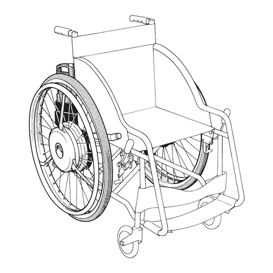
Electric power-assist unit for wheelchairs
SERVICE MANUAL
[XA41, XA42, XA43]
This manual has been compiled as a guide to installing the
on commer-
cial wheelchairs, and providing after-sales service. Information which dupli-
cates that contained in the
Service Manual has been omitted.
XA4-28197-00 (English)
Advertisement
Table of Contents

Related Manuals for Yamaha JW-II

Summary of Contents for Yamaha JW-II
- Page 1 Electric power-assist unit for wheelchairs SERVICE MANUAL [XA41, XA42, XA43] This manual has been compiled as a guide to installing the on commer- cial wheelchairs, and providing after-sales service. Information which dupli- cates that contained in the Service Manual has been omitted. XA4-28197-00 (English)
- Page 2 This service manual describes ordinary inspections and adjustments, as well as assembly procedures. April 1999 Yamaha Motor Co., Ltd. New Business Development Division The symbols noted below are used in this manual to indicate items which are necessary in order to handle the product correctly, and to carry out inspections and servicing.
-
Page 3: Table Of Contents
Index Introduction ..................1 Model Variations .................. 1 Principal Specifications ................2 Special Tools/Supplemental Materials ............3 Tightening Torques for Principal Portions ........... 4 Installation: Preparation ............5 Basic Judgment Concerning Applicability of ........5 Parts Supplied in the Same Package............6 Tools Required/Installation Based on Wheelchair Type ...... -
Page 4: Introduction
Introduction Model Variations • is available in nine variations. Please be careful to order the specific model desired. Variations and Principal specifications Model Name Assist Axle Tire Size Hand Rim Catalogue Type Ratio Indication -24S Detachable Type 24×1 3/8 WO ↑... -
Page 5: Principal Specifications
Model Variation/ Introduction Principal Specifications • Guidelines for selecting type A or B or C 1. A type is suitable for those who are capable of grasping the hand rims (such as paraplegics) and have enough strength to travel easily up a slope of about 4° (inclination of a slope inside a build- ing). -
Page 6: Special Tools/Supplemental Materials
Introduction Special Tools/Supplemental Materials Special tools Deep socket wrench with 10 mm bore (market product) This is necessary when tightening the stopper with the torque wrench. Supplemental Materials 1 Thread lock Locktite 241 Grease B (general type) 90890-69916 To be applied to threaded portions that easily come General waterproof grease can be used on sliding loose, such as screws for stoppers, as in the figure portions, spin axis bearings, and gear contact... -
Page 7: Tightening Torques For Principal Portions
Tightening Torques for Introduction Principal Portions • The following portions around the axle area are related to safety. When installing the unit, make sure these are sufficiently tightened, in the range specified below. If the tightening torque is too loose, there is a danger of loosening, and if tightening is too tight, there is a danger of breakage. Tightening portion Tool size Tightening torque... -
Page 8: Installation: Preparation
Basic Judgment Concerning Installation: Preparation Applicability of NOTE: Please be aware that there are wheelchairs in the market on which the cannot be installed. • can be installed on wheelchairs which meet all of the following conditions. 1. JIS standard vehicles with a tire size of 22 or 24 inches. 2. -
Page 9: Parts Supplied In The Same Package
Parts Supplied in Installation: Preparation the Same Package • Standard supplied parts differ to some extent, depending on whether the wheels are detachable or fixed. • Detachable type (22S, 24S, 22K, 24K) Name Part Number Quantity Name Part Number Quantity 1 Right (wheel + tilt lock) assembly 5 Clamp 90465-10098... -
Page 10: Tools Required/Installation Based On Wheelchair Type
Tools Required/Installation Based on Installation: Preparation Wheelchair Type • The following tools are required. (Those items which are not underlined are identical to those of the 1 Closed wrench (12-14) (14-17) (22-24) 2 Torque wrench, socket (12 deep) (17 deep) (24) (5mm hexagon) 3 Hexagon wrench (2) (4) (5) 4 Monkey wrench... -
Page 11: Installation Based On Wheelchair Type
Installation Based on Installation: Preparation Wheelchair Type 1. Angle adjustment of the battery bracket If the battery box is sharply tilted when the wheel assembly is installed, remove the three bolts indicated by the arrows, and straighten the battery box. 2. -
Page 12: Optional Parts
Installation: Preparation Optional Parts NOTE: When installing, the following parts may be necessary, depending on the wheelchair. Please request Yamaha for the parts when ordering delivery. 1. Detachable type with an axle hole diameter of 20 mm Name Part Number Quantity... -
Page 13: Others
Installation: Preparation Others • Other preparations • Cleaning the wheelchair If the wheelchair requires cleaning, this should be done before installation. CAUTION: The wheelchair should not be washed with water after it has been assembled, as this can cause breakdowns. •... -
Page 14: Installation: Procedure
Installation: Procedure Detachable Type 1. Remove the wheel and bolt clamp bracket from the wheelchair. 2. Remove the tilt lock assembly which is ten- tatively installed on the wheel assem- bly. Tilt lock assembly NOTE: Place the tilt lock assembly in order to recognize which is right and left. - Page 15 Installation: Procedure Detachable Type 6. Tentatively tighten the clamp bracket. 7. Fit the portion of the clamp bracket into the center hole of the tilt lock assembly. Place the washer on the flange bolt and tighten it tentatively. 8. Tighten the bolts, confirming that the tilt lock assembly (rollover prevention bar) is paral- lel to the base pipe of the wheelchair.
- Page 16 Installation: Procedure Detachable Type 11.Connect the wire by matching the white line on the coupler.
-
Page 17: Fixed Type
Installation: Procedure Fixed Type 1. Remove the wheel from the wheelchair. 2. Remove the tilt lock assembly that is tenta- tively tightened on the wheel assembly. NOTE: Place the tilt lock assembly in order to recognize which is right and left. 3. -
Page 18: Installation: Inspection And Adjustment After Installing
Installation: Inspection And Inspection Points and Adjustment After Installing Adjustment Points NOTE: Before starting assembly, make the necessary adjustments, based on the type of wheelchair, with reference to the table on page 7. After the assembly has been completed, inspect it, and if any adjustments are needed, follow the proce- dure outlined below. - Page 19 Installation: Inspection And Inspection Points and Adjustment After Installing Adjustment Points 3. Adjust the direction of the warning light (LED). Turn the warning light with your finger until it can be easily seen when sitting in the wheel- chair. ✽ This is attached to the left wheel. 4.
- Page 20 Installation: Inspection And Inspection Points and Adjustment After Installing Adjustment Points Using the clamp which has been tentatively tightened, secure it to the plate battery fitting (indicated by the arrow at the left). 6. The front caster of the wheelchair should not lift more than 50 to 100 mm from the ground while adjusting length of the tilt lock assem- bly (rollover prevention bar).
- Page 21 Installation: Inspection And Inspection Points and Adjustment After Installing Adjustment Points 2. Adjust the wire adjuster until the clearance between the brake rubber and the rim is the Lock nut same for the left and right wheels. At this Adjuster point, also adjust the play of the brake lever.
-
Page 22: Service At Delivery
Service At Delivery Outline of the Running Control System... - Page 23 Service At Delivery Outline of the Running Control System NOTE: • Most of the wires are micro current signal lines. • When handling them, be careful not to cut or damage the wires. • Always remove the battery when disassem- bling or performing maintenance.
-
Page 24: Explaining Operation Characteristics To The User
Explaining Operation Service At Delivery Characteristics to the User • Explain the operation characteristics in accordance with the Owner’s Manual. The following items are only the main points. Points of operation 1. If this wheelchair is operated in the same way as a manual wheelchair, customer will experience an excessively strong response, because of the power assist. - Page 25 Explaining Operation Service At Delivery Characteristics to the User Switch operation and the system function 1 Power switch • When the power switch is in the OFF position, the is in the same state as a manual wheelchair, and the wheelchair can be used manually. •...
- Page 26 Explaining Operation Service At Delivery Characteristics to the User Buzzer Sounds Buzzer sound When it sounds “Pi” 1 When the power switch is turned on. (LED lights for 3 seconds) One short sound 2 When the power is turned off by auto-off function. “Pi Pi Pi Pi”...
-
Page 27: Battery
Battery Names of Parts and Circuits Release button Battery fuse (30 A blade-type) Attachment screw Contact point – Blue, Spare battery fuse Protective cap Black thin White, thin 30 A fuse Red, thin Battery control unit Battery management Remaining capacity Thermistor controller Display switch... -
Page 28: Construction And Characteristics Of Nickel Hydrogen Batteries
Construction and Characteristics of Battery Nickel Hydrogen Batteries Nickel hydrogen batteries are handled very dif- ferently from ordinary automotive batteries + positive electrode (lead batteries). terminal (built into gas Spring discharge valve) Restraining plate The construction of the nickel hydrogen Sealing plate Valve post battery... -
Page 29: Battery Construction And Characteristics
Battery Construction and Battery Characteristics Discharging Unlike ordinary dry cell batteries, nickel hydro- gen batteries exhibit uniform voltage character- istics when ongoing discharging of constant current is carried out, and the voltage then drops sharply when there is no longer any ca- Charging: 0.1 C ×... - Page 30 Battery Construction and Battery Characteristics Memory effect If nickel hydrogen batteries are repeatedly charged before the battery power has com- pletely drained, a phenomenon occurs in which both the capacity which can discharged from (Example) the battery and the voltage characteristics of the battery decrease.
- Page 31 Battery Construction and Battery Characteristics Storing the battery When nickel hydrogen batteries are stored, they self-discharge, so that accumulated en- ergy is lost and the battery capacity decreases. The amount of self-discharging is affected by Charging: 0.1 C × 16 h the temperature under which the battery is Discharging: 1 C (E.V.-1.0 V) Storage temperature: 0.25, 40°C...
-
Page 32: Battery Functions
Battery Battery Functions The battery control unit provided on the battery Remaining battery has three general functions: 1 it serves as a capacity indicators Display switch remaining capacity gauge, 2 it communicates battery information, and 3 servicing. Remaining capacity gauge The capacity gauge has two functions, one which controls the remaining capacity by calcu- lating the current, and another called a “capac-... - Page 33 Battery Battery Functions If the deterioration display appears at an early stage, the service mode can be used for a simple diagnosis of the problem. (See the later section on servicing the battery.) CAUTION: If there is only one stage on the capacity display gauge which is flashing (remaining capacity alert), the battery should be charged immediately, or should be replaced with a...
-
Page 34: Service Mode
Battery Battery Functions Service mode The battery control unit is equipped with a service mode which can be used to make a simple diagnosis of the battery. <Usage of the service mode> Procedure Hold down the display switch for at least 10 seconds (the capacity display goes out after 5 seconds). When the capacity display appears again, press the switch twice before the display goes out. - Page 35 Battery Battery Functions LED check Confirms whether or not an LED has burned out (all LEDs light) Simple battery Top LED lights diagnosis Battery is normal Middle LED lights Battery needs refresh charging Advise that refresh charging must definitely be done when the next alert is displayed.
- Page 36 Battery Battery Functions Display of no. of times The number of times the battery has been used is displayed, counting one used charging and discharging as one cycle. Flashing Lighted lighted 400 or more to 99 to 149 to 199 to 249 to 299 to 349...
- Page 37 Battery Battery Functions • Failure analysis of the battery control unit • The capacity cannot be displayed. • The battery cannot be charged. If either of the above instances occurs, follow the procedure below to judge the failure of the battery control unit: 1.
-
Page 38: Battery Charger
Battery Charger Names and Functions of Parts • The XA4 charger (JWC-2) is a dedicated charger made specifically for the XA4 bat- tery, and is designed to extend the service life of the battery and to enable faster charging. Exhaust port AC cord (detachable type) Contact points (4 locations) Battery insertion port... - Page 39 Battery Charger Names and Functions of Parts Function 2. Refresh function Charging the battery after it has been completely discharged improves the activiation in the battery and restores the battery performance. Also, the communication function in the XA4 charger receives data from the battery control unit at the optimum refresh timing, and has a function which alerts the user that refresh charging is needed.
- Page 40 Battery Charger Names and Functions of Parts Function 6. Display function <Lamp displays> Green lamp Yellow lamp Preliminary charging in progress, temperature Flashing Not Lighted standby Fast charging in progress, follow-up charging Lighted Not Lighted in progress Charging completed, trickle charging in Not Lighted Not Lighted progress...
- Page 41 Battery Charger Names and Functions of Parts • Diagnosing communication problems in the charger • If the battery cannot be charged because of a communication problem, the following causes should be considered: 1 the charger, 2 the battery, and 3 the contact points. Follow the proce- dure below to inspect the charger, battery, and contact points.
-
Page 42: After Service
After Service Self diagnosis function is equipped with a self-diagnosis function that monitors the control system. If a problem occurs in the system, power-assisted travel is discontinued. If this happens, turn off the power switch and use manual travel. • If a problem is detected, the external LED lights or flashes, and both wheels stop simultaneously. -
Page 43: What To Do When Led Warning Light Is On
Cir-clip that side of the wheel. 2. Contact the Yamaha Service Center or the head office and report the malfunction, to- gether with the model type, production num- ber, sales date and other information. -
Page 44: Adjustment Points When Replacing Wheels
Adjustment Points When After Service Replacing Wheels • When replacing only one wheel assembly, replace with a wheel assembly with the identical specifications. It will not activate properly if it has different specifications. Also, neutral adjustment of the sensor is necessary when replacing just the wheel. Making neutral adjustments to the sensor. -
Page 45: Ordering Parts
After Sales Service Ordering Parts • When ordering parts, indicate the part name and the part number listed in the parts catalogue. Part Number XA4-25350-00 Example Revision number (If there is a first revision, the number will change Model from 0 to 1.) number Design number (If it is necessary to distin-... -
Page 46: Service Manual
YAMAHA MOTOR CO., LTD. 2500 SHINGAI IWATA SHIZUOKA JAPAN SERVICE MANUAL [XA41, XA42, XA43] First edition, April 1999 All rights reserved. Written and published by Printed on recycled paper Yamaha Motor Co., Ltd. 9904-0.5×1 CR...
Need help?
Do you have a question about the JW-II and is the answer not in the manual?
Questions and answers