Table of Contents

Related Manuals for Heat Line Monza 24


Summary of Contents for Heat Line Monza 24
-
Page 1: Installation And Servicing
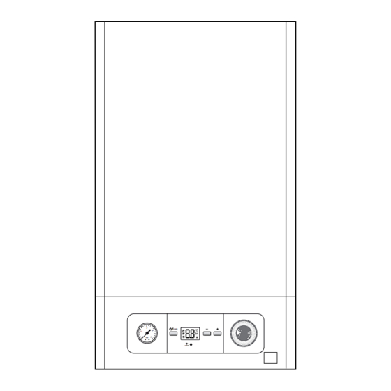
Monza Installation and Servicing Models G.C. No. 47-157-21 G.C. No. 47-157-22 mode reset High Effi ciency Condensing Combination Boilers www.heatline.co.uk Service Call 0844 736 9042, Technical Help (Chargeable) Call 0906 802 0253... -
Page 2: Guarantee Registration
Guarantee Registration Thank you for installing a new Heatline appliance in your home. Heatline appliances are manufactured to the very highest standard so we are pleased to offer our customers a Comprehensive Guarantee. For the manufacturer's warranty to be valid, the Benchmark Log Book must be correctly completed by a suitably qualifi ed person and be available for inspection prior to any repair. -
Page 3: Instructions Guidance
INTRODUCTION We recommend you complete and return as soon as possible your guarantee registration card. If your guarantee registration card is missing you can obtain a copy or record your registration by telephoning the Heatline Customer Service number 0844 736 Instructions guidance 9042. -
Page 4: Hydraulic Schematic
Data label Product/production certifi ed by: Notifi ed body IMQ 52BP2727 CE Directives 2009/142/EEC. The data label certifi es the country where the appliance is 52BP2728DR CE Directives 92/42/EEC. intended to be installed. It is located on the rear of the drop The CE mark indicates that the appliances described in this down control box manual are in compliance with the following directives:... -
Page 5: Statutory Requirements
• This appliance contains metal parts (components) and care 19 Ignition module 20 Heating fl ow thermistor (Red) should be taken when handling and cleaning, with particular 21 Air vent regard to edges. 22 Pump 23 Three way valve The basic safety instructions must be followed before attempting 24 Water pressure sensor to maintain or replace spare parts: 25 Heating return isolating valve and fi lter (Blue) -
Page 6: Other Regulations
In IE, the installation must be carried out by a competent person The boiler MUST be connected to a permanent 230V ac, 50Hz approved at the time by the Health and Safety Executive and supply. installed in accordance with the current edition of I.S.813 Connection of the whole electrical system of the boiler, including “Domestic Gas Installations”, the current Building Regulations any heating controls, to the electrical supply MUST be through... -
Page 7: Technical Data
Appliance Description Unit Most of the appliance is manufactured from recyclable materials. Electrical 230V 230V Electrical supply V/Hz 50Hz 50Hz This symbol indicates that this appliance must not Standby mode electrical power be disposed of with household waste, that it should be selectively collected for energy recovery, reuse or Operating mode electrical power recycling. -
Page 8: Installation
Monza Clearances • The clearances specifi ed are the minimum required to allow Boiler, type C13, C33 general service and maintenance of the appliance. • To allow periodic maintenance, ensure the distances indicated on the diagram. INSTALLATION Additional clearances may be benefi cial around the boiler for installation and servicing. -
Page 9: Appliance Installation
The domestic hot water fl ow has a restrictor, factory fi tted, which reduces the fl ow to a maximum of: - Monza 24 ► 8l/min / Monza 28 ► 10l/min, Central Heating water fl ow rate If it is necessary to alter the fl ow rate, the system can be fi tted with a lockable balancing valve in the main fl ow or return pipes. - Page 10 • Ensure all cleanser is removed from the whole system before General adding an inhibitor. This boiler is designed for use as part of a sealed water central For long-term corrosion protection after fl ushing, an inhibitor heating system with fully pumped circulation. The pump, suitable for stainless steel heat exchangers can be used.
-
Page 11: Fixing To The Wall
The fl ue is designed with an internal fall of 44mm/ metre (2.5 ), therefore the hole can be drilled horizontally. • Use a 105mm diameter core drill for external access fl ue installation (60/100 fl ue). • Use a 125mm diameter core drill for internal access only fl ue installation (60/100 fl ue). -
Page 12: Hydraulic Connection
Boiler hanging Ensure that the appliance is disconnected before cleansing the system. With regards to the Manual Handling Operations, • Do not use any solvent products, due to the risk of damaging 1992 Regulations, the following lift operation the circuit. exceeds the recommended weight for a one person lift, refer to chapter "Manual Handling". - Page 13 Service Call 0844 736 9042, Technical Help (Chargeable) Call 0906 802 0253 - 13 -...
-
Page 14: Connection To The Condensate Trap
Connection to the condensate trap • Should the condensate be drained externally then keep the length of external pipe as short as possible. A minimum of 32mm diameter insulated pipe should be used, with a steep a Condensate produced by the appliance is mildly decent as possible to the termination point. - Page 15 Evacuation of combustion products The terminal must be exposed to the external air, allowing free passage of air across it at all times. Being a condensing boiler some pluming may occur from Regulation the fl ue outlet. This should be taken into consideration when selecting the position for the terminal.
- Page 16 Position Position of the fl ue terminal Position Position of the fl ue terminal from surface or a boundary facing the terminal Horizontal fl ues from opening (door/window) in car port directly below an opening, air brick, 1200 into dwelling opening windows vertical from a terminal 1500...
-
Page 17: Flue Confi Guration Description
Flue confi guration description 10 Remove/replace front panel and controls fascia Horizontal concentric fl ue Ø 60/100 mm (C13 type installation) If necessary, you must install a terminal protection kit. Ø 60/100 mm Controls fascia Controls fascia retaining screw • Release the controls fascia (1) by loosening the securing screws (2). -
Page 18: Electrical Wiring
The external wiring must be earthed, with correct polarity and in • Keep a distance of a maximum of 30 mm between connector accordance with current standards. (1) and the start of the insulation (3). The manufacturer declines any responsibility for damages to •... -
Page 19: External Accessories
10.5 External accessories 230V permanent supply + 230V system controls Under no circumstances must any mains voltage All cables connected to the appliance should be be applied to any of the terminals on the 24v permanently fi xed to the wall. connection plug. -
Page 20: Wiring Diagram
10.7 Wiring diagram DESCRIPTION : BLACK : BROWN : RED Y/G : YELLOW/GREEN : BLUE : GREEN : GREY : WHITE : PINK : ORANGE : PURPLE : YELLOW Service Call 0844 736 9042, Technical Help (Chargeable) Call 0906 802 0253 - 20 -... -
Page 21: Filling The Ch System (Central Heating)
11 Commissioning Air vent Pump At the time of commissioning, complete all relevant Screw for the pump shaft sections of the Benchmark Checklist located in the • Open the plug on the air vent located on the pump and centre pages of this document. automatic air vents on the installation. -
Page 22: Adjusting The Temperature
• Activate the Heating and Domestic Hot Water functions. Display • Run the appliance for at least 15 minutes, with a heating temperature set to greater than or equal to 50°C (not • Light the appliance by following the procedure below. applicable for an installation with underfl oor heating). -
Page 23: Testing Heating System
Operational Gas Inlet Pressure In communal or LPG installations where the gas rate cannot be measured it is acceptable to measure the combustion rate as described in section 18.2.3. • On completion, press the "reset" button with a blunt instrument to reset the boiler. 11.7 Testing heating system •... -
Page 24: Specifi Ed Adjustment
Heating circuit adjustment By pass operation is automatic and not adjustable. If necessary, fi t an external by-pass. Monza 24 : 25kW HEATING // 35W V1 / bypass closed HEATING //35W V2/ bypass closed HEATING //35W V2 / bypass middle position... -
Page 25: Installation Settings
13 Installation settings • Press on to validate. The screen displays a fl ashing and alternating "d." and "00". • To adjust the operational parameters: • Press on button to access the parameter to modify. • Press for more than 7 seconds on the button •... - Page 26 Factory Modifi able Code Service Parameters Unit Description setting parameter 0 = off d.22 DHW demand active (tapping) 1 = on 0 = CH not available (summer mode) d.23 Central heating mode 1 = CH available (winter mode) Fan speed is displayed between 0 and 99. d.33 Speed setpoint of fan Multiply the displayed value by 100.
-
Page 27: Test Modes
13.1.2 Test modes If you wish to check the combustion then follow the instructions in the Servicing section. By activating these various test modes, you can enable special functions on the appliance. 13.2 Re-check and restart • Press the on/off button to switch off the appliance. •... -
Page 28: Fault Diagnosis
• Leave these instructions and the ‘Benchmark’ Installation, • If the symbol is displayed on the screen, display the Commissioning and Service Record with the user. fault code memory (see chapter " Trouble-shooting ►Fault memory"). • Re-pressurise the system as instructed by your installer. •... -
Page 29: Fault Memory
15.2 Fault memory 15.1.2 Check the gas supply • This menu allows you to display the 10 most recent failure codes registered by the appliance. • In order to display the fault code memory, simultaneously press the buttons for more than 7 seconds. •... -
Page 30: Fault Codes
Fault Description Cause Solution codes Flow heating temperature sensor fault Sensor open circuit Return heating temperature sensor Return heating temperature sensor fault • Check the sensor’s connections. disconnected • Check the wiring harness. Flow heating temperature sensor fault Sensor short-circuit •... -
Page 31: Functional Flow Diagram
Fault Description Cause Solution codes Heating circuit pressure sensor fault The sensor is shorted or disconnected. • Check the sensor’s connections. • Check the sensor. Heating circuit pressure sensor fault Fault in pressure sensor Thermal fuse disconnected • Check the fuses connections. Thermal fuse fault Defective thermal fuse •... -
Page 32: Gas Conversion Adjustments
15.4.2 Domestic Hot Water 16 Gas conversion adjustments Conversion of this appliance to run on LPG requires a conversion kit . The kit and the conversion operation must be done by the Heatline Service Team, please ring : 0844 736 9042 . -
Page 33: Heating Circuit
• To obtain service, please call your installer or Heatline’s 17 Draining own service organisation. PLEASE NOTE: During routine servicing, and after any 17.1 Heating circuit maintenance, we recommend that the following must be checked: - The integrity of the fl ue system and the fl ue seals, - The integrity of the boiler combustion circuit and the relevant seals, - The operational (working) gas inlet pressure at maximum... -
Page 34: Combustion Check And Setting The Air/Gas Ratio Valve
• Check that there are no gas leaks. • Ensure that the gas analyser is set to the correct fuel setting. • Verify that the fl ue system is sound and complete. • Select the “ ”, constant central heating with DHW function by pressing the “... -
Page 35: Service Interval Record
18.2.5 Completion 2A Flue elbow 2B Vertical fl ue adaptor If it is not possible to achieve the required results for either the combustion or gas rates, it will be necessary to complete a full service of the appliance and then repeat the combustion check 18.2.3 Maximum rate check and adjustment procedure. -
Page 36: Expansion Vessel
18.5 Expansion vessel There is a fi lter fi tted that protects the plate heat exchanger from blockage. • After draining the boiler as previously described push and turn the fi lter cap in an anti-clockwise direction to release it from its housing. -
Page 37: Condensate Trap
18.8 Condensate trap • Disconnect the condensate drain (3) and the rain water collector (4) from the heat exchanger. Warning: condensate is mildly acidic. Use The condense trap will contain water, lift taking care not to spill protective gloves. the water. •... -
Page 38: Combustion Block
18.9 Combustion block Legend Heat exchanger Gas valve connection 12 Burner door seal Grounding cable 13 Burner Spark electrode inlet 14 Gas valve Spark electrode retaining screw. 15 Fan Spark electrode gasket 16 Fan connection Spark electrode 17 Gas pipe Burner retaining nut Burner retaining screw Thermal fuse connection... -
Page 39: Service Completion
18.9.1 Spark electrode 18.9.5 Re-assembling the burner group • Disconnect the electrode inlet (3) and the grounding cable (2). • Place the burner group on the heat exchanger (11). • Remove the 2 spark electrode retaining screws (4). • Progressively tighten 4 nuts (7) in an alternate order. •... -
Page 40: Boiler Access
19.1 General 19.3.1 Expansion vessel The replacement of parts described in sections "Combustion block" will require the removal of the burner module assembly and the replacement of seal and self locking nuts. Replacement parts that have associated components that need replacing on removal, i.e. -
Page 41: Hydraulic Block
19.4 Hydraulic block 21mm 18mm 20 Pump head retaining screws Three-way valve motor 21 Pump housing Three-way valve electrical plug 22 Pump head connector Three-way valve electrical plug retaining clip 23 Plate-to-plate heat exchanger retaining screws Low water pressure sensor connector 24 Safety Discharge Valve Low water pressure sensor 25 Bypass Valve... -
Page 42: Automatic Air Vent
19.4.1 Pump (head only) 19.4.5 Flow sensor and impeller • Drain the boiler heating circuit as described in the appropriate • Remove the the electrical connection (12). chapter "Draining". • Unclip the fl ow sensor (13). • Disconnect the electrical plug (22) from the main board. •... - Page 43 19.5 Combustion block Legend Igniter unit retaining bracket 20 Thermal fuse connection Igniter unit 21 Heat exchanger Igniter unit retaining screw 22 Heat exchanger retaining bracket Igniter unit electrical connector 23 Heat exchanger retaining screw Electrode / igniter unit connection cable 24 Heating return pipe Earth cable 25 Heating return pipe retaining clip...
- Page 44 19.5.1 Spark electrode 19.5.5 Heat exchanger • Disconnect the electrode cap (7) and the earthing cable (6). There will be water in the heat exchanger. Carefully ease heat exchanger out. • Remove the 2 spark electrode retaining screws (8). • Carefully remove the electrode (10) from the combustion •...
-
Page 45: Gas Valve
19.6 Condensate trap When reconnecting, the polarity of the wiring to thermistors is not important. Warning: condensate is mildly acidic. Wear protective gloves. 19.5.9 Gas valve • Remove the burner door (11) refering to chapter "Dismantling the burner door". • Remove the two gas valve retaining screws (30). •... -
Page 46: Mains Supply Cable
19.7 19.7.3 User interface PCB When replacing the board refer to instructions supplied with the spare part. 19.7.1 Main PCB Retaining clips Main PCB User interface PCB Retainings clips Electrical connection Electrical connections Control box • Ease back the PCB retaining clips (1) and withdraw the user interface PCB (2) from the retaining lugs. -
Page 47: Spare Parts
20 Spare parts In order to guarantee the safe and prolonged life of the product, manufacturers genuine spare parts must be used. This appliance displays a CE Mark of conformity. Only use the manufacturer’s genuine, new spare parts. • Ensure that spare parts are correctly mounted in the right position and direction. -
Page 48: Manual Handling
Manual Handling Unpacking of appliance from carton. Recommend 2 persons unpack appliance from carton. Always keep working area clear. Cut the carton straps, lift carton up and slide over IMPORTANT. With regards to the Manual Handling Operations, 1992 polystyrene end packs. Remove top polystyrene pack with fittings. Regulations, the following lift operation exceeds the recommended weight for a one man lift. - Page 50 Failure to install and commission according to the manufacturer’s instructions and complete this Benchmark Commissioning Checklist will invalidate the warranty. This does not affect the customer’s statutory rights. If yes, and if required by the manufacturer, has a water scale reducer been fitted? CONDENSING BOILERS ONLY The condensate drain has been installed in accordance with the manufacturer’s instructions and/or BS5546/BS6798 If the condensate pipe terminates externally has the pipe diameter been increased and weatherproof insulation fitted?
-
Page 51: Service Record
Service Record It is recommended that your heating system is serviced regularly and that the appropriate Service Interval Record is completed. Service Provider Before completing the appropriate Service Record below, please ensure you have carried out the service as described in the manufacturer’s instructions. - Page 52 Heatline, Nottingham Road, Belper DE56 1JT www.heatline.co.uk Service Call 0844 736 9042, Technical Help (Chargeable) Call 0906 802 0253...
Need help?
Do you have a question about the Monza 24 and is the answer not in the manual?
Questions and answers