Table of Contents
Advertisement
Advertisement
Table of Contents
Troubleshooting

Subscribe to Our Youtube Channel
Related Manuals for MTU 20 V 4000 M73 x


Summary of Contents for MTU 20 V 4000 M73 x
-
Page 1: Operating Instructions
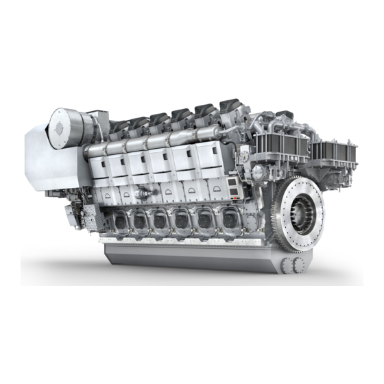
Operating Instructions Diesel engine 20 V 4000 M73 x MS150046/02E... - Page 2 This Publication is protected by copyright and may not be used in any way whether in whole or in part without the prior written permission of MTU Friedrichshafen GmbH. This restriction also applies to copyright, distribution, translation, mi- crofilming and storage or processing on electronic systems including data bases and online services.
-
Page 3: Table Of Contents
Table of Contents 1 Safety 4.15 Stopping the engine from LOP 4.16 Emergency stop from LOP 1.1 Important provisions for all products 4.17 Stopping the engine at the BlueLine 1.2 Personnel and organizational requirements automation system (control stand) 1.3 Safety regulations for startup and operation 4.18 After stopping the engine 1.4 Safety regulations for maintenance and 4.19 Fuel treatment system –... - Page 4 8 Appendix A 7.16 Battery-Charging Generator 7.16.1 Battery-charging generator drive – Coupling 8.1 Abbreviations condition check 8.2 MTU contact persons/service partners 7.17 Engine Mounting / Support 7.17.1 Engine mounting – Check 9 Appendix B 7.18 Auxiliary PTO 9.1 Special Tools 7.18.1 Bilge pump –...
-
Page 5: Safety
1 Safety 1.1 Important provisions for all products Nameplate The product is identified by nameplate, model designation or serial number and must match with the information on the title page of this manual. Nameplate, model designation or serial number can be found on the product. General information This product may pose a risk of injury or damage in the following cases: •... -
Page 6: Personnel And Organizational Requirements
1.2 Personnel and organizational requirements Organizational measures of the operator This manual must be issued to all personnel involved in operation, maintenance, repair or transporta- tion. Keep this manual handy in the vicinity of the product such that it is accessible to operating, mainte- nance, repair and transport personnel at all times. -
Page 7: Safety Regulations For Startup And Operation
1.3 Safety regulations for startup and operation Safety regulations for startup Install the product correctly and carry out acceptance in accordance the manufacturer's specifications before putting the product into service. Before the product is put into operation for the first time, all official authorizations must be available and commissioning preconditions met. -
Page 8: Safety Regulations For Maintenance And Repair Work
1.4 Safety regulations for maintenance and repair work Safety regulations prior to maintenance and repair work Have maintenance or repair work carried out by qualified and authorized personnel only. Allow the product to cool down to less than 50°C before starting maintenance work (risk of explosion of oil vapors, fluids and lubricants, risk of burning). - Page 9 Ensure particular cleanness during maintenance and repair work on the product. After completion of maintenance and repair work, make sure that no loose objects are in/on the product (e.g. cloths and cable ties) Safety regulations after completion of maintenance and repair work Before barring, make sure that nobody is standing in the danger zone of the product.
- Page 10 Working on electrical and electronic assemblies Always obtain the permission of the person in charge before commencing maintenance and repair work or switching off any part of the electronic system required to do so. De-energize the appropriate areas prior to working on assemblies. Do not damage cabling during removal work.
-
Page 11: Fire Prevention And Environmental Protection, Fluids And Lubricants, Auxiliary Materials
The latest version can be found on the website on the "Technical Info" tab at http://www.mtu-online.com. Consumable fluids and materials may also be hazardous or toxic. When using fluids, lubricants, consum- ables and other chemical substances, follow the safety instructions that apply to the product. -
Page 12: Check
Lead • Adopt suitable measures to avoid the formation of lead dust. • Switch on extraction system. • When working with lead or pastes that contain lead, avoid direct contact with the skin. Do not inhale lead vapors. • Wash hands after contact with lead or lead-containing substances. Compressed air Observe special safety precautions when working with compressed air: •... -
Page 13: Standards For Safety Notices In The Text
1.6 Standards for safety notices in the text DANGER In the event of immediate danger. Consequences: Death, serious or permanent injury! • Remedial action. WARNING In the event of a situation involving potential danger. Consequences: Death, serious or permanent injury! •... -
Page 14: Transport
Only set down engine on a firm, level surface. Make sure that the consistency and load-bearing capacity of the ground or support surface is adequate. Never place an engine on the oil pan, unless expressively authorized by MTU on a case-to-case basis to do so. -
Page 15: General Information
2 General Information 2.1 Engine side and cylinder designations Engine sides are always designated as viewed from the driving end (KS) (4). For designation of the cylinders (to DIN ISO 1204) the letter "A" (1) is used to refer to the cylinders on the left-hand side of the engine and the letter "B"... -
Page 16: Product Description
2.2 Product description Description of the engine Engine The engine is a liquid-cooled four-stroke diesel engine, rotating counterclockwise (seen from driving end), with direct injection, sequential turbocharging and charge air cooling. The engine is monitored by an engine control and monitoring system (ADEC). Monitoring in the engine room is carried out by the engine control and monitoring unit (LOP). - Page 17 • Interface to ECU and EMU • MCS5 dialog interface • Control of an MTU lube-oil priming pump (power components in separate MTU PPC Box) • Connection facility for an MTU Local Operating Station (LOS) • Serial RS422 interface for diagnosis The engine interface is divided into two parts.
- Page 18 • Interface to CAN field bus for connected, communicating monitoring system components. SOLAS – Fire safety requirements The following figures show all lines with SOLAS-compliant covers for pipe connections according to MTU standard MTN5233. Fuel system, fuel lines with fuel pressure >1.8 bar 1 Fuel line to fuel filter head...
- Page 19 1 Fuel line from fuel filter head 1 Fuel line to HP pump Lube oil system, oil lines with oil pressure >1.8 bar 1 Parting line ETC oil supply free end MS150046/02E 2013-07 | General Information | 19...
- Page 20 1 Parting line ETC oil supply driving 1 Oil line on equipment carrier 1 Oil supply to HP pump 20 | General Information | MS150046/02E 2013-07...
- Page 21 1 Oil supply to flap control, free end 1 ETC oil supply on main oil gallery 1 Switching cylinder air flap A2 MS150046/02E 2013-07 | General Information | 21...
- Page 22 1 Oil line connection 2 Switching cylinder exhaust flap tur- bocharger A2 3 T piece flap control 1 Connection oil line to turbocharger 2 Switching cylinder exhaust flap tur- bocharger B1 3 T piece flap control turbocharger B1 1 Switching cylinder air flap turbo- charger B1 22 | General Information | MS150046/02E 2013-07...
- Page 23 1 Connection oil line to turbocharger 2 Switching cylinder exhaust flap tur- bocharger B2 3 Switching cylinder air flap turbo- charger B2 4 T piece flap control turbocharger B2 1 Flap control distributor Special connections In case of leakage, the following connection types are spray-protected even without a cover and have been confirmed compliant with SOLAS by GL and DNV.
- Page 24 Plugs and sensors, plug-in pipe connections Plugs and sensors (a) Screwed-in seal plugs (4) are sealed toward the outside either with a copper sealing ring (1), according to DIN, or an O-ring (ISO). In case of a loose thread or a defective sealing ring (1), the liquid first has to pass the thread. The pressure is so greatly reduced by this and the faulty sealing ring (1) that any leakage is not under pressure.
- Page 25 HP connections 1 Jacket pipe 8 Thrust ring 15 Union nut 2 HP line 9 Union nut 16 Thrust ring 3 O-ring 10 Union nut 17 Outer high-pressure line 4 Union nut 11 Connecting piece pipe 5 Recess for O-ring 12 Snap ring 18 Internal pipe of HP line 6 Thrust ring...
-
Page 26: Engine Overview
2.3 Engine overview 1 Oil cooler 6 Charge-air pipework 11 Automatic oil filter 2 Crankcase breather 7 Cylinder head 12 HP fuel pump 3 Air filter 8 Oil filler neck 13 Fuel filter 4 Exhaust turbocharger 9 Engine mounting 14 Centrifugal oil filter(s) 5 Intercooler 10 Oil pan 15 Coolant cooler... -
Page 27: Sensors And Actuators - Overview
2.4 Sensors and actuators – Overview Top view 20V 4000 M 1 B4.A1 (exhaust tempera- 10 B4.A10 (exhaust tempera- 19 B4.B7 (exhaust tempera- ture cyl. A1) ture cyl. A10) ture cyl. B7) 2 B4.A2 (exhaust tempera- 11 B5.2 (lube oil pressure af- 20 B4.B6 (exhaust tempera- ture cyl. - Page 28 20V 4000 M left side 1 B7 (lube oil temperature) 8 B10 (charge-air pressure) 15 B57.7 (main bearing tem- 2 B50 (crankcase pressure) 9 B57.1 (main bearing tem- perature) 3 B44.3 (turbocharger C perature) 16 B57.8 (main bearing tem- speed) 10 B57.2 (main bearing tem- perature) 4 B4.23 (temperature, turbo-...
- Page 29 20V 4000 M free end 1 F46 (leak-fuel level) 4 B54 (oil refill pump pres- 7 Connector XD1 – Dialog 2 B33 (fuel temperature) sure) unit 3 B1 (camshaft speed) 5 B6.2 (coolant tempera- ture) 6 B6 (coolant temperature) MS150046/02E 2013-07 | General Information | 29...
- Page 30 20V 4000 M right side 1 B44.2 (turbocharger B 7 B21 (raw water pressure) 13 B77.B5 (spray oil temp. speed) 8 B77.B10 (spray oil temp. conrod bearing) 2 B4.22 (temperature, turbo- conrod bearing) 14 B77.B4 (spray oil temp. charger B) 9 B77.B9 (spray oil temp.
- Page 31 20 V 4000 M driving end 1 B13.2 (crankshaft speed) 3 S37.2 (safety switch) 2 B13 (crankshaft speed) 4 S37.1 (safety switch) MS150046/02E 2013-07 | General Information | 31...
-
Page 32: Engine Wiring Harness - Overview
2.5 Engine wiring harness – Overview Designation Connection assignment Engine wiring harness Governor ECU-7 for sensors Camshaft speed Intake air temperature B4.A1 to AX Cylinder exhaust temperature on A side (option) B4.B1 to BX Cylinder exhaust temperature on B side (option) B4.21 Exhaust bulk temperature, A side B4.22... - Page 33 Designation Connection assignment Charge air circulation Turbocharger valve XG03 Battery-charging generator Designation Connection assignment Engine wiring harness Governor ECU-7 for injectors E4.X KF thermostat heating Y39A1 to Y39AX Injectors, engine side A Y39B1 to Y39BX Injectors, engine side B Designation Connection assignment Adaption Engine Control Unit ECU...
- Page 34 Engine wiring harness for sensors 20V 1 B44.3 13 B4.23 25 B44.4 2 B50 14 F46 26 B16 3 B3 15 B33 27 B4.24 4 B44.1 16 B1 28 B4.22 5 S37.1 17 B4.21 29 B49 6 B5.1 18 XG03 30 Y26 7 B7 19 B5.3...
- Page 35 Engine wiring harness for injectors 20V 1 Y39A1 10 Y39A10 19 Y39B8 2 Y39A2 11 X4 20 Y39B7 3 Y39A3 12 E4.1 21 Y39B6 4 Y39A4 13 E4.2 22 Y39B5 5 Y39A5 14 E4.3 23 Y39B4 6 Y39A6 15 E4.4 24 Y39B3 7 Y39A7 16 E4.5...
- Page 36 Engine wiring harness for EIM 1 XD1 4 X52 7 XB19 2 X1 5 XY1 8 X37 3 X3 6 X11 36 | General Information | MS150046/02E 2013-07...
- Page 37 Engine wiring harness for electric starter 1 EIM terminals 2 Fuse F1 3 Starter terminals MS150046/02E 2013-07 | General Information | 37...
-
Page 38: Technical Data
3 Technical Data 3.1 Engine data 20V 4000M73 Explanation: DL Ref. value: Continuous power BL Ref. value: Fuel stop power A Design value G Guaranteed value R Guideline value L Limit value, up to which the engine can be operated, without change (e.g. of power settings). N Not yet defined value - Not applicable X Applicable... - Page 39 Raw water circuit (open circuit) Number of cylinders Raw water pump: Inlet pressure, min. -0.2 Raw water pump: Inlet pressure, max. Pressure loss in off-engine raw water system, max. Lube oil system Number of cylinders Lube oil operating temperature before engine, from °C Lube oil operating temperature before engine, to °C...
- Page 40 Number of cylinders Longitudinal inclination, continuous max., driving end up (Option: Max. operat- Degrees ing inclinations) Transverse inclination, constant max. (Option: Max. operating inclinations) Degrees 22.5 CAPACITIES Number of cylinders Engine coolant capacity, engine side (with cooling equipment) liters Engine oil capacity, initial filling (standard oil system) (Option: Max. operating liters inclinations) Oil change quantity, max.
-
Page 41: Engine Data 20V 4000M73
3.2 Engine data 20V 4000M73 Explanation: DL Ref. value: Continuous power BL Ref. value: Fuel stop power A Design value G Guaranteed value R Guideline value L Limit value, up to which the engine can be operated, without change (e.g. of power settings). N Not yet defined value - Not applicable X Applicable... - Page 42 Raw water circuit (open circuit) Number of cylinders Raw water pump: Inlet pressure, min. -0.2 Raw water pump: Inlet pressure, max. Pressure loss in off-engine raw water system, max. Lube oil system Number of cylinders Lube oil operating temperature before engine, from °C Lube oil operating temperature before engine, to °C...
- Page 43 Number of cylinders Longitudinal inclination, continuous max., driving end up (Option: Max. operat- Degrees ing inclinations) Transverse inclination, constant max. (Option: Max. operating inclinations) Degrees 22.5 CAPACITIES Number of cylinders Engine coolant capacity, engine side (with cooling equipment) liters Engine oil capacity, initial filling (standard oil system) (Option: Max. operating liters inclinations) Oil change quantity, max.
-
Page 44: Engine Data 20V 4000M73L
3.3 Engine data 20V 4000M73L Explanation: DL Ref. value: Continuous power BL Ref. value: Fuel stop power A Design value G Guaranteed value R Guideline value L Limit value, up to which the engine can be operated, without change (e.g. of power settings). N Not yet defined value - Not applicable X Applicable... - Page 45 Raw water circuit (open circuit) Number of cylinders Raw water pump: Inlet pressure, min. -0.2 Raw water pump: Inlet pressure, max. Pressure loss in off-engine raw water system, max. Lube oil system Number of cylinders Lube oil operating temperature before engine, from °C Lube oil operating temperature before engine, to °C...
- Page 46 Number of cylinders Longitudinal inclination, continuous max., driving end up (Option: Max. operat- Degrees ing inclinations) Transverse inclination, constant max. (Option: Max. operating inclinations) Degrees 22.5 CAPACITIES Number of cylinders Engine coolant capacity, engine side (with cooling equipment) liters Engine oil capacity, initial filling (standard oil system) (Option: Max. operating liters inclinations) Oil change quantity, max.
-
Page 47: Engine Data 20V 4000M73L
3.4 Engine data 20V 4000M73L Explanation: DL Ref. value: Continuous power BL Ref. value: Fuel stop power A Design value G Guaranteed value R Guideline value L Limit value, up to which the engine can be operated, without change (e.g. of power settings). N Not yet defined value - Not applicable X Applicable... - Page 48 Raw water circuit (open circuit) Number of cylinders Raw water pump: Inlet pressure, min. -0.2 Raw water pump: Inlet pressure, max. Pressure loss in off-engine raw water system, max. Lube oil system Number of cylinders Lube oil operating temperature before engine, from °C Lube oil operating temperature before engine, to °C...
- Page 49 Number of cylinders Longitudinal inclination, continuous max., driving end up (Option: Max. operat- Degrees ing inclinations) Transverse inclination, constant max. (Option: Max. operating inclinations) Degrees 22.5 CAPACITIES Number of cylinders Engine coolant capacity, engine side (with cooling equipment) liters Engine oil capacity, initial filling (standard oil system) (Option: Max. operating liters inclinations) Oil change quantity, max.
-
Page 50: Engine - Main Dimensions
3.5 Engine – Main dimensions Engine – Main dimensions Engine model Length (A) Width (B) Height (C) 12 V 4000 M73/93 (L) approx. 2991 mm approx. 1463 mm approx. 2368 mm 16 V 4000 M73/93 (L) approx. 3583 mm approx. 1463 mm approx. -
Page 51: Firing Order
3.6 Firing order Firing order Num- Firing order ber of cylin- ders 20 V A1-B5-A8-B7-A5-B2-A7-B10-A2-B3-A10-B6-A3-B4-A6-B9-A4-B1-A9-B8 MS150046/02E 2013-07 | Technical Data | 51... -
Page 52: Operation
4 Operation 4.1 LOP controls BlueLine automation system Controls on LOP 6 (without display) (→ Page 186) Controls on LOS or on LOP 8 (with display) (→ Page 187) BlueVision automation system Controls on LOP 8 (→ Page 187) 52 | Operation | MS150046/02E 2013-07... -
Page 53: Putting The Engine Into Operation After Extended Out-Of-Service Periods (>3 Months)
4.2 Putting the engine into operation after extended out-of-service periods (>3 months) Preconditions ☑ Engine is stopped and starting disabled. ☑ MTU Fluids and Lubricants Specifications (A001061/..) are available. Putting into operation after extended out-of-service periods (>3 months) Item Action Engine Depreserve (→... -
Page 54: Putting The Engine Into Operation After Scheduled Out-Of-Service-Period
4.3 Putting the engine into operation after scheduled out-of- service-period Preconditions ☑ Engine is stopped and starting disabled. Putting into operation Item Action Lube oil system Check engine oil level (→ Page 144); Preheat engine oil if required. Coolant circuit Check coolant level (→... -
Page 55: Starting The Engine
4.4 Starting the engine Preconditions ☑ External start interlock is not active. ☑ Emergency air shut-off flaps (if fitted) are open. DANGER Rotating and moving engine parts. Risk of crushing, danger of parts of the body being caught or pulled in! •... -
Page 56: Operational Checks
4.5 Operational checks DANGER Rotating and moving engine parts. Risk of crushing, danger of parts of the body being caught or pulled in! • Only run the engine at low power. Keep away from the engine's danger zone. WARNING High level of engine noise when the engine is running. Risk of damage to hearing! •... -
Page 57: Tasks After Extended Out-Of-Service Periods (>3 Weeks)
4.6 Tasks after extended out-of-service periods (>3 weeks) Tasks after extended out-of-service periods (>3 weeks) Note: Operate fuel treatment system for at least 5 minutes. Start up fuel treatment system (→ Page 59). Shut down fuel treatment system (→ Page 72). MS150046/02E 2013-07 | Operation | 57... -
Page 58: Checks Prior To Start-Up
Checks prior to start-up Check tank and the entire pipework for cleanness. If microorganisms are detected: a) Clean affected components. b) Disinfect affected components with biocides (→ MTU Fluids and Lubricants Specifications A001061/..). Close drain valves on housing. Open all supply and discharge valves. -
Page 59: Fuel Treatment System - Putting Into Operation
4.8 Fuel treatment system – Putting into operation Overview of fuel treatment system 1 Pressure-free overflow 9 Ball valve, outlet 17 Automatic water drain 2 Bypass 1 10 Check valve 700 mbar 18 Water level electrode 3 Bypass 2 11 Check valve 5 mbar 19 Ball valve, sample extrac- 4 Safety valve, 3 bar 12 Return to overflow con-... -
Page 60: Check
Initial operation: HAT Replace fuel filter on engine (→ Page 125). Note: Determine the suction pressure upstream of the engine-mounted fuel delivery pump. Install pressure gage in fuel supply line from Yard fuel system to engine. Switch on fuel treatment system and operate it for some minutes (→ Page 62). Result: The fuel is drawn from tank (24), cleaned by the water separator filter (15) and then routed via overflow tank (14) back to tank (24). -
Page 61: Check
Simulation of power failure (emergency): SAT Switch on fuel treatment system (→ Page 62). Start engine (→ Page 55). Run engine at idling speed. Switch off pump (21) at switchgear cabinet (20). Result: The engine-mounted fuel delivery pump draws fuel via bypass (2) directly from tank (24). Check suction pressure at the engine-mounted fuel delivery pump. -
Page 62: Fuel Treatment System - Switching On
4.9 Fuel treatment system – Switching on Preconditions ☑ The on-board power supply is switched on. NOTICE Risk of damage to engine/system. Risk of severe damage to property! • Before switching on, ensure that the engine/system is ready for operation. •... -
Page 63: Engine Emergency Stop At Blueline Automation System (Control Stand)
4.10 Engine emergency stop at BlueLine automation system (control stand) NOTICE An emergency stop causes extreme stress to the engine plant. Risk of overheating, damage to components! • Initiate emergency stop only in emergency situations. Engine emergency stop at BlueLine automation system Item Measure Engine... -
Page 64: Coupling - Engaging From Lop
4.11 Coupling – Engaging from LOP Preconditions ☑ LOCAL OPERATION illuminated pushbutton lights up brightly (local operating mode is active). ☑ Engine speed in engagement window. ☑ No external engagement interlock active. DANGER Vessel is sailing blind. In Local Operation mode, the propulsion plant is controlled from the engine room. Risk of accidents! •... -
Page 65: Coupling - Disengaging From Lop
4.12 Coupling – Disengaging from LOP Preconditions ☑ LOCAL OPERATION illuminated pushbutton lights up brightly (local operating mode is active). ☑ Engine speed in disengagement window. Disengaging coupling without reversing gearbox (CPP, WJ, VS) Item Measure Press COUPLING OUT illuminated pushbutton (→ Page 52). •... -
Page 66: Waterjet - Flushing From Lop (Optional)
4.13 Waterjet – Flushing from LOP (optional) Preconditions ☑ LOCAL OPERATION illuminated pushbutton is lit brightly (local operating mode is active). ☑ Vessel is at a standstill and waterjet bucket is below the waterline. ☑ Engine speed is in engagement window. ☑... -
Page 67: Stopping The Engine
4.14 Stopping the engine Stopping the engine via the automation system Refer to automation system operating instructions MS150046/02E 2013-07 | Operation | 67... -
Page 68: Stopping The Engine From Lop
4.15 Stopping the engine from LOP Preconditions ☑ Engine is running in local mode. NOTICE Stopping the engine when it is running at full load causes extreme stress to the engine. Risk of overheating, damage to components! • Before shutting down, disengage gear and run the engine at idle speed for at least 10 minutes until engine temperatures have dropped and constant values are displayed. -
Page 69: Emergency Stop From Lop
4.16 Emergency stop from LOP NOTICE An emergency stop causes extreme stress to the engine plant. Risk of overheating, damage to components! • Initiate emergency stop only in emergency situations. Emergency stop from LOP Item Measure Open cap of illuminated EMERGENCY STOP pushbutton (→ Page 52). Press EMERGENCY STOP illuminated pushbutton. -
Page 70: Stopping The Engine At The Blueline Automation System (Control Stand)
4.17 Stopping the engine at the BlueLine automation system (control stand) NOTICE Stopping the engine when it is running at full load causes extreme stress to the engine. Risk of overheating, damage to components! • Before shutting down, disengage gear and run the engine at idle speed for at least 10 minutes until engine temperatures have dropped and constant values are displayed. -
Page 71: After Stopping The Engine
4.18 After stopping the engine Preconditions ☑ MTU Fluids and Lubricants Specifications (A001061/..) are available. After stopping the engine Item Action Coolant circuit Drain coolant (→ Page 158) if: freezing temperatures are expected and the engine is to remain out of •... -
Page 72: Fuel Treatment System - Shutdown
4.19 Fuel treatment system – Shutdown Shutting down fuel treatment system Press the illuminated pushbutton "Water drain" on the switch cabinet until water discharge from the outlet stops. Switch off fuel treatment system. Close ball valve at the inlet to the fuel treatment system. Close ball valve at the outlet of the fuel treatment system. -
Page 73: Plant - Cleaning
4.20 Plant – Cleaning Preconditions ☑ Engine stopped and starting disabled. ☑ Operating voltage is not present. Special tools, Material, Spare parts Designation / Use Part No. Qty. Steam jet cleaner Cleaner (Hakupur 312) 30390 WARNING Compressed air gun ejects a jet of pressurized air. Risk of injury to eyes and damage to hearing, risk of rupturing internal organs! •... -
Page 74: Maintenance
5 Maintenance 5.1 Maintenance task reference table [QL1] The maintenance tasks and intervals for this product are defined in the Maintenance Schedule. The Maintenance Schedule is a stand-alone publication. The task numbers in this table provide reference to the maintenance tasks specified in the Maintenance Schedule. -
Page 75: Troubleshooting
6 Troubleshooting 6.1 Fuel treatment system – Troubleshooting Illuminated pushbutton “Water alarm” is lit. Cause Corrective action When the maximum water level 1. Press illuminated pushbutton “Water alarm” to acknowledge. is reached, the water level 2. In addition to the automatic water drain function, water can electrode opens the water drain also be drained manually. -
Page 76: Troubleshooting
6.2 Troubleshooting Engine does not turn when starter is actuated Cause Corrective action Battery low or faulty u Charge or replace (see special documentation). Battery: Cable connections u Check if cable connections are properly secured (see special faulty documentation). Engine cabling or starter faulty u Check if cable connections are properly secured, contact Service. -
Page 77: Check
Engine Control Unit defective u Contact Service. Charge air temperature too high Cause Corrective action Engine coolant treatment u Check (MTU test kit). incorrect Intercooler clogged u Contact Service. Engine room: Air-intake u Check fans and air supply / ventilation ducts. - Page 78 White exhaust gas Cause Corrective action Engine is not at operating u Run engine to reach operating temperature. temperature Intercooler leaky u Contact Service. 78 | Troubleshooting | MS150046/02E 2013-07...
-
Page 79: Adec (Ecu 7) Fault Codes For Series 4000 Engines, Marine Application
6.3 ADEC (ECU 7) fault codes for Series 4000 engines, marine application The fault code numbers are generated by the engine governor and transmitted to the display below (if fitted). The fault code (1) comprises 3 digits. Fault messages may also be caused by faulty sensors/actuators. Contact Service to have sensors/ actuators tested and replaced as necessary if troubleshooting as described in the table (→... -
Page 80: Adec Engine Governor - Fault Codes
6.4 ADEC engine governor – Fault codes 29 – HI ETC Idle Speed too High ZKP-Number: 18.004.206 Cause Corrective action Idle speed of one of the u Contact Service. secondary turbochargers is too high. 38 – AL ETC Speed Deviation ZKP-Number: 18.004.205 Cause Corrective action... - Page 81 141 – AL Power too high ZKP-Number: 11.088.007 Cause Corrective action This alarm occurs if the average u Reduce power. value of power over the last 24 hours exceeded the maximum value specified in PR1.1088.001. 142 – AL MCR exceeded 1 hour ZKP-Number: 11.088.006 Cause Corrective action...
- Page 82 205 – SD T-Coolant Intercooler ZKP-Number: 18.004.574 Cause Corrective action Intercooler coolant temperature u Check sensor and cabling (B26), replace as necessary. sensor faulty; Short circuit or wire break 206 – SD T-Exhaust A ZKP-Number: 18.004.576 Cause Corrective action Exhaust temperature sensor on u Check sensor and cabling (B4.21), replace as necessary.
- Page 83 213 – SD P-Coolant Intercooler ZKP-Number: 18.004.569 Cause Corrective action Intercooler coolant pressure 1. Check sensor and cabling (B43), replace as necessary. sensor faulty; Short circuit or 2. Error cleared after restarting the engine. wire break 214 – SD P-CrankCase ZKP-Number: 18.004.568 Cause Corrective action...
-
Page 84: Engine Shutdown
221 – SD P-Diff-Lube Oil ZKP-Number: 18.004.585 Cause Corrective action Lube oil differential pressure 1. Check sensor and cabling (F25), replace as necessary. sensor faulty; Short circuit or 2. Error cleared after restarting the engine. wire break 222 – SD Level Leakage Fuel ZKP-Number: 18.004.582 Cause Corrective action... - Page 85 230 – SD Crankshaft Speed ZKP-Number: 18.004.498 Cause Corrective action Crankshaft sensor faulty; Short 1. Check sensor and cabling (B13), replace as necessary. circuit or wire break 2. Error cleared after restarting the engine. 231 – SD Camshaft Speed ZKP-Number: 18.004.499 Cause Corrective action Camshaft sensor faulty;...
- Page 86 241 – SD T-Umblasen ZKP-Number: 18.004.581 Cause Corrective action Recirculation temperature 1. Check sensor and cabling (B49), replace as necessary. sensor faulty; Short circuit or 2. Error cleared after restarting the engine. wire break 242 – SD T-Coolant (R) ZKP-Number: 18.004.622 Cause Corrective action Redundant coolant temperature...
- Page 87 303 – AL Timing Cylinder A3 ZKP-Number: 18.004.502 Cause Corrective action Time-of-flight measuring fault of u If alarm occurs frequently, replace solenoid valve of injector injector in cylinder A3: Time-of flight measured value extremely low or extremely high. 304 – AL Timing Cylinder A4 ZKP-Number: 18.004.503 Cause Corrective action...
- Page 88 308 – AL Timing Cylinder A8 ZKP-Number: 18.004.507 Cause Corrective action Time-of-flight measuring fault of u If alarm occurs frequently, replace solenoid valve of injector injector in cylinder A8: Time-of flight measured value extremely low or extremely high. 309 – AL Timing Cylinder A9 ZKP-Number: 18.004.508 Cause Corrective action...
- Page 89 313 – AL Timing Cylinder B3 ZKP-Number: 18.004.512 Cause Corrective action Time-of-flight measuring fault of u If alarm occurs frequently, replace solenoid valve of injector injector B3: Time-of flight measured value extremely low or extremely high. 314 – AL Timing Cylinder B4 ZKP-Number: 18.004.513 Cause Corrective action...
- Page 90 318 – AL Timing Cylinder B8 ZKP-Number: 18.004.517 Cause Corrective action Time-of-flight measuring fault of u If alarm occurs frequently, replace solenoid valve of injector injector B8: Time-of flight measured value extremely low or extremely high. 319 – AL Timing Cylinder B9 ZKP-Number: 18.004.518 Cause Corrective action...
- Page 91 323 – AL Wiring Cylinder A3 ZKP-Number: 18.004.522 Cause Corrective action Short-circuit in injector cabling 1. Rectify short circuit in injector solenoid valve circuit (positive to to cylinder A3. Result: Misfiring negative) (e.g. by injector replacement) 2. Error cleared after restarting the engine. 324 –...
- Page 92 329 – AL Wiring Cylinder A9 ZKP-Number: 18.004.528 Cause Corrective action Short-circuit in injector cabling 1. Rectify short circuit in injector solenoid valve circuit (positive to to cylinder A9. Result: Misfiring negative) (e.g. by injector replacement) 2. Error cleared after restarting the engine. 330 –...
- Page 93 335 – AL Wiring Cylinder B5 ZKP-Number: 18.004.534 Cause Corrective action Cabling fault in injector cabling 1. Rectify short circuit in injector solenoid valve circuit (positive to to cylinder B5. Result: Misfiring negative) (e.g. by injector replacement) 2. Error cleared after restarting the engine. 336 –...
- Page 94 341 – AL Open Load Cylinder A1 ZKP-Number: 18.004.540 Cause Corrective action Disruption fault in injector 1. Check continuity of injector cabling or exclude open load in cabling to cylinder A1. Result: solenoid valve circuit (e.g. by injector replacement) Misfiring 2.
- Page 95 347 – AL Open Load Cylinder A7 ZKP-Number: 18.004.546 Cause Corrective action Disruption fault in injector 1. Check continuity of injector cabling or exclude open load in cabling to cylinder A7. Result: solenoid valve circuit (e.g. by injector replacement) Misfiring 2.
- Page 96 353 – AL Open Load Cylinder B3 ZKP-Number: 18.004.552 Cause Corrective action Disruption fault in injector 1. Check continuity of injector cabling or exclude open load in cabling to cylinder B3. Result: solenoid valve circuit (e.g. by injector replacement) Misfiring 2.
- Page 97 359 – AL Open Load Cylinder B9 ZKP-Number: 18.004.558 Cause Corrective action Disruption fault in injector 1. Check continuity of injector cabling or exclude open load in cabling to cylinder B9. Result: solenoid valve circuit (e.g. by injector replacement) Misfiring 2.
- Page 98 365 – AL Stop MV-Wiring Ground ZKP-Number: 18.004.561 Cause Corrective action Injector cabling fault. If bit u Check wiring, replace wiring harness as necessary. "1.1020.021" (Power Stage Failure: Stop Engine) is set, engine will be shut down as additional measure. Possible causes: 1.
- Page 99 390 – AL MCR exceeded ZKP-Number: 11.085.009 Cause Corrective action DBR/MCR feature: MCR 1. If the alarm occurs temporarily, no action required. (maximum continuous rating) 2. If the alarm is permanently active, contact Service. was exceeded. 396 – TD T-Coolant Sensor Deviation ZKP-Number: 10.480.193 Cause Corrective action...
- Page 100 445 – SD P-Ambient Air ZKP-Number: 18.004.580 Cause Corrective action Ambient air pressure sensor 1. Check pressure sensor and cabling, replace as necessary. faulty. 2. Replace engine governor. 464 – SD P-AUX 1 ZKP-Number: 18.004.589 Cause Corrective action Analog input signal for Aux 1 u Check pressure sensor and cabling, replace as necessary.
- Page 101 473 – AL Wiring PWM_CM2 ZKP-Number: 18.004.593 Cause Corrective action Cable break or short circuit on 1. Check cabling. channel PWM_CM2. 2. Contact Service. 475 – AL CR Trigger Engine Stop ZKP-Number: 18.010.009 Cause Corrective action Activated if the crash recorder 1.
- Page 102 493 – AL ETC3 CutIn Failure ZKP-Number: 18.004.203 Cause Corrective action ETC3 could not be cut in. u Check control valve on ETC 3. 500 – AL Wiring POM Starter 1 ZKP-Number: 14.500.900 Cause Corrective action A wiring fault was detected in u Check connection between POM and starter.
- Page 103 506 – AL Low Starter Voltage ZKP-Number: 14.500.906 Cause Corrective action battery voltage is too low to u Check battery-charging generator and cabling. accomplish a starting procedure. 507 – AL POM Error ZKP-Number: 14.500.907 Cause Corrective action A general POM error occurred. u Replace POM.
- Page 104 527 – TD EngineSpd. Sensor Deviation ZKP-Number: 10.480.093 Cause Corrective action Maximum deviation of speed 1. Check cabling of speed sensors. Observe additional messages. sensors 2. Contact Service. 528 – SD Engine Speed 3rd Sensor ZKP-Number: 12.500.102 Cause Corrective action Redundant crankshaft sensor u Check sensor and cabling, replace as necessary.
- Page 105 596 – AL Develop PR Set ZKP-Number: 18.004.645 Cause Corrective action The parameter set used is a test u The alarm remains active until a series-production parameter parameter set. set was installed. 600 – SD T-Exhaust A+B ZKP-Number: 18.004.646 Cause Corrective action SD T-Exhaust A and T-Exhaust B u Check sensor and cabling, replace as necessary.
-
Page 106: Task Description
7 Task Description 7.1 Engine 7.1.1 Engine – Barring manually Preconditions ☑ Engine is stopped and starting disabled. Special tools, Material, Spare parts Designation / Use Part No. Qty. Barring device F6555766 Ratchet head with extension F30006212 DANGER Rotating and moving engine parts. Risk of crushing, danger of parts of the body being caught or pulled in! •... -
Page 107: Engine - Barring With Starting System
7.1.2 Engine – Barring with starting system BlueLine automation system Starting barring procedure at LOP 8 (→ BlueLine Operating Instructions) BlueVision automation system Starting barring procedure at LOP 8 (→ BlueLine Operating Instructions) MS150046/02E 2013-07 | Task Description | 107... -
Page 108: Cylinder Liner
7.2 Cylinder Liner 7.2.1 Cylinder liner – Endoscopic examination Preconditions ☑ Engine is stopped and starting disabled. Special tools, Material, Spare parts Designation / Use Part No. Qty. Rigid endoscope Y20097353 Preparatory steps Remove cylinder head cover (→ Page 117). Remove injector (→... - Page 109 Final steps Install injector (→ Page 120). Install cylinder head cover (→ Page 117). MS150046/02E 2013-07 | Task Description | 109...
-
Page 110: Instructions And Comments On Endoscopic And Visual Examination Of Cylinder Liners
7.2.2 Instructions and comments on endoscopic and visual examination of cylinder liners Terms used for endoscopic examination Use the terms listed below to describe the condition of the cylinder-liner surface in the endoscopic ex- amination report. Findings Explanations/Action Minor dirt scores Minor dirt scores can occur during the assembly of a new engine (honing products, particles, broken-off burrs). - Page 111 Evaluation of findings and further measures The findings in the start phase of oxidation discoloration and heat discoloration are similar. A thorough investigation and compliance with the above evaluation criteria allow an unambiguous evaluation. To avoid unnecessary disassembly work, it is recommended that another inspection be carried out after further operation of the engine.
-
Page 112: Valve Drive
7.3 Valve Drive 7.3.1 Valve gear – Lubrication Preconditions ☑ Engine is stopped and starting disabled. Special tools, Material, Spare parts Designation / Use Part No. Qty. Engine oil Valve gear – Lubrication Remove cylinder head covers (→ Page 117). Fill oil chambers of valve bridges with oil. -
Page 113: Valve Clearance - Check And Adjustment
7.3.2 Valve clearance – Check and adjustment Preconditions ☑ Engine shut down and starting disabled. ☑ Engine coolant temperature is max. 40 °C. ☑ Valves are closed. Special tools, Material, Spare parts Designation / Use Part No. Qty. Feeler gauge Y20098771 Torque wrench, 60-320 Nm F30452768... - Page 114 Rotate crankshaft with barring device in di- rection of engine rotation until the "OT-A1" marking and pointer are aligned. Diagram for 8V engines (two crankshaft positions) Diagram for 12V engines (two crankshaft positions) 114 | Task Description | MS150046/02E 2013-07...
- Page 115 Diagram for 16V engines (two crankshaft positions) Diagram for 20V engines (two crankshaft positions) Checking valve clearance at two crankshaft positions Check TDC position of piston in cylinder A1: • If the rocker arms are unloaded on cylinder A1, the piston is in firing TDC. •...
-
Page 116: Adjusting Valve Clearance
Adjusting valve clearance Release locknut (1). Insert feeler gauge (3) between valve bridge and rocker arm. Use Allen key to set adjusting screw (2) so that the specified valve clearance is estab- lished. Feeler gauge (3) must just pass through gap. -
Page 117: Cylinder Head Cover - Removal And Installation
7.3.3 Cylinder head cover – Removal and installation Preconditions ☑ Engine is stopped and starting disabled. Special tools, Material, Spare parts Designation / Use Part No. Qty. Grease (Kluthe Hakuform 30-10/Emulgier) X00029933 O-ring (→ Spare Parts Catalog) Removing cylinder head cover Clean very dirty cylinder head covers (1) prior to removal. -
Page 118: Injection Pump / Hp Pump
7.4 Injection Pump / HP Pump 7.4.1 HP pump – Filling with engine oil Preconditions ☑ Engine is stopped and starting disabled. Special tools, Material, Spare parts Designation / Use Part No. Qty. Engine oil WARNING Fuels are combustible. Risk of fire and explosion! •... -
Page 119: Injection Valve / Injector
7.5 Injection Valve / Injector 7.5.1 Injector – Replacement Special tools, Material, Spare parts Designation / Use Part No. Qty. Injector (→ Spare Parts Catalog) Replacing injector Remove injector and install new injector (→ Page 120). MS150046/02E 2013-07 | Task Description | 119... -
Page 120: Injector - Removal And Installation
7.5.2 Injector – Removal and installation Preconditions ☑ Engine is stopped and starting disabled. Special tools, Material, Spare parts Designation / Use Part No. Qty. Installation/removal tool F6789889 Milling cutter F30452739 Torque wrench, 0.5-5 Nm 0015384230 Torque wrench, 10-60 Nm F30452769 Ratchet F30027340... - Page 121 Remove HP fuel line (4). Remove return line (5). Note: While the adapter is removed, the injector is drained. Remove adapter (3). Remove screw (2) and take off hold-down clamp (1). Install installation/removal tool on cylinder head. Remove injector with installation/removal tool.
- Page 122 Installing injector Remove plug before installing the injec- tor. (Do not remove the plug from the HP line before installing the adapter.) Coat injector with assembly paste at the seat of the nozzle retaining nut. Fit new sealing ring (included in the scope of supply of the injector) with grease on in- jector, observe installation position of seal- ing ring.
- Page 123 Coat screw head mating face (2) and thread with engine oil. Fit hold-down clamp (1) in the correct position and use torque wrench to tighten screw (2) to the speci- fied initial tightening torque. Name Size Type Lubricant Value/Standard Screw Preload torque (Engine oil) 5 Nm to 10 Nm...
- Page 124 Mount double-walled HP line (5) and use torque wrench to tighten to the specified torque. Tightening sequence: 1 Adapter (4) 2 Rail (6) Name Size Type Lubricant Value/Standard Union nut / thrust Tightening torque 40 Nm + 5 Nm screw Fit connectors on injector.
-
Page 125: Fuel Filter
7.6 Fuel Filter 7.6.1 Fuel filter – Replacement Preconditions ☑ Engine is stopped and starting disabled. Special tools, Material, Spare parts Designation / Use Part No. Qty. Oil filter wrench F30379104 Diesel fuel Easy-change filter (→ Spare Parts Catalog) Synthetic ring (→... -
Page 126: Check
Fuel filter replacement with the engine stopped A Both filters cut in B Left filter cut out C Right filter cut out 1 Fuel vent 2 Fuel filter Cut out the filter to be replaced. Unscrew switched off easy-change filter with oil filter wrench. Clean sealing surface on filter head. -
Page 127: Fuel Prefilter - Differential Pressure Gauge Check And Adjustment
7.6.2 Fuel prefilter – Differential pressure gauge check and adjustment DANGER Rotating and moving engine parts. Risk of crushing, danger of parts of the body being caught or pulled in! • Only run the engine at low power. Keep away from the engine's danger zone. WARNING High level of engine noise when the engine is running. -
Page 128: Fuel Prefilter - Draining
7.6.3 Fuel prefilter – Draining Preconditions ☑ Engine is stopped and starting disabled. WARNING Fuels are combustible. Risk of fire and explosion! • Avoid open flames, electrical sparks and ignition sources. • Do not smoke. Draining fuel prefilter 1 Filter A cut out 2 Filter B cut out Cut out the filter to be drained. - Page 129 Connect filling pump to filling connection (1 or 3) on the suction side of the filter. Open vent valve (2 or 4) and fill with fuel until fuel emerges from the vent pipe (7 or Close vent valve (2 or 4). Open rotary slide valve (6) a little (by ap- prox.
-
Page 130: Fuel Prefilter - Flushing
7.6.4 Fuel prefilter – Flushing Special tools, Material, Spare parts Designation / Use Part No. Qty. Fuel Seal (→ Spare Parts Catalog) DANGER Rotating and moving engine parts. Risk of crushing, danger of parts of the body being caught or pulled in! •... -
Page 131: Check
Open vent plug (5) of the filter to be flush- Unlock drain cock (6) by pressing toggle, open it and drain fuel. Result: Fuel flows from filtered side back to the un- filtered side, flushing the filter deposits downwards out of the filter. Close vent plug (5) and drain cock (6). -
Page 132: Fuel Prefilter - Filter Element Replacement
7.6.5 Fuel prefilter – Filter element replacement Preconditions ☑ Engine is stopped and starting disabled. Special tools, Material, Spare parts Designation / Use Part No. Qty. Diesel fuel Filter element (→ Spare Parts Catalog) Gasket (→ Spare Parts Catalog) WARNING Fuels are combustible. - Page 133 Open threaded vent plug (5) of contaminat- ed filter. Unlock drain valve (6) by pressing toggle and open it. Drain water and dirt from filter. Close drain valve (6). Remove screws securing the cover and take off cover (2). Remove spring housing (4) and filter ele- ment (3).
-
Page 134: Exhaust Turbocharger
7.7 Exhaust Turbocharger 7.7.1 Compressor wheel – Cleaning Preconditions ☑ Engine is stopped and starting disabled. Special tools, Material, Spare parts Designation / Use Part No. Qty. Torque wrench, 10-60 Nm F30452769 Ratchet F30027340 Cleaner 40377 Engine oil Sealing rings 007603030101 Sealing rings 007603042101... - Page 135 Remove charge-air pipework (1) from ex- haust turbocharger to intercooler. Remove oil lines (2). Loosen clamp (1). Remove intake housing (3) with actuating cylinder (2). Remove coolant lines (1) from compressor housing (3). Remove coolant vent line (2) from com- pressor housing (3).
- Page 136 Undo screws (1). Remove compressor housing (2). Compressor wheel – Cleaning Note: Do not use wire brush, scraper or similar tools for cleaning! Clean compressor housing with a smooth paint brush or brush. Clean compressor wheel (2) and bearing housing (1). Thoroughly remove cleaner from all compo- nents.
- Page 137 Tighten screws (1) to specified torque using a torque wrench. Name Size Type Lubricant Value/Standard Screw M10x18 Tightening torque (Engine oil) 20 Nm + 2.5 Nm Install coolant vent line on compressor housing. Install intake housing (3) with actuating cyl- inder (2).
-
Page 138: Charge-Air Cooling
7.8 Charge-Air Cooling 7.8.1 Intercooler – Checking condensate drain line for coolant discharge and obstruction DANGER Rotating and moving engine parts. Risk of crushing, danger of parts of the body being caught or pulled in! • Only run the engine at low power. Keep away from the engine's danger zone. WARNING High level of engine noise when the engine is running. -
Page 139: Air Filter
7.9 Air Filter 7.9.1 Air filter – Replacement Special tools, Material, Spare parts Designation / Use Part No. Qty. Air filter (→ Spare Parts Catalog) Replacing the air filter Remove old air filter and install new air filter (→ Page 140). Reset signal ring of contamination indicator (→... - Page 140 7.9.2 Air filter – Removal and installation Preconditions ☑ Engine is stopped and starting disabled. Special tools, Material, Spare parts Designation / Use Part No. Qty. Torque wrench, 4-20 Nm F30044239 Air filter – Removal and installa- tion Release clamp (2). Remove air filter (1) and clamp (2) from connecting flange of intake housing (3).
-
Page 141: Air Intake
7.10 Air Intake 7.10.1 Service indicator – Signal ring position check (optional) Preconditions ☑ Engine is stopped and starting disabled. Checking signal ring position If the signal ring is completely visible in the control window (2), replace air filter (→ Page 139). After installation of new filter, press reset button (1). - Page 142 7.10.2 Air pipework from air filter to ETC – Check Special tools, Material, Spare parts Designation / Use Part No. Qty. Air hose 0229979482 Checking air pipework from air filter to ETC Item Findings Measure Damage Visually check outer layer of air •...
-
Page 143: Starting Equipment
7.11 Starting Equipment 7.11.1 Starter – Condition check Preconditions ☑ Engine is stopped and starting disabled. Checking starter condition Check securing screws of starter for secure seating and tighten if required. Check wiring (→ Page 175). MS150046/02E 2013-07 | Task Description | 143... - Page 144 7.12 Lube Oil System, Lube Oil Circuit 7.12.1 Engine oil – Level check Preconditions ☑ Engine is stopped and starting disabled. Oil level check prior to engine start Withdraw dipstick from guide tube and wipe it. Insert dipstick into guide tube to stop, withdraw after approx.
- Page 145 7.12.2 Engine oil – Change Preconditions ☑ Engine is stopped and starting disabled. ☑ Engine is at operating temperature. ☑ MTU Fluids and Lubricants Specifications (A001061/..) are available. Special tools, Material, Spare parts Designation / Use Part No. Qty. Torque wrench...
- Page 146 Tighten drain plugs (1) and (2) with torque wrench to the specified torque: Name Size Type Lubricant Value/Standard Screw M26 x 1.5 Tightening torque 100 Nm+10Nm Filling with new oil Open cover (1) on filler neck. Pour oil in at filler neck up to "max." mark at oil dipstick.
- Page 147 7.12.3 Engine oil – Sample extraction and analysis Preconditions ☑ MTU Fluids and Lubricants Specifications (A001061/..) are available. Special tools, Material, Spare parts Designation / Use Part No. Qty. MTU test kit 5605892099/00 DANGER Rotating and moving engine parts. Risk of crushing, danger of parts of the body being caught or pulled in! •...
- Page 148 7.13 Oil Filtration / Cooling 7.13.1 Automatic oil filter – Oil filter candles replacement Preconditions ☑ Engine is stopped and starting disabled. Special tools, Material, Spare parts Designation / Use Part No. Qty. Grease (Kluthe Hakuform 30-10/Emulgier) X00029933 Engine oil O-ring (→...
- Page 149 Withdraw oil filter element (1). Remove O-ring. Remove screw (2). Withdraw plastic spinner (1) with spring. Remove nut (3). Take off spring washer and washer. Remove screw (4). Remove flushing arm (5) from screen plate (6). Turn filter element by 180° and use appro- priate tool to push out filter candles (1).
- Page 150 Installing oil filter candles For installation follow reverse sequence of working steps. Additionally, the following instructions are to be observed: • Replace all sealing elements. • Coat O-rings with grease. • Insert O-rings in grooves. • Observe position of cylinder screw to elongated hole on shaft. 150 | Task Description | MS150046/02E 2013-07...
- Page 151 7.13.2 Oil indicator filter – Cleaning and check Preconditions ☑ Engine is stopped and starting disabled. Special tools, Material, Spare parts Designation / Use Part No. Qty. Cleaner (Snow-White 11-0) 40460 Cleaner (Hakupur 312) 30390 Engine oil Strainer (→ Spare Parts Catalog) Square-section ring (→...
- Page 152 Checking strainer Item Findings Measure Strainer Metallic residues • Clean Monitor engine operation • Check strainer daily • Contact Service • Strainer Damaged Fit new part Square-section ring Damaged Fit new part O-ring Damaged Fit new part Cleaning strainer Wash strainer (5) with cleaner. Remove stubborn deposits with soft brush.
- Page 153 7.13.3 Centrifugal oil filter – Cleaning and filter-sleeve replacement Preconditions ☑ Engine is stopped and starting disabled. Special tools, Material, Spare parts Designation / Use Part No. Qty. Torque wrench, 6-50 Nm F30027336 Cold cleaner (Hakutex 60) X00056750 Filter sleeve (→...
- Page 154 Centrifugal oil filter – Cleaning and filter-sleeve replacement Remove clamp (14). Release cover screw (2) and take off cov- er (1). Carefully lift rotor (11), allow oil to drain and remove from housing. Holding the rotor (11) firmly, release rotor cover nut (3).
- Page 155 7.14 Coolant System, General, High-Temperature Circuit 7.14.1 Venting points Coolant lines on ETC 1 Venting point Vent line – Cross-distributionn expansion tank 1 Venting point MS150046/02E 2013-07 | Task Description | 155...
- Page 156 7.14.2 Engine coolant – Level check Preconditions ☑ Engine is stopped and starting disabled. ☑ MTU Fluids and Lubricants Specifications (A001061/..) are available. WARNING Coolant is hot and under pressure. Risk of injury and scalding! • Let the engine cool down.
- Page 157 7.14.3 Engine coolant – Change Special tools, Material, Spare parts Designation / Use Part No. Qty. Coolant Engine coolant change Drain engine coolant (→ Page 158). Fill with engine coolant (→ Page 159). MS150046/02E 2013-07 | Task Description | 157...
- Page 158 7.14.4 Engine coolant draining Preconditions ☑ Engine is stopped and starting disabled. WARNING Coolant is hot and under pressure. Risk of injury and scalding! • Let the engine cool down. • Wear protective clothing, gloves, and goggles / safety mask. Preparatory steps Provide an appropriate container to drain the coolant into.
- Page 159 7.14.5 Engine coolant– Filling up Preconditions ☑ Engine is cold. ☑ Engine is stopped and starting disabled. ☑ MTU Fluids and Lubricants Specifications (A001061/..) are available. Special tools, Material, Spare parts Designation / Use Part No. Qty. Engine coolant WARNING Coolant is hot and under pressure.
- Page 160 Filling with coolant through fill- er neck Turn breather valve on filler neck of expan- sion tank counterclockwise to first stop and allow pressure to escape. Continue to turn breather valve counter- clockwise and remove. Open vent points on intercooler, on coolant cooler and on exhaust turbochargers (→...
- Page 161 Filling with coolant using a pump Connect appropriate pump (pressure at least 0.5 bar) with hose to filling connec- tion (arrowed) on A side or B side. Alterna- tively: Connect appropriate pump (pressure at least 0.5 bar) with a hose to the drain valve (arrowed).
- Page 162 Open expansion tank and fill until overflow edge is reached. Start engine with expansion tank open (→ Page 55) and leave running at idling speed. Open the vent points in sequence from bot- tom to top until air stops emerging, then close them again.
- Page 163 7.14.6 Engine coolant pump – Relief bore check DANGER Rotating and moving engine parts. Risk of crushing, danger of parts of the body being caught or pulled in! • Only run the engine at low power. Keep away from the engine's danger zone. WARNING High level of engine noise when the engine is running.
-
Page 164: Engine Coolant – Sample Extraction And
7.14.7 Engine coolant – Sample extraction and analysis Preconditions ☑ MTU Fluids and Lubricants Specifications (A001061/..) are available. Special tools, Material, Spare parts Designation / Use Part No. Qty. MTU test kit 5605892099/00 DANGER Rotating and moving engine parts. Risk of crushing, danger of parts of the body being caught or pulled in! •... -
Page 165: Raw Water Pump With Connections
7.15 Raw Water Pump with Connections 7.15.1 Raw water pump – Relief bore check DANGER Rotating and moving engine parts. Risk of crushing, danger of parts of the body being caught or pulled in! • Only run the engine at low power. Keep away from the engine's danger zone. WARNING High level of engine noise when the engine is running. -
Page 166: Battery-Charging Generator
7.16 Battery-Charging Generator 7.16.1 Battery-charging generator drive – Coupling condition check Preconditions ☑ Engine is stopped and starting disabled. Battery-charging generator drive – Coupling condition check Remove protective cover. Check resilient coupling for cracks (arrow) and plastic deformation. In case of severe deformation or cracking: (→... -
Page 167: Engine Mounting / Support
7.17 Engine Mounting / Support 7.17.1 Engine mounting – Check Engine mounting – Check Item Findings Action Damage Visually inspect mounts. • Replace (contact Service). Brittleness • Deformation • • Crack formation Swelling • visible MS150046/02E 2013-07 | Task Description | 167... -
Page 168: Auxiliary Pto
7.18 Auxiliary PTO 7.18.1 Bilge pump – Relief bore check DANGER Rotating and moving engine parts. Risk of crushing, danger of parts of the body being caught or pulled in! • Only run the engine at low power. Keep away from the engine's danger zone. WARNING High level of engine noise when the engine is running. -
Page 169: Fuel Supply System
7.19 Fuel Supply System 7.19.1 Water drain valve – Check Water drain valve – Check Open water drain valve. Check water outlet for obstructions. Close water drain valve. MS150046/02E 2013-07 | Task Description | 169... - Page 170 7.19.2 Differential pressure gauge – Check WARNING Fuels are combustible. Risk of fire and explosion! • Avoid open flames, electrical sparks and ignition sources. • Do not smoke. Checking differential pressure gauge Switch on fuel treatment system (→ Page 62). Set the alarm points at the differential pressure gauge to zero.
- Page 171 7.19.3 Water level probe (3-in-1 rod electrode) – Check Preconditions ☑ System is put out of operation and emptied. WARNING Fuels are combustible. Risk of fire and explosion! • Avoid open flames, electrical sparks and ignition sources. • Do not smoke. Checking water level probe (3-in-1 rod electrode) Disconnect connector from water level probe.
- Page 172 7.19.4 Pump capacity – Check WARNING Fuels are combustible. Risk of fire and explosion! • Avoid open flames, electrical sparks and ignition sources. • Do not smoke. Pump capacity – Check Install suitable pressure gauge at the neck of the intake side of the pump. Check pump pressure.
- Page 173 7.19.5 Coalescer filter element – Replacement Preconditions ☑ System is stopped and starting disabled. Special tools, Material, Spare parts Designation / Use Part No. Qty. Torque wrench, 6-50 Nm F30027336 Ratchet F30027339 Diesel fuel Engine oil Coalescer filter element (→ Spare Parts Catalog) Gasket (→...
- Page 174 Tighten nut (3) to specified tightening torque using a torque wrench. Name Size Type Lubricant Value/Standard Tightening torque (Engine oil) 30 Nm +3 Nm Fit gasket (10). Install cover. Install screws (1), washers (2) and nuts (9). Tighten nuts (9). Open ball valve at the inlet and outlet of the fuel treatment system.
- Page 175 7.20 Wiring (General) for Engine/Gearbox/Unit 7.20.1 Engine wiring – Check Preconditions ☑ Engine is stopped and starting disabled. Special tools, Material, Spare parts Designation / Use Part No. Qty. Isopropyl alcohol X00058037 Checking engine wiring Check securing screws of cable clamps on engine and tighten loose threaded connections. Ensure that cables are fixed in their clamps and cannot swing freely.
- Page 176 7.21 Accessories for (Electronic) Engine Governor / Control System 7.21.1 Limit switch for start interlock ‒ Check Preconditions ☑ Engine is stopped and starting disabled. Note: In the OFF position, the limit switch initiates a start interlock, i.e. the engine cannot be started. Checking limit switch for start interlock Check whether switches (3) and guard...
- Page 177 7.21.2 Engine Control Unit ECU 7 – Checking plug connections Preconditions ☑ Engine is stopped and starting disabled. Check plug connections on ECU Check all connectors on ECU for firm seat- ing. Ensure that clips (3) are engaged. Check screws (2) of cable clamps on ECU for firm seating.
- Page 178 7.21.3 Engine Monitoring Unit EMU 8 – Plug connections check Preconditions ☑ Engine is stopped and starting disabled. Checking EMU plug connections Check both connectors on EMU (2) for firm seating. Make sure that clips (3) are engag- Check screws (1) of cable clamps on EMU (2) for firm seating.
- Page 179 7.21.4 Interface module plug connections – Check Preconditions ☑ Engine is stopped and starting disabled. Checking EIM plug connections Check both Tyco plugs (62-pole) (1) on EIM for firm seating. Make sure that the clips (2) are engaged. Check screws (3) of cable clamps on EIM for firm seating.
- Page 180 7.21.5 ECU 7 engine governor – Removal and installation Preconditions ☑ Engine is stopped and starting disabled. NOTICE Wrong engine governor installed. Engine damage! • When reassembling an engine, make sure that the governor with the data record for the given engine is installed.
- Page 181 7.21.6 EMU 8 – Removal and installation Preconditions ☑ Engine is stopped and starting disabled. NOTICE Wrong engine governor installed. Engine damage! • When reassembling an engine, make sure that the governor with the data record for the given engine is installed. Remove ECU with EMU from en- gine Note or mark assignment of cables and...
- Page 182 7.21.7 Engine Interface Module EIM – Removal and installation Preconditions ☑ Engine is stopped and starting disabled. Removing EIM from the engine Note or mark assignment of cables and connectors. Unscrew all screws (1). Undo clips (2) on connectors. Disconnect all connectors. Unscrew power and starter cable.
-
Page 183: Diagnostic Features Of Eim
7.21.8 Diagnostic features of EIM Diagnostic lamp (DILA) A diagnostic lamp (LED, blue) is integrated in the housing of the Engine Interface Module (EIM). It indicates the operating status of the EIM. Functions of diagnostic lamp DILA DILA lights Engine Interface Module (EIM) is OK DILA dark EIM supply voltage missing or diagnostic lamp activation is faulty. - Page 184 1 Preamble 6 VSP current path failed 11 ES pushbutton current 2 ECU current path failed (S5) path failed – 24V external (S1) 7 SLD current path failed (S10) 3 MCS current path failed (S6) 12 Key switch current path (S2) 8 DDV current path failed failed (S11)
- Page 185 Sample flashing sequences A Fuse S5 failure (1/2 sec- B Fuse S1 and fuse S4 fail- ond steps) ure (1/2 second steps) Note: These bit sequences are transmitted constantly. Information about the status of the current paths of the EIM is also provided in the CAN message "Sta- tus internal power supply".
- Page 186 7.22 Emergency Instrumentation (Local Operating Panel) 7.22.1 Local Operating Panel LOP Item Color Inscription Meaning/function – STOP The rotary switch has the following func- - ON - tions: To start: Turn clockwise. START • To stop: Turn counter-clockwise. • Green POWER ON Lights up when the plant is switched on.
- Page 187 7.22.2 Local Operating Station LOS and Local Operating Panel LOP – Controls and displays Item Color Inscription Meaning/function Holding down the pushbutton increases engine White ENGINE SPEED IN- • speed. CREASE Lit as long as the pushbutton is held down. •...
- Page 188 Item Color Inscription Meaning/function Green LOCAL OPERA- • Pressing the pushbutton activates Local mode. Lit when Local mode is activated. TION • Pressing the pushbutton switches the propulsion Green READY FOR OPER- • ATION plant ready for operation. • Lit when the propulsion plant is switched ready for operation.
- Page 189 7.22.3 Engine – Shutdown Preconditions ☑ Overall system of the power train is switched on. ☑ Local mode is switched on: The illuminated pushbutton LOCAL OPERATION lights up green. ☑ Engine is running at idling speed. WARNING Control stations (RCS Remote Control System) deactivated. Maneuverability, major material damage! •...
- Page 190 7.22.4 Engine – Shutdown Preconditions ☑ Propulsion control lever on the command unit of the commanding control stand is set to NEUTRAL. ☑ Engine is running at idling speed. Engine shutdown at Local Operating Panel LOP Turn the rotary switch counterclockwise to the STOP position. Turn the rotary switch clockwise back to the ON position.
- Page 191 7.22.5 Engine shutdown Preconditions ☑ Propulsion control lever of the power train on the commanding control stand is set to NEUTRAL. ☑ Indicator lamp READY FOR START/STOP is lit. ☑ Engine is running at idling speed. Stopping engine at control stand Briefly press illuminated pushbutton STOP.
- Page 192 7.22.6 Engine shutdown Preconditions ☑ Local mode is activated: Illuminated pushbutton LOCAL CONTROL lights up green. ☑ Engine running at idling speed. ☑ Gearbox disengaged/in neutral. Engine shutdown at Local Operating Panel LOP Press illuminated pushbutton STOP briefly. Result: • Illuminated pushbutton STOP lights up white. •...
- Page 193 7.22.7 LOP and connectors – Cleaning Preconditions ☑ Engine is stopped and starting disabled. Special tools, Material, Spare parts Designation / Use Part No. Qty. Isopropyl alcohol X00058037 Cleaning LOP Wipe LCD display with dry cloth, without applying excessive pressure. Remove dirt from keys using isopropyl alcohol.
- Page 194 American National Standards Institute Association of American standardization organiza- tions Abgasturbolader Exhaust turbocharger Baureihe Series Betriebsstoffvorschrift MTU Publication No. A01061/.. Controller Area Network Data bus system, bus standard Controllable Pitch Propeller DILA Diagnostic lamp on EIM Deutsches Institut für Normung e. V.
- Page 195 Abbrevia- Meaning Explanation tion Light Emitting Diode Light emitting diode Local Monitoring Unit Local monitoring unit (LOP subassembly) Alarm: Measured value lower than 1st minimum limit LOLO Low Low Alarm: Measured value lower than 2nd minimum limit Local Operating Panel Control console, control panel Local Operating Station Local operating station...
- Page 196 Local support Experienced and qualified specialists place their knowledge and expertise at your disposal. For locally available support, go to the MTU Internet site: http://www.mtu-online.com 24h hotline With our 24h hotline and the outstanding flexibility of our service staff, we are always ready to assist you –...
-
Page 197: Special Tools
9 Appendix B 9.1 Special Tools Barring device Part No.: F6555766 Qty.: Used in: 7.1.1 Engine – Barring manually (→ Page 106) Box wrench socket, 24 mm Part No.: F30039526 Qty.: Used in: 7.3.2 Valve clearance – Check and adjustment (→... - Page 198 7.5.2 Injector – Removal and installation (→ Page 120) Milling cutter Part No.: F30452739 Qty.: Used in: 7.5.2 Injector – Removal and installation (→ Page 120) MTU test kit Part No.: 5605892099/00 Qty.: Used in: 7.12.3 Engine oil – Sample extraction and analysis (→ Page 147) Qty.:...
- Page 199 Ratchet Part No.: F30027340 Qty.: Used in: 7.5.2 Injector – Removal and installation (→ Page 120) Qty.: Used in: 7.7.1 Compressor wheel – Cleaning (→ Page 134) Ratchet Part No.: F30027341 Qty.: Used in: 7.5.2 Injector – Removal and installation (→ Page 120) Qty.: Used in: 7.12.2 Engine oil –...
- Page 200 Rigid endoscope Part No.: Y20097353 Qty.: Used in: 7.2.1 Cylinder liner – Endoscopic examination (→ Page 108) Steam jet cleaner Part No.: Qty.: Used in: 4.20 Plant – Cleaning (→ Page 73) Torque wrench Part No.: F30027337 Qty.: Used in: 7.12.2 Engine oil –...
- Page 201 Torque wrench, 10-60 Nm Part No.: F30452769 Qty.: Used in: 7.7.1 Compressor wheel – Cleaning (→ Page 134) Torque wrench, 10-60 Nm Part No.: F30452769 Qty.: Used in: 7.5.2 Injector – Removal and installation (→ Page 120) Torque wrench, 4-20 Nm Part No.: F30044239 Qty.:...
- Page 202 Torque wrench, 60-320 Nm Part No.: F30452768 Qty.: Used in: 7.3.2 Valve clearance – Check and adjustment (→ Page 113) Qty.: Used in: 7.5.2 Injector – Removal and installation (→ Page 120) 202 | Appendix B | MS150046/02E 2013-07...
- Page 203 9.2 Index Abbreviations 194 ECU 7 Actuators – Installation 180 – Overview 27 – Removal 180 ADEC (ECU 7) fault codes for Series 4000 engines, marine ECU 7 engine governor application 79 – Installation 180 After stopping the engine 71 – Removal 180 Air filter ...
- Page 204 – Connector cleaning 193 Engine – Barring with starting system 107 controls 52 Engine – Main dimensions 50 Engine – Shutdown 189, 190 MTU contact persons 196 Filter Oil indicator filter – Coalescer element – Check 151 – Replacement 173 – Cleaning 151 Filter sleeve ...
- Page 205 Tasks – After extended out-of-service periods 57 Tasks after extended out-of-service periods (>3 weeks) 57 transport 14 Troubleshooting 76 – Fuel treatment system 75 Valve clearance – Adjustment 113 – Check 113 Valve gear – Lubrication 112 Venting points 155 Water drain valve – Check 169 Water level probe (3-in-1 rod electrode) ...
Need help?
Do you have a question about the 20 V 4000 M73 x and is the answer not in the manual?
Questions and answers