Advertisement
Installation, Operation &
Maintenance Instructions
This manual is for the guidance of operators of the above Carbolite products
and should be read before the furnace is connected to the electricity supply.
Section
Manuals are supplied separately for the furnace controller
Please read the controller manuals before operating the furnace.
1.0
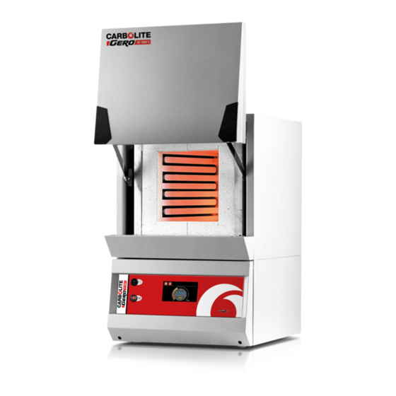
1100°C - 1300°C Chamber Furnaces
types CWF, BWF & RWF
C
ONTENTS
1.0
2.0
3.0
4.0
5.0
6.0
7.0
8.0
9.0
(and overtemperature controller when fitted).
page
1
3
5
6
8
10
12
15
16
MF02
Advertisement
Table of Contents


Need help?
Do you have a question about the CWF and is the answer not in the manual?
Questions and answers
why does the temperature sensor keep flickering on/off