
Subscribe to Our Youtube Channel
Related Manuals for West Marine VHF585 16230534


Summary of Contents for West Marine VHF585 16230534
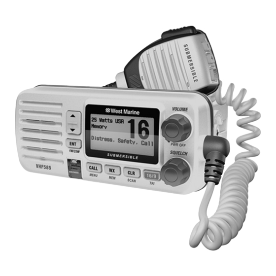
- Page 1 VHF585 CLASS ‘D’ MARINE RADIO MODEL 16230534 (BLACK) / 16230542 (WHITE) Owner’s Manual...
-
Page 2: Making A Voice Distress Call
MAKING A DISTRESS CALL Lift the red cover. Press and hold the DISTRESS button for three seconds. Your radio transmits your boat’ s location every few minutes until you receive a response. NOTE: If the radio displays Enter User MMSI, cancel the automatic distress call and make a normal voice distress call. - Page 3 6. Tell where you are: (what navigational aids or landmarks are near, or read the latitude and longitude from your GPS). 7. State the nature of your distress, e.g. are you sinking, medical emergency, man overboard, on fire, adrift, etc. 8.
-
Page 4: Table Of Contents
TABLE OF CONTENTS Using the Directory Making a Voice Distress Call Inside Front Cover Making DSC Calls Making an automatic distress call Introduction Features Receiving a DSC call Explanation of Terms Test Calls Position Request and Reply Getting Started What’ s included Putting the radio into standby Parts of the Radio Disabling automatic channel switching... -
Page 5: Introduction
INTRODUCTION Features • Complies with JIS8 water-resistant standards, which means the Submersible Design radio can be submerged in 1.5 meter of water for 30 minutes without damage. • Large, dot matrix display • Advanced DSC Class D functions, including Test Calling • Channel select buttons on the microphone • Lets you save channels to memory and monitor them in quick Memory scan mode succession. -
Page 6: Getting Started
Term What it Means Maritime Mobile Service Identity number. A unique, nine-digit number that MMSI identifies you and your boat when making DSC calls. It is also used by the Coast Guard if you send an automated distress call. Station Any DSC radio, whether it’... -
Page 7: Parts Of The Radio
Parts of the Radio Button Press to... Press and hold to... Choose an option on a menu ENT-1W/25W Change the transmit power (see page 16). or to display the GPS data. Move up one channel at a Channel Up Move quickly up the channels. time. -
Page 8: Parts Of The Microphone
Connector/Cable Connects to... For details, see ... External VHF antenna with a male PL259 (SO238) connector and 50 Ω impedance. Connecting the radio (see Antenna connector Minimum 4 ft, 3dB rated antenna for page 39). sailboats, 8 ft, 6 dB rated for power boats. Nominal 13.8 VDC power supply with Connecting the radio (see Power cable pigtail... -
Page 9: Turning On The Radio
Button Press to... Press and hold to... ( + ) Move up one channel at a time. Move quickly up the channels. Move quickly down the ( - ) Move down one channel at a time. channels. 1st press: Go to Channel 16. Go into Triple Watch or Dual 16/9-TRI 2nd press: Go to Channel 9. -
Page 10: How It Works
4. Press ENT-1W/25W. The radio activates the new channel mode and exits the menu. HOW IT WORKS Your radio has three basic modes of operation: Mode What It Does Use It When To Turn it on./off... Monitors a single You want to talk to marine radio channel Normal another station on a... -
Page 11: Normal Mode Operation
Watch Mode What It Does Use It When To Turn it on./off... Change Triple Watch to You want to monitor a Checks for activity on Dual Watch in the setup channel yet maintain Dual channel 16 every two menu, then press and a watch on channel seconds. - Page 12 Using the radio in normal mode • To transmit, press and hold PUSH TO TALK on the microphone. Release the button when you are finished talking. • For the best sound quality, hold the microphone about two inches from your mouth while you’re talking. • Press CHANNEL UP on the radio or the microphone to move up one channel at a time.
- Page 13 Normal mode with Triple and Dual Watch If you activate Triple Watch while operating in normal mode, the radio checks channels 16 and 9 every two seconds; with Dual Watch turned on, the radio only checks channel 16. The radio will not check channels 16 or 9 while you are actively transmitting; it waits until your transmission is finished and then checks the channels.
-
Page 14: Scan Mode
Scan Mode You can save channels into memory and then use scan mode to monitor those channels. When the radio detects a signal on a channel, it pauses on that channel as long as the signal is received; when the transmission stops, the radio will continue scanning. In scan mode, you can get the following information from the display (some indicators will not always be displayed). - Page 15 • When the radio automatically stops on a channel, press CHANNEL UP to leave that channel and resume scanning. • To end the scan, press the microphone’ s PUSH TO TALK, CALL-MEM, or WX-MEM buttons. The radio remains on the last scanned channel. Scan mode with Weather Alert Watch If you activate Weather Alert Watch while operating in scan mode, the radio checks the most recently-used weather channel every seven seconds, then continues scanning the next channel in memory.
-
Page 16: Weather Mode
Scan mode with both Weather Alert and Triple/Dual Watch You can activate Weather Alert Watch and Triple/Dual Watch at the same time. The radio performs both checks at their scheduled time. Weather Mode In cooperation with the FCC, NOAA also uses the weather channels to alert you of other hazards besides weather (child abduction alerts, nuclear, biological, etc.). - Page 17 Weather mode with Weather Alert Watch Because weather mode already monitors the weather channels, you don’t need Weather Alert Watch to check the weather channel every seven seconds. If you activate Weather Alert Watch while operating in weather mode, it operates as a type of “sleep mode”: the radio stays on the weather channel and mutes the speaker.
-
Page 18: Using Your Radio
USING YOUR RADIO To display the radio call menu, press CALL-MENU. To display the radio normal menu, press and hold CALL-MENU. The menu has the following options: Using Your Radio • An arrow on the left side indicates the current selection. • Press CHANNEL UP on the radio or the microphone to move up a line in the menu; if you are at the top line in the menu, the cursor jumps to the bottom of the menu. -
Page 19: Making A Voice Mayday Call
Making a Voice MAYDAY Call (see inside front cover) Setting the Volume Turn the volume knob clockwise to increase the speaker volume; turn it counter-clock- wise to decrease the volume. Setting the Squelch Level The squelch feature reduces the level of static on the speaker by filtering out the back- ground channel noise. -
Page 20: Making A Transmission
Making a Transmission To make a transmission, press and hold the microphone PUSH TO TALK button. Release the PUSH TO TALK button when you’re finished talking to let the other party respond. • To prevent stuck microphone problems or situations where PUSH TO TALK is pushed accidentally, the radio limits your talk time to 5 minutes in a single transmission. If you talk for over 5 minutes continuously, the display shows RELEASE MIC BUTTON. -
Page 21: Choosing Triple Watch Or Dual Watch
Choosing Triple Watch or Dual Watch In Triple Watch mode, the radio briefly checks channels 16 and 9 every two seconds. In Dual Watch mode, the radio checks channel 16 only. Generally, Triple Watch is used in areas where channel 9 is used as a hailing frequency while Dual Watch is used in areas where channel 16 is used for distress and hailing. - Page 22 • For information on the Canadian implementation of FIPS codes, called Canadian Location Codes, see the website of the Meteorological Service of Canada (MSC): http://www.msc.ec.gc.ca/msb/weatheradio/transmitter/index_e.cfm NOTE: If you travel outside the areas you have entered into your radio, you may not hear alerts that affect your new location.
-
Page 23: Changing Display And Sound Options
Changing Display and Sound Options Contrast Your radio display has 10 levels of contrast. To adjust the contrast, press and hold CALL-MENU while the radio is idle. Select System and then Contrast. Use CHANNEL UP and CHANNEL DOWN to change the contrast to your desired level. To restore the default contrast setting, turn the radio off. -
Page 24: Using Digital Selective Calling (Dsc) Features
1. Display the normal menu and choose the Setup sub-menu. 2. Select GPS Setup and then choose Position Set. 3. The GPS manual input screen displays; the fields to be entered blink. The cursor highlights the hour. Use CHANNEL UP and CHANNEL DOWN to set the displayed hours to match coordinated universal time (UTC, also call Greenwich Mean Time and Zulu Time). -
Page 25: Advanced Dsc Features
Advanced DSC Features Your radio supports the following DSC features: Feature Menu Item Function Contact another vessel from Individual Call Individual your directory. Contact all vessels that share Group Call Group your group MMSI code. Broadcast to all vessels within All Ships Call All Ships range (used for safety or... -
Page 26: Entering Mmsi Numbers
• Recreational boaters can obtain an MMSI number from the Boat Owner’ s Association of the U.S. (http://www.boatus.com/mmsi/ or call 800-536-1536) or Sea Tow Services International (http://seatow. com/boating_safety/mmsi.asp) • Commercial boaters need a ship station license to get an MMSI number. For more information, visit the Federal Communications Commission (FCC) website at http:// wireless.fcc.gov/marine/ fctsht14.html. Entering MMSI Numbers Individual or User MMSI Number NOTE: Be sure you have the correct User MMSI number before entering it in the radio. -
Page 27: Group Mmsi Number
5. When the ninth digit is correct, press ENT-1W/25W. The radio displays the new MMSI number and asks you to confirm. NOTE: Be sure you entered the number correctly before confirming the entry. You can only save the user MMSI once. 6. -
Page 28: Using The Directory
Using the Directory The directory lets you store up to 20 MMSI numbers of other stations so you can call them quickly. Follow the steps below to edit the MMSI numbers in your directory: 1. Press CALL-MENU to display the call menu. 2. -
Page 29: Making Dsc Calls
Channel Up Button Channel Down Button Numbers (0 through 9) Lower-case letters (a through z) One blank space Capital letters (A through Z) 8. When the first character is correct, press ENT-1W/25W button. The cursor moves to the next character. Enter the remaining 11 characters of the name. If the name is shorter than 12 characters, press and hold ENT-1W/25W to complete the name entry. - Page 30 Suppose you are coordinating safety for a sailboat race. Before the race starts, you instruct all the racers to enter your group MMSI number into their radios. During the race: • Throughout the race, you use group calling to update the racers on the time, race status, and any course corrections. • A power boat full of spectators comes a little too close to the race path. You use individual calling to contact the power boat and advise them to stay clear of the race.
- Page 31 3. The radio displays the names listed in your directory; use CHANNEL UP and CHANNEL DOWN to choose the directory entry you want to call and press ENT-1W/25W. If you want to call a station that is not in your directory, select Manual. The radio prompts you to enter the MMSI number you want to call.
-
Page 32: Making An Automatic Distress Call
Calling all stations (All-Ships Call) All ships calling contacts all DSC radios within range of your boat. You should only use all ships calling in the event of a Safety warning (such as debris in the water) or to request assistance in an Urgency (any situation where your vessel has a serious problem but is not yet in distress). -
Page 33: Receiving A Dsc Call
3. If no MMSI number has been programmed, the radio prompts you to enter your MMSI number. Canceling an automatic distress call While the radio is waiting for a response, it gives you the option of canceling the call. To cancel the distress call, choose Cancel and press ENT-1W/25W. - Page 34 1. Press CALL-MENU to display the call menu. 2. Select Receive Log. 3. Select Distress to see the last 10 distress call received by the radio. Select Other to see the last 20 normal calls received by the radio, then choose from Individual, Group, or All Ships calls.
-
Page 35: Test Calls
DSC Call Type Receive Log Information Test MMSI (or name), category code. Test Acknowledge MMSI (or name), category code. Pos Reply MMSI (or name), position, time, category code. Pos Request MMSI (or name), category code. Pos Send MMSI (or name), position, time, category code. 6. - Page 36 1. Press CALL-MENU to display the call menu. 2. Select Test. 3. The radio displays the names listed in your directory; use CHANNEL UP and CHANNEL DOWN to choose the directory entry you want to send a test call to and press ENT-1W/25W button.
-
Page 37: Position Request And Reply
Receiving Test Calls When another station sends you a test call, the radio displays the test request screen. • To acknowledge the test call, select Reply. • To reject the test call, select Cancel. Enabling automatic test call reply If you want the radio to automatically reply to all test call, you can enable automatic test call reply. -
Page 38: Enabling Automatic Position Reply
1. Press CALL-MENU to display the call menu. 2. Select DSC Call sub-menu, then select POS Request. 3. The radio displays the names listed in your directory; use CHANNEL UP and CHANNEL DOWN to choose the directory entry you want to contact and press ENT-1W/25W. -
Page 39: Putting The Radio Into Standby
service. Sometimes—for example, in some competitive situations--you may not want other stations to get your position without your manual confirmation 1. Press and hold CALL-MENU to display the normal menu. 2. Select Setup and then POS Reply. 3. Choose Auto and press ENT-1W/25W. The radio will automatically transmit your position when it receives a position request. -
Page 40: Disabling Automatic Channel Switching
1. Display the Call menu. 2. Select Standby to place your radio in standby mode. The radio displays the standby screen, above. 3. To cancel standby and return to the mode your radio was in, press any button. Disabling Automatic Channel Switching If you are involved in a bridge-to-bridge call, you may not want the radio to automatically switch channels when it receives a DSC call. - Page 41 1. Display the normal menu and choose the Setup sub-menu. 2. Select Channel Name. The screen displays the list of channels. 3. Use CHANNEL UP and CHANNEL DOWN to choose the channel you want to change and press ENT-1W/25W. 4. Select Rename to enter a new name for this channel. The radio prompts you to enter a new name for this channel.
-
Page 42: Installing The Hardware
INSTALLING THE HARDWARE Mounting the Radio Your radio can sit at any angle in the mounting bracket so it can easily accommodate the best location. First, determine the best place to mount the radio. For optimum performance, find a location that can: • Properly support the weight of the radio, approximately 2.2 pounds or 1.1 kilograms. -
Page 43: Connecting The Radio
5. Remove the bracket from the radio, and use the mounting hardware to secure the bracket to the mounting surface. 6. Install the radio back into the mounting bracket. Connecting the Radio To operate correctly, your radio requires two electrical connections: • providing it with power from the boat’... -
Page 44: Connecting The Accessory Cable
2. Connect the RED wire of the power cable to the POSITIVE (+) side of your power source. NOTE: To extend the life of the radio, use waterproof tape to seal electrical connections. 3. Install your antenna according to the manufacturer’ s instructions. 4. -
Page 45: Connecting To A Gps Receiver
Connecting to a GPS Receiver If you connect the radio to a GPS receiver, the radio can automatically transmit your current position during an automated distress call or during a normal DSC call. Your radio supports a standard NMEA0183 input from a GPS receiver. Follow the steps below to connect your radio to your GPS receiver: 1. -
Page 46: Connecting To A Chartplotter
After 4 hours, the audible alert sounds again if no coordinates are received and the GPS is connected. After 23.5 hours, the radio deleted the current coordinates and displays Input GPS. See page 19 to manually set the GPS coordinates. Configuring the GPS If the radio is receiving valid GPS data, it will automatically set the clock to your local time based on the GPS location. -
Page 47: Connecting To An External Speaker
plotter. When it receives another boat’ s position data in a DSC call, the radio sends the position data to the chartplotter so you can see the location: 1. Connect the ORANGE wire of the accessory cable to the NEGATIVE (-) wire of your chartplotter’... -
Page 48: Maintenance And Troubleshooting
MAINTENANCE AND TROUBLESHOOTING Due to its rugged design, your radio requires very little maintenance. However, it is a precision electronic instrument, so you should follow a few precautions: • If the antenna has been damaged, you should not transmit except in the case of an emergency. A defective antenna may cause damage to your radio. • You are responsible for continued FCC technical compliance of your radio. -
Page 49: Engine Noise Suppression
Problem Things to Try Adjust the backlight brightness level. The display is too bright at Turn off the radio; hold CALL-MENU button and turn it night. back on (see page 19). I can’t see any words on the Reset the radio back to the default brightness level: turn off display. - Page 50 wires, antenna lead, and accessory cables should be routed away from the engine and engine compartment, and from power cabling carrying high currents. In severe cases of noise interference, it may be necessary to install a noise suppression kit. Contact the dealer where you purchased the radio for more information.
-
Page 51: Specifications
SPECIFICATIONS All speficifations are subject to change without notice. Radio Specifications General Controls Volume-Pwr, Squelch Transmit power, Scan mode, Triple Watch mode, Battery High, Battery Status Indicators low, USA, CAN, INT, Alert, Memory, GPS, Message, Weather band, GPS status and Channel Display Display LCD (Full Dot Matrix) ENT-1W/25W, Channel UP, Channel DOWN, CALL-MENU,... - Page 52 General Less than 8% with 3 kHz deviation with 1000 Hz modulating Audio Distortion frequency Spurious Suppression –45 dBm @ Hi, –55 dBm @ Lo Output Power Built-in automatic level control (ALC) Stabilization Frequency Range 156 to 158 MHz Frequency Stability ±10 ppm @ –20°C to + 50°C Receiver Frequency Range...
-
Page 53: Reference Tables
REFERENCE TABLES NOTE: This radio does not support AIS channels. Channel Descriptions and What They Mean The table below lists the display name or channel description used in the following tables and what each description means. Channel name/description Used for DISTRESS SAFETY AND CALLING primarily emergency messages and distress calls safety messages from one ship to another, or from a... -
Page 54: Us Marine Channels And Frequencies
US Marine Channels and Frequencies Ch No. RX Freq TX Freq Status Name on display 156.0500 156.0500 Simplex Vessel traffic system/Commercial 156.2500 156.2500 Simplex Vessel traffic system/Commercial 156.3000 156.3000 Simplex Inter-ship safety 156.3500 156.3500 Simplex Commercial 156.4000 156.4000 Simplex Commercial 156.4500 156.4500 Simplex... - Page 55 Ch No. RX Freq TX Freq Status Name on display 156.3750 156.3750 Simplex, 1W Bridge to bridge 156.4250 156.4250 Simplex Non commercial 156.4750 156.4750 Simplex Non commercial (156.5250 156.5250) DSC Only 156.5750 156.5750 Simplex Non commercial 156.6250 156.6250 Simplex Non commercial (ship-ship) 156.6750 156.6750 Simplex...
-
Page 56: Canadian Marine Channels And Frequencies
Canadian Marine Channels and Frequencies Ch No. RX Freq TX Freq Status Name on display 160.6500 156.0500 Duplex Marine operator 160.7000 156.1000 Duplex Marine operator 160.7500 156.1500 Duplex Marine operator 156.2000 156.2000 Simplex Canadian coast guard 156.2500 156.2500 Simplex Vessel traffic system 156.3000 156.3000 Simplex... - Page 57 Ch No. RX Freq TX Freq Status Name on display 161.9500 157.3500 Duplex Marine operator 162.0000 157.4000 Duplex Marine operator 160.6250 156.0250 Duplex Marine operator 156.0750 156.0750 Simplex Canadian coast guard 156.1250 156.1250 Simplex Canadian coast guard 156.1750 156.1750 Simplex Port operation 160.8250 156.2250...
-
Page 58: International Marine Channels And Frequencies
Ch No. RX Freq TX Freq Status Name on display 157.1750 157.1750 Simplex Canadian coast guard 161.8250 157.2250 Duplex Marine operator 161.8750 157.2750 Duplex Marine operator 161.9250 157.3250 Duplex Marine operator 157.3750 157.3750 Simplex Port operation 157.4250 157.4250 Simplex Port operation International Marine Channels and Frequencies Ch No. - Page 59 Ch No. RX Freq TX Freq Status Name on display 161.6000 157.0000 Duplex Port operation 161.6500 157.0500 Duplex Port operation 161.7000 157.1000 Duplex Port operation 161.7500 157.1500 Duplex Marine operator 161.8000 157.2000 Duplex Marine operator 161.8500 157.2500 Duplex Marine operator 161.9000 157.3000 Duplex...
-
Page 60: Weather Channels And Frequencies (Us, Can, And Int)
Ch No. RX Freq TX Freq Status Name on display 161.6750 157.0750 Duplex Port operation 161.7250 157.1250 Duplex Port operation 161.7750 157.1750 Duplex Port operation 161.8250 157.2250 Duplex Marine operator 161.8750 157.2750 Duplex Marine operator 161.9250 157.3250 Duplex Marine operator 157.3750 157.3750 Simplex... - Page 61 • An EMERGENCY is an event that, by itself, would not kill or injure or do property damage, but indirectly may cause other things to happen that result in a hazard. For example, a major power or telephone loss in a large city alone is not a direct hazard, but disruption to other critical services could create a variety of conditions that could directly threaten public safety.
- Page 62 Event SAME Code Type Tropical Storm Warning Warning Tsunami Watch Watch Tsunami Warning Warning Winter Storm Watch Watch Winter Storm Warning Warning National Information Center Test Avalanche Watch Watch Avalanche Warning Warning Child Abduction Emergency Emergency Civil Danger Warning Warning Civil Emergency Message Emergency Earthquake Warning...
-
Page 63: No Response Event Code
Event SAME Code Type Dam Break Watch Warning Contagious Disease Warning Warning Emergency Action Notification Warning Emergency Action Termination Statement Evacuation Watch Watch Flood Contamination Warning Warning Flash Freeze Warning Warning Iceberg Warning Warning Industrial Fire Warning Warning Landslide Warning Warning National Audible Test Test... - Page 64 NMEA Input If you have difficulty getting your radio to receive data from your GPS receiver, check the device’ s configuration. It should be set to the following parameters: Baud rate 4800 bps Data bits Parity None Stop bits Data amplitude Over 3.0 V Drive capability Over 10 mA...
-
Page 65: Nmea Output
NMEA Output When the radio receives a DSC call (Distress, Position Reply, or Position Send), it outputs a DSC/DSE sentence from the NMEA output port. NOTE: When the radio receives a distress call, it outputs a sentence in the following format: • $CDDSC,12,3081234000,,07,00,0354013946,0657,,,S,E*6D • $CDDSE,1,1,A,3081234000,00,60875646*13 VHF585 RADIO... -
Page 66: Regulations And Safety Warnings
This device complies with Part 15 of the FCC Rules. Operation is subject to the condition that this device does not cause harmful interference. Unauthorized changes or modifications to this equipment may void compliance with the FCC Rules. Any change or modify cation must be approved in writing by West Marine. VHF585 RADIO 1-800-BOATING... -
Page 67: Lead Warning
The cords on this product and/or accessories contain lead, a chemical known to the State of California to cause birth defects or other reproductive harm. Wash hands after handling. West Marine works to reduce lead content in our PVC coated cords in our products and accessories. -
Page 68: Three Year Limited Warranty Statement
This Limited Warranty is Void outside the United States of America and Canada. What Does This Limited Warranty Cover? West Marine warrants to the original retail purchaser of the West Marine product, where the purchase is made in the United States or Canada, that for thirty-six (36) months from date of original retail purchase said product will be free from defects in materials and craftsmanship with only the limitations or exclusions set out below. - Page 69 What Will West Marine Do? During the Limited Warranty Term, if the product you return to us proves to be defective in materials...
- Page 70 Refurbished parts and systems are parts or systems that have been returned to West Marine, some of which were never used by a customer. Replacement parts and systems are covered for the remaining time left in the Limited Warranty Term for the product you bought (whatever time remains in the twelve months since purchase).
-
Page 71: Notes
NOTES VHF585 RADIO 1-800-BOATING... - Page 72 www.westmarine.com Printed in Vietnam U01UT652ZZA(0)
Need help?
Do you have a question about the VHF585 16230534 and is the answer not in the manual?
Questions and answers