Table of Contents
Advertisement
Advertisement
Table of Contents

Related Manuals for Absima CR4T


Summary of Contents for Absima CR4T
- Page 1 CR4T Version 01/13 2,4Ghz Radio System...
-
Page 2: Table Of Contents
Index Page 1. Introduction ................................4 2. Correct use................................5 3. Product description.............................5 4. Scope of delivery ............................5 5. Symbols explanation ............................6 6. Safety instructions..............................6 a) General................................6 b) Operation ................................7 7. Battery details ..........................8 8 Charge batteries ..............................9 9. - Page 3 Page h) Throttle neutral.............................25 i) Throttle exponential ............................26 j) Throttle curve ..............................26 k) A.B.S................................27 l) Throttle speed ...............................28 m) Throttle middle position ..........................29 n) Throttle idle up .............................29 o) Engine cut ..............................30 p) Boat mode ..............................30 q) Brake mixing ..............................31 r) Mixes ................................31 s) Display servos .............................33 t) Race timer ..............................33...
-
Page 4: Introduction
Keep these instructions for future reference! All company names and products are trademarks of their respective owners. All rights reserved. For technical questions, contact: Tel.: +49 (0)911/650841 30 Fax: +49 (0)911/650841 40 E-Mail: info@absima.com to Th. 8.00-17.00 o´clock 8.00-15.00 o´clock... -
Page 5: Correct Use
Sehr g sonder 2. Correct use aufmer The 4 channel radio control is designed exclusively for the private use in model range with the associated operating a) Al hours. Stand for a industrial use, for example the control of machines or installations, this system is not suitable. A another use, described as previously, may damage the product. -
Page 6: Symbols Explanation
5. Symbols explanation The icon with an exclamation point indicates a particular risk associated with handling, operation and control. The "arrow" icon puts everyone in special tips and operating information. 6. Safety instructions Damages caused by non-compliance with these instructions will invalidate the warranty / guarantee. -
Page 7: B) Operation
• Check that they are before putting into operation the reliability of your model and the remote control system. Look out for any signs of damage, such as faulty connections or damaged cables. All moving parts have to function smoothly, but no play in the main in storage have. •... -
Page 8: Battery Details
7. Battery details • Batteries / rechargeable batteries out of reach of children. • Don´t leave batteries / rechargeable batteries open, there is a risk that can be swallowed by children or pets. In such a case, contact a doctor immediately. •... -
Page 9: Charge Batteries
Charge batteries Required for the remote control battery is normally upon delivery empty and needs to be recharged. Please note: Before a battery that offers maximum performance, several complete discharge and recharge cycles are required. Discharge the batteries at regular intervals, as may occur when multiple charging a "half-full" batteries for so-called memory effect. -
Page 10: Radio Controls
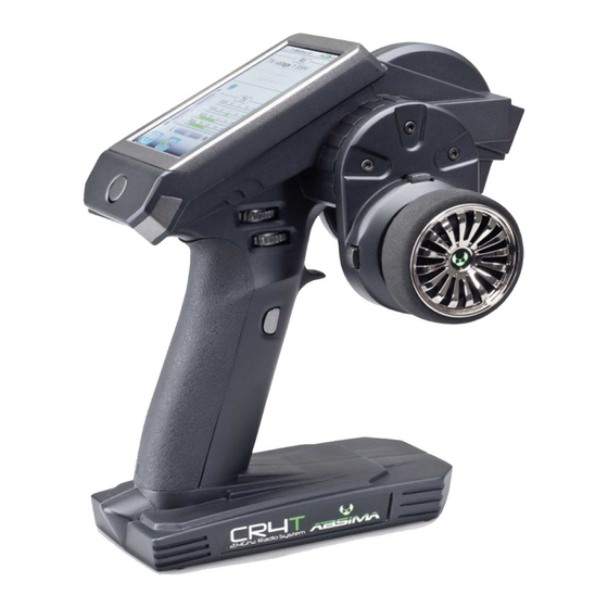
9. Radio controls 1. LCD-Touchscreen-Display 2. TR1 (exponential function throttle/brake) 3. TR4 (exponential function steering) 4. TR5 (channel 3) 5. SW1 (channel 3) 6. SW2 (channel 4) 7. POWER (on/off) 8. SW3 (A.B.S.) 9. TR3 (trim throttle/brake) 10. Steering wheel 11. -
Page 11: Commissioning Of Radio
10. Commessioning of the radio Later in the guide, the numbers in the text always on the adjacent image or the images within the section. Cross-references to other pictures are given with the corresponding image number. a) Insert the battery The battery cover (1) is located on the bottom of the transmitter. -
Page 12: C) Test And Setting The Digital Trim
c) Test and setting the digital trim Before operate adjustments to their model or start programming your product, you need to make sure that the digital trim for the steering and driving function is in the central position (0). Center position of the steering function With the trim button (TR2) for the steering function, the center position for the steering servo will be adjusted (ST). -
Page 13: Commissioning Of Receiver
11. Commissioning of the receiver a) Receiver connection The receiver provides connectivity for up to four servos (CH1, CH2, CH3, CH4) and a receiver battery (B/VCC). Always pay attention the correct polarity of the connector when you connect the servos. Plug contact for the pulse line should be on the inner (left) pin connected (depending on the manufacturer of yellow, white or orange). -
Page 14: B) Install The Receiver
Require in addition to the steering servo on receiver output "CH1" and the throttle servo/speed controller receiver output "CH2" can be connected additional a servo to receiver output "CH3". This servo takes at the push of a button functions on the transmitter. In an electric model with mechanical speed controller is for the power supply of the receiver a battery box or a separate receiver battery required. -
Page 15: D) Binding Function
d) Binding function Thus, the transmitter and receiver can communicate with each other, you need through the same digital code are bound together. When delivered, the transmitter and receiver already matched and can be used immediately. The renewal of the binding function is primarily required for a transmitter or receiver changes or to correct faults. -
Page 16: Test The Steering-, Drive-, And Shift Function
13. Testing the steering-,drive-, and shift function Place the model on a suitable base (wooden block or similar) to test the steering and handling functions. The wheels should rotate freely. a) Test the steering function For the testing turn on the transmitter and the receiver. If you did everything correctly connected and installed, the steering should respond to the rotary motion of the steering wheel. -
Page 17: B) Test The Drive Function
b) Test the drive function To accelerate the model you have to pull the throttle/brake trigger in the direction of the handle. To decelerate the model you have to push the throttle/ brake trigger in front of the handle. If the control direction exactly opposite to the direction of the transmitter control you can easily re-program. -
Page 18: Programming The Radio Control
14. Programming the radio control a) Programming the radio control This product offers you the opportunity to tune the ride, steering and control functions of your model individually and save the values stored permanently. Only an adjusted to the rider's model offers maximum driving pleasure. The command of the product is carried out via the touch screen display. -
Page 19: B) Symbol Explanation
b) Icon explanation Icon Main menu This icon will take you to the main menu, where you can program your product individual. Back This icon allows you to return back to the previous menu. Activate/ With these icons you activate or deactivate Deactivate your customizations. -
Page 20: Adjustments In The Main Menu
15. Adjustments in the main menu a) Adjustments main menu Turn on the transmitter and select the main menu. The following setting options are at your disposal: Picture 11... -
Page 21: B) Reverse
b) Reverse With this function, you can change the direction of servo rotation of all four channels (CH1 to CH4). Depending on the installation location and linkages in the model, it may be necessary to change the direction of rotation of the servo. Tap therfor the controller to change the servo direction of the desired channel from normal (NOR) to Reverse (REV). -
Page 22: C) End Points
c) End points Picture 13 This feature allows you to specify how large can the maximum allowable deflection for the steering, gas or auxiliary power is on each side. This function is normally used to protect the servos at full deflection before the mechanical abutment set in. -
Page 23: D) Subtrims
d) Subtrims Picture 14 This feature allows an individual adjustment of the center position of the driving and steering servo. A slight pull to the left of the model can be compensated/corrected with the help of trim. Thus the correct straight is ensured when the steering wheel is on the transmitter in the central position. -
Page 24: E) Steering Exponential
e) Steering exponential This feature allows you to influence the steering sensitivity. Thereby the linear distance between the transmitter control and servo is changed in a non-linear (exponential) way. A fine control to the neutral position is possible. The maximum control path is not changed. -
Page 25: G) Steering Mix
g) Steering mix This function allows you to set four different steering modes on the model. „Front side“: Only the front wheel steering is controlled. „Rear side“: Only the rear wheel steering is controlled. „Same Phase“: Front and rear wheels are equal sorted controlled. „Rev. -
Page 26: I) Throttle Exponential
i) Throttle exponential This feature allows you to influence the sensitivity of the throttle/brake servos. Thereby the linear distance between the transmitter control and servo is changed in a non-linear (exponential) way. A fine control to the neutral position is possible. The maximum control path is not changed. -
Page 27: K) A.b.s
k) A.B.S. Picture 21 This feature allows the wheels from locking during braking by automatically pulsing (opening and closing the brakes) to prevent. Thus it is possible to retain the control over the model even during heavy braking. „Brake return“: This determines how far the brake is released with each impulse. -
Page 28: L) Throttle Speed
„Steering mix“: Here can be coupled the activation of the "ABS" on the steering angle. A positive value (N) is activated the "ABS" only, if they are within the range of steering to the neutral position. A negative value (E) is activated the "ABS" only, when the steering system is located outside the area around the neutral position. -
Page 29: M) Throttle Middle Position
m) Throttle middle position This feature allows you to adjust the center servo horn between accelerator and brake operation. This may be necessary in particular when the servo-way between the gas and brake operation are not identical. Move the controller to the right or left to adjust the value according to your wishes.Tap the button "back"... -
Page 30: O) Engine Cut
o) Engine cut With this function, the position of the throttle/brake trigger from the radio control is ignored and the throttle/brake servo set to a predefined position. Select the button "Activate". Move the controller to the right or left to adjust the value according to your wishes. Select the button "activate"... -
Page 31: Q) Brake Mixing
q) Brake mixing This feature allows you to control the brakes via two or three independent servos. Channels 3 (CH3), or 4 (CH4) can be used as the slave channels for throttle/brake servo, whereby only the brake function has an influence on the slave channels. After activating one of the two channels, can be adjusted for this channel the ABS and the exponential function of the individually throttle/brake servo. - Page 32 Picture 29 „Master channel“: Here the master channel is selected. „Slave channel“: Here the slave channel is selected. „Low side mix“: Here the influence of the left master channel is mixed on the slave channel. A value of 50% shares of the impact on both channels.
-
Page 33: S) Display Servos
s) Display servos This feature shows you in real time the position of all four servo arms. Using the "Test" button to investigating whether the mechanism in the model is working properly. Therefor the servo arms moved slowly between its end points back and forth. Picture 30 t) Race timer This feature allows the measurement of time in four... -
Page 34: U) Key Function
The timing continues even when the set timing is counted. In this case, the product will automatically switch to the mode "up timer". „Lap timer“: This mode allows you to save a certain lap time. Tap the "Start" button to start the timer. Then tap the button "Lap" to save a lap time. To stop the timer, tap the "Reset" button. -
Page 35: V) Models
v) Models This feature allows you to save from 20 model-specific profiles. „Name“: Enter the name of the profile. Tap the button "back" in order to save the changes and return to the menu. „Select model“: Choose from the list the desired profile. Tap the button "back" in order to activate the selected profile and to get back into the menu. - Page 36 w) RX setup This feature allows you to program the receiver. The following setting options are at your disposal: „Bind with a receiver“: Select this when the radio control will be connected to a receiver again. „RX battery monitor“: This feature displays the following information of the receiver battery: „External sensor“: Activate this feature if you use an external sensor.
- Page 37 „Throttle“ activate: Tap the button "activate / deactivate". Pull the throttle/brake trigger forward or backward and hold the desired position. Tap the button "back" in order to save the changes and return to the menu. „Throttle“ deactivate: Select the function "throttle". Tap the button "activate / deactivate" to deactivate the set value. „Display sensors“: his feature displays all the information about all connected sensors.
-
Page 38: X) System
x) System This menu allows different settings for your product. „Backlight timeout“: You can set the duration of the backlight of the LCD when it is not touched. „Backlight“: This adjusts the brightness of the backlight for the LCD display. A higher value makes for better recognition on the LCD screen, and also for a rapid discharge of the battery. -
Page 39: Service And Support
Service and support Externally, the remote control can be cleaned with a soft, dry cloth or brush. Do not use abrasive cleaners or chemical solvents, as the surface of the housing could be damaged. 17. Disposal a) General Later in the guide, the numbers in the text always on the adjacent image or the images within the section. Cross-references to other pictures are given with the corresponding image number. -
Page 40: Elimination Of Errors
18. Elimination of errors Although this remote control system was built using state of the art, it can still cause a malfunction or fault. For this reason, we want to show you how any disturbances can eliminate. Problem Corrective Radio control has no function •... -
Page 41: Technical Specifications
Power supply:..........4,0V - 6,5V 20. Declaration of conformity (DOC) The manufacturer hereby declares that this product complies with the essential requirements and other relevant provisions of directive 1999/5/EC. The declaration of conformity for this product can be found at www.absima.com. - Page 42 Imprint This manual is published by the company Absima GmbH, Gibitzenhofstr. 127A, D-90433 Nuremberg (www.absima.com). All rights reserved including translation. Reproduction by any method, for example Photocopying, microfilming or storage in electronic data processing systems, need to the written permission of the publisher. Reproduction in whole or in part is illegal.
Need help?
Do you have a question about the CR4T and is the answer not in the manual?
Questions and answers