Table of Contents
Advertisement
Quick Links
Advertisement
Table of Contents

Related Manuals for Pfaff 1193


Summary of Contents for Pfaff 1193
- Page 1 1193 1194 Service manual 296-12-18 162 Betriebsanleitung engl. 09.98...
- Page 2 This Instruction manual is valid for all models and subclasses listed in the chapter „Specifications“. The reprinting, copying or translation of PFAFF Instruction Manuals, whether in whole or in part, is only permitted with our previous permission and with written reference to the source.
-
Page 3: Table Of Contents
Contents Contents ................Chapter - Page Safety ........................1 - 1 Directives ........................1 - 1 General notes on safety ..................... 1 - 1 Safety symbols ......................1 - 2 Important notes for the user ..................1 - 2 Operating and technical staff ..................1 - 3 .05.01 Operating staff ...................... -
Page 4: Contents
Needle thread tension release (on the PFAFF 1194) ..........11 - 13 Thread check spring and thread regulator (on the PFAFF 1193) ......11 - 14 Thread check spring and thread regulator (on the PFAFF 1194) ......11 - 15 Setting the knee lever .................... -
Page 5: Safety
Safety Safety Regulations This machine is constructed in accordance with the European regulations indicated in the conformity and manufacturer's declarations. In addition to this instruction manual, please also observe all generally accepted, statutory and other legal requirements, including those of the user's country, and the applicable pol- lution control regulations! The valid regulations of the regional social insurance society for occupational accidents or other supervisory authorities are to be strictly adhered to! -
Page 6: Safety Symbols
The user must ensure that none of the safety devices are removed nor put out of work- ing order. The user must ensure that only authorized persons operate and work on the machine. For further information please refer to your PFAFF agency. 1 - 2... -
Page 7: Notes For Operating And Technical Staff
Safety Notes for operating and technical staff Operating staff .05.01 Operating staff are the persons responsible for setting up, operating and cleaning the mach-ine and for removing any disturbances in the sewing area. The operating staff are obliged to observe the following points, and must: always observe the notes on safety in this instruction manual! avoid using any working methods which adversely effect the safety of the machine! avoid wearing loose-fitting clothing or jewelry such as necklaces or rings! -
Page 8: Danger Warnings
Safety Danger warnings A working area of 1 metre is to be kept free both in front of and behind the machine while it is in operation, so that it is always easily accessible. Never reach into the sewing area while sewing! Danger of injury by the needle! Never leave objects on the table while adjusting the machine settings! Objects can become trapped or be hurled out! Danger of injury by flying objects!! Fig. -
Page 9: Proper Use
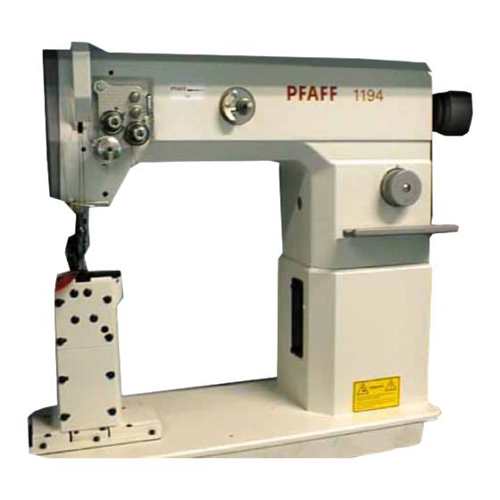
Proper use Proper use The PFAFF 1193 is a single-needle lockstitch post-bed sewing machine with bottom feed and roller presser. The PFAFF 1194 is a two-needle lockstitch post-bed sewing machine with bottom feed and roller presser. The machines are used for producing lockstitch seams in industry. -
Page 10: Specifications
At a speed of 2000 spm: ..................78 dB(A) Noise measurement in accordance with DIN 45 635-48-A-1 Net weight of the sewing head: PFAFF 1193 ....................approx. 47 kg PFAFF 1194 ....................approx. 49 kg Subject to technical alterations Dependent on the material, operating cycle and stitch length... -
Page 11: Disposal Of Machine
Disposal of Machine Disposal of Machine Proper disposal of the machine is the responsibility of the customer. The materials used for the machine are steel, aluminium, brass and various plastic mat- erials. The electrical equipment comprises plastic materials and copper. The machine is to be disposed of according to the locally valid pollution control regula- tions;... -
Page 12: Transportation, Packing And Storage
Transportation, packing and storage Transportation, packing and storage Transportation to customer's premises Within the Federal Republic of Germany, complete machines (with table and motor) are delivered without packing. Machines without table (only sewing heads) and machines intended for exports are packed. Transportation inside the customer's premises The manufacturer cannot be made liable for transportation inside the customer's premises nor to other operating locations. -
Page 13: Explanation Of Symbols
Explanation of symbols Explanation of symbols In this instruction manual, work to be carried out or important information is accentuated by simbols. These symbols have the following meanings: Note, information Cleaning, care Lubrication Maintenance, repairs, adjustment, service work (only to be carried out by technical staff) 6 - 1... -
Page 14: Controls
Controls Controls On/off switch Turn the machine on and off by turning the on/off switch 1. The switch in the illustration can be found on machines with Quick motors. When other motors are used, other switches may be fitted. Fig. 7 - 01 Pedal 0 = Neutral position 1 = Sew... -
Page 15: Lever For Lifting The Roller Presser
Controls Lever for lifting the roller presser The roller presser is lifted by raising lever 1. Fig. 7 - 03 Knob for adjusting the stitch length The stitch length can be adjusting by applying pressure to the adjustment knob 1, while at the same time turning it as required. -
Page 16: Reverse Key
Controls Reverse key For reverse sewing key 1 must be pressed. Fig. 7 - 05 Knee lever The roller presser is lifted by moving lever 1 in the direction of the arrow. Fig. 7 - 06 7 - 3... -
Page 17: Installation And Commissioning
Installation and commissioning Installation and commisioning The machine must only be installed and comissioned by qualified personnel! All relevant safety regulations are to be observed! If the machine is delivered without a table, it must be ensured that the stand and the table top which you intend to use can hold the weight of the machine. -
Page 18: Adjusting The V-Belt Tension
Installation and commissioning Adjusting the V-belt tension .01.02 Loosen nuts 1. Tighten the V-belt with belt take-up hangar 2. 2 cm Tighten nuts 1. Fig. 8-02 shows an illustration of a Quick motor. If another motor is used, proceed as described in the motor’s instruction manual. -
Page 19: Fitting The Lower V-Belt Guard
Installation and commissioning Fitting the lower V-belt guard .01.04 Align belt guard 1 in such a way that both the motor pulley and the V-belt run freely. Tighten screws 2. Fig. 8-04 shows an illustration of a Quick motor. If another motor is used, proceed as described in the motor’s instruction manual. -
Page 20: Commissioning
Installation and commissioning Commissioning Check the machine, in particular the electrical leads, for any damage. Clean the machine thoroughly, also see Chapter 10 Care and Maintenance. Have mechanics ensure that the machine’s motor can be operated with the available electricity supply and that it is connected correctly. If not, the machine must not be operated under any circumstances. -
Page 21: Setting Up
Before all preparation work, the machine is to be switched off at the on/off switch or disconnected from the electricity supply by removing the plug from the mains! Inserting the needles in the PFAFF 1193 Turn the machine off! Danger of injury if the machine... -
Page 22: Inserting The Needle (On The Pfaff 1194)
Rüsten Inserting the needles in the PFAFF 1194 Turn the machine off! Danger of injury if the machine is started accidentally! Use only system 134 134 needles. Raise the roller presser and swing it out. Raise the needle bar as far as possible. -
Page 23: Winding The Bobbin Thread, Adjusting The Thread Tension
Rüsten Winding the bobbin thread, adjusting the thread tension Fig. 9 - 03 Place an empty bobbin 1 onto bobbin spindle 2. Thread the bobbin in accordance with Fig. 9-03 and wind it clockwise around the bobbin 1 a few times. Engage on the bobbin winder by pressing bobbin winder shaft 2 and lever 3 at the same time. -
Page 24: Changing The Bobbin / Threading The Bobbin Thread
Rüsten Changing the bobbin / threading the bobbin thread Turn the machine off! Danger of injury if the machine is started accidentally! Raise take-up lever as far as possible. Open the post cap, raise latch 1 and remove bobbin. Insert the full bobbin into the hook drive in such a way that the bobbin rotates in the direction of the arrow when the thread is pulled. -
Page 25: Threading The Needle Thread / Adjusting The Needle Thread Tension (On The Pfaff 1193)
Rüsten Threading the needle thread / adjusting the needle thread tension (on the PFAFF 1193) Fig. 9 - 06 Turn the machine off! Danger of injury if the machine is started accidentally! Thread the needle thread as shown in Fig. 9-06. -
Page 26: Threading The Needle Thread / Adjusting The Needle Thread Tension (On The Pfaff 1194)
Rüsten Threading the needle thread / adjusting the needle thread tension (on the PFAFF 1194) Fig. 9 - 07 Turn the machine off! Danger of injury if the machine is started accidentally! Thread the needle thread as shown in Fig. 9-07. -
Page 27: Care And Maintenance
Care and maintenance Care and maintenance Cleaning and maintenance intervals Clean the hook compartment ....daily, several times if in continuous operation Lubricate the hook .................. daily, before use Clean the hook ....................once a week Lubricate the post ..................twice a week Grease the bevel gears .................. -
Page 28: Lubricating The Post
Only use oil with a mean viscosity of 10.0 mm /s at 40° C and a density of 0.847 g/cm 15° C! We recommend PFAFF sewing machine oil, order-No. 280-1-120 105. Fig. 10 - 02 Lubricating the hook Insert 1 - 2 drops... -
Page 29: Greasing The Bevel Gears
Tilt the machine backwards onto the support. Apply new grease to the bevel gears 1 and 2 once a year. We recommend PFAFF sodium grease with a dripping point of approx. 150°C, order no. 280-1-120-243. Fig. 10 - 04 10 - 3... -
Page 30: Adjustment
Adjustment Adjustment No adjustable clamp may be fastened to the needle bar of the PFAFF 1193 and the PFAFF 1194. This could cause damage to the special surface of the needle bar. The illustrations in this section show the PFAFF 1193 single-needle machine. -
Page 31: Control And Adjusting Aids
Adjustment Control and adjusting aids With the help of the adjustment pin 1 (Part no. 13-033 346-05) the required needle rise position, needle bar 1.8 mm after BDC, can be fixed. Fig. 11 - 01 Turn the balance wheel until the needle bar is approximately in the required position. Insert adjustment pin 1 into the hole. -
Page 32: Pre-Adjusting The Needle Height
Adjustment Pre-adjusting the needle height Requirement With the needle bar at BDC, the distance between the needle bar 1 and the needle plate must be 15 mm. Fig. 11 - 02 Bring needle bar 1 to BDC. Position needle bar 1 (screw 2) in accordance with the requirement, without twisting it. 11 - 3... -
Page 33: Setting The Feed Dog At Neutral Position
Adjustment Setting the feed dog at the neutral position Requirement With the stitch length set at "0", the cranks 1 and 3 must be in alignment, and there should be no driving motion of the feed dog when the balance wheel is turned. Fig. -
Page 34: Lifting Motion Of The Feed Dog
Adjustment Lifting motion of the feed dog Requirement With the stich length set at "0" and the needle bar at its TDC 1. the feed dog must be at its top point of reversal, 2. the control cam 3 must be touching the feed lifting eccentric 1 and 3. -
Page 35: Feed Dog Height
Adjustment Feed dog height Requirement With the switch length set at "0" and the needle bar at its TDC, the feed dog should 1. be positioned in the centre of the needle plate cutout and 2. protrude 0.8 - 1.0 mm from the needle plate. Fig. -
Page 36: Driving Motion Of The Feed Dog
Adjustment Driving motion of the feed dog Requirement With the longest stitch set and the needle bar positioned at TDC, the feed dog should not move when the reverse-feed lever 3 is operated. Fig. 11 - 06 Set the longest stitch. Bring the needle bar to its TDC. -
Page 37: Centering The Needle In The Needle Hole
Adjustment Centering the needle in the needle hole Requirement The needle should enter the needle hole exactly in the centre. Fig. 11 - 07 Position the needle directly above the needle hole. Loosen screws 1, 2 and 3. Position the needle bar frame 4 in accordance with the requirement requirement requirement requirement... -
Page 38: Hook Shaft Bearing And Gearwheel Backlash
Adjustment Hook shaft bearing and gearwheel backlash Requirement 1. The front edge of the hook shaft bearing should have a clearance of 13 mm to the cast-iron edge. 2. There should be a slight backlash between the gearwheels 3 and 5. Fig. -
Page 39: Needle Rise, Hook-To-Needle Clearance, Needle Height And Needle Guard
Adjustment Needle rise, hook-to-needle clearance, needle height and needle guard Requirement With the needle bar positioned 1.8 mm after BDC 1. The hook point must be at the needle centre position and clear the needle groove by 0.05 - 0.10 mm. 2. -
Page 40: Bobbin-Case Opener
Adjustment Bobbin-case opener Requirement The needle thread must not be clamped between the bobbin-case opener 1 and the bobbin- case 3 3 3 3 3 , nor may it be clamped between projection 4 and the retaining trip of the needle plate. Fig. -
Page 41: Needle Thread Tension Release (On The Pfaff 1193)
Adjustment Needle thread tension release (on the PFAFF 1193) Requirement With the presser bar lifter 1 1 1 1 1 raised, the tension discs 4 4 4 4 4 must be at least 0.5 mm 0.5 mm 0.5 mm 0.5 mm 0.5 mm apart. -
Page 42: Needle Thread Tension Release (On The Pfaff 1194)
Adjustment Needle thread tension release (on the PFAFF 1194) Requirement With the presser bar lifter 1 raised, the tension discs 4 must be at least 0.5 mm apart. 0,5 mm Fig. 11 - 12 Align pressure plate 1 behind tension carrier plate 2 in accordance with the requirement. -
Page 43: Thread Check Spring And Thread Regulator (On The Pfaff 1193)
Adjustment Thread check spring and thread regulator (on the PFAFF 1193) Requirement 1. The motion of the thread check spring should have ceased when the needle point enters the material (spring stroke approximately 7 mm 7 mm 7 mm 7 mm 7 mm). -
Page 44: Thread Check Spring And Thread Regulator (On The Pfaff 1194)
Adjustment Thread check spring and thread regulator (on the PFAFF 1194) Requirement The motion of the thread check spring 1 should have ceased when the needle points enter the material ( = approx. 7 mm spring stroke). Fig. 11 - 14 Turn screw 2 (screw 3) to adjust the tension of thread check spring 1. -
Page 45: Setting The Knee Lever
Adjustment Setting the knee lever Requirement 1. When the knee lever is in its resting position, axis 5 5 5 5 5 should be parallel to the bedplate. 2. When the roller presser rests on the needle plate, the presser bar lifting lever 6 6 6 6 6 should touch the safety ring 8 8 8 8 8 and clear the lifting piece 7 7 7 7 7 by approximately 1 mm 1 mm 1 mm... -
Page 46: Knee Lever Stop
Adjustment Knee lever stop Requirement When the knee lever has been moved as far as possible, the roller presser should rise approximately 9 mm above the needle plate, and lever 3 should swing down automatically. Fig. 11 - 16 Schraube 1 ( Mutter 2 ) entsprechend der Requirement verdrehen. 11 - 17... -
Page 47: Bobbin Winder
Adjustment Bobbin winder Requirement 1. When the bobbin winder is switched on, the drive wheel 1 must engage reliably. 2. When the bobbin winder is switched off, the friction wheel 5 must not touch the drive wheel 1. 3. The bobbin winder must switch off automatically when the thread level is approx. 1 mm from the edge of the bobbin. -
Page 48: Limiting The Stitch Length
Adjustment Limiting the stitch length The maximum stitch length can be limited mechanically. Fig. 11 - 18 Set the required maximum stitch length on the adjustment knob 1. Move crank 2 (screws 3) from above to rest on stop 4. 11 - 19... -
Page 49: Pressure Of The Roller Presser
Adjustment Pressure of the roller presser Requirement Pressure of the roller presser Fig. 11 - 19 requirement requirement Turn screw 1 in accordance with the requirement requirement requirement. 11 - 20... -
Page 50: Changing The Needle Bar Stroke
Adjustment Changing the needle bar stroke The manufacturer sets the needle bar stroke as required. If the operating conditions make it necessary, the needle bar stroke can be changed. Fig. 11 - 20 After the needle bar stroke has been changed, it is absolutely necessary to readjust the needle height! Using the balance wheel, turn crank 1 until the screws 2 become accessible from the side opening of the housing. - Page 51 Notes...
- Page 52 G.M. PFAFF Aktiengesellschaft Postfach 3020 D-67653 Kaiserslautern Königstr. 154 D-67655 Kaiserslautern Telefon: (0631) 200-0 Telefax: (0631) 172 02 Telex: 45753 PFAFF D Gedruckt in der BRD Printed in Germany Imprimé en R.F.A. Impreso en la R.F.A.