Advertisement
Table of Contents
PDA200/2, PDA500/2, PDA1000/2
PROFESSIONAL AUDIO-FREQUENCY
INDUCTION LOOP AMPLIFIERS
INSTALLATION INSTRUCTIONS
This equipment must be installed by a suitably skilled and technically
competent person. Please read these instructions carefully before installation.
Important notes .......................................................................................... 2
What is an audio frequency induction loop system? .............................. 3
Planning the system .................................................................................. 6
Overview of the 'Outreach plate' audio input extension system .......... 7
A typical PDA Pro-Range induction loop system .................................... 8
Installation ................................................................................................... 11
Safety precautions ..................................................................................... 11
Mounting the amplifier .............................................................................. 11
Connecting and testing the system ......................................................... 12
Technical specification .............................................................................. 14
Spares and accessories .............................................................................. 16
PDA Pro-Range Instructions • Approved Doc. No. DCP0003168 Rev 1 • Page 1
Advertisement
Table of Contents

Related Manuals for PDA Range PDA200/2


Summary of Contents for PDA Range PDA200/2
-
Page 1: Table Of Contents
PDA200/2, PDA500/2, PDA1000/2 PROFESSIONAL AUDIO-FREQUENCY INDUCTION LOOP AMPLIFIERS INSTALLATION INSTRUCTIONS This equipment must be installed by a suitably skilled and technically competent person. Please read these instructions carefully before installation. Important notes ..................2 What is an audio frequency induction loop system? ......3 Familiarisation with your PDA Pro-Range induction loop amplifier .. -
Page 2: Important Notes
Important notes These instructions are general and cannot be considered to cover every aspect of audio-frequency induction loop system design and installation. We recommend you read BS7594 (The Code of Practice for Audio-Frequency Induction Loop Systems) and EN60118-4 (Magnetic field strength in audio frequency induction loop systems for hearing aid purposes), copies of which are available from the British Standards Institute, Customer Services Department, 389 Chiswick High Road, London W4 4AL. -
Page 3: What Is An Audio Frequency Induction Loop System
What is an audio frequency induction loop system? An audio-frequency induction loop system (AFILS) allows hearing impaired people to hear more clearly. Most hearing aids have a ‘T’ or ‘MT’ switch which allows them to pick up the electromagnetic field generated by an induction loop system. The hearing aid converts this signal into a sound suited to its user’s specific hearing requirements. -
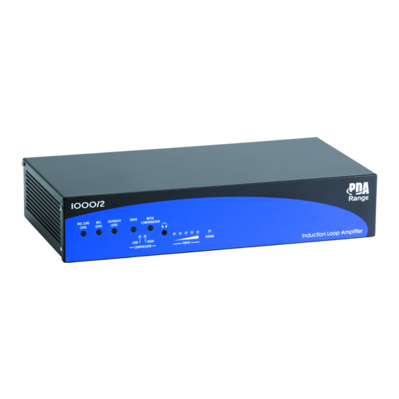
Page 4: Familiarisation With Your Pda Pro-Range Induction Loop Amplifier
(EN60127 part 2) compliant Input OFF (up) ON (down) mains fuse, as detailed below: 11V phantom on MIC. 11V phantom off PDA200/2 11V phantom on MIC./LINE 11V phantom off 2A T 20mm anti-surge MIC./LINE Line operation Mic. operation ceramic HRC type. - Page 5 Used to help combat the frequency response problems associated with appli- Variants include cations where there is excessive metal ‘absorbing’ the magnetic field. the PDA200/2 page 13 for further details. (for areas up to 200m ), the PDA500/2 (for 3.5mm LOOP OUTPUT MONITORING SOCKET...
-
Page 6: Planning The System
6 to 9 before proceeding. Area of coverage Maximum square room coverage provided by PDA Pro-Range amplifers is as follows:- PDA200/2 = 200m ; PDA500/2 = 500m ; PDA1000/2 = 900m... - Page 7 The ‘Outreach’ plate audio input extension system In addition to the amplifier’s two XLR inputs (MIC. and MIC./LINE), up to 10 additional microphone or line level inputs (any mix) can be daisychained to the amplifier’s ‘OUTREACH’ connector via a range of specially designed wall, ceiling or desk mountable single gang plates. Several different Outreach plates are available covering the most common variants of audio connector (see below) and cable lengths of up to 100m (total network length) are easily achieveable using standard two pair audio cable such as Belden 8723.
- Page 8 A typical Pro-Range multiple input induction loop system The illustration below shows a typical induction loop system for a place of worship requiring multiple audio inputs. It is designed to show all of the amplifier’s inputs being used with a microphone connected to its MIC.
- Page 9 AMR/L radio microphone (5), transmitter (6) and receiver (7) connected to the amplifier via an APQM (8) outreach plate. Existing mixer (9) for bands, etc., connected to the amplifier via an APXL outreach plate (10). Outreach network (11) Daisychain standard two pair audio cable such as Belden 8723 to all Outreach plates as appropriate.
-
Page 10: Installation
Installation Safety precautions Please refer to the safety precautions below before attempting to make any connections or operating your PDA Pro-Range induction loop amplifier. Ensure the amplifier IS NOT located in areas with high ambient temperatures or high levels of humidity, moisture or dust. It SHOULD NOT be exposed to direct sunlight or water nor be placed next to vibrating or heat-generating equipment. -
Page 11: Connecting And Testing The System
Connecting and testing the system IMPORTANT : DO NOT POWER UP THE SYSTEM UNTIL STEP 7 (OVERLEAF). THE AMPLIFIER SHOULD NOT BE OPERATED WITHOUT A LOOP CONNECTED TO IT. Install the loop - see Planning the System, pages 6 to 9, for example layouts and positioning advice. - Page 12 If this is the case, try adjusting the layout of the loop and/or consider purchasing a more powerful PDA range amplifier. If it is impossible to illuminate all of the indicators on the loop strength meter even when the DRIVE control is turned fully clockwise, the thickness (CSA) of the induction loop cable used may be insufficient for the job.
- Page 13 The following items of cost-effective PDA RANGE test equipment can be used to verify both the audio quality and the magnetic field strength of any AFILS system. ALWAYS refer to the more detailed information supplied with each unit before starting any tests.
-
Page 14: Technical Specification
Recommended loop impedance: 0.5 – 1 Ohm @ 1KHz. Will drive higher impedance loops with reduced area of coverage. Loop drive current @ 1 Ohm: PDA200/2 – 6A; PDA500/2 – 9A; PDA1000/2 – 12A. Peak loop drive current (measured over 5mS integration time): PDA200/2 - 8 Amps @ 1 Ohm, 13Amps @ 0.5 Ohm;... - Page 15 The PDA200/2 model does not require a cooling fan, as it does not generate as much heat as the larger models. In all cases the amplifiers should be operated in a cool environment, away from sources of heat and should never be covered with any object that could impede the flow of cooling air.
-
Page 16: Spares And Accessories
PDA1000/2 900m free-standing professional induction loop amplifier PDA/WM Wall mounting kit for PDA200/2, 500/2 or 1000/2 amplifier PDA/RM 19"Rack mounting kit for PDA200/2, 500/2 or 1000/2 amplifier INDUCTION LOOP CABLE - see page 6 for further information LOOP1/B 100m reel 0.5mm...
Need help?
Do you have a question about the PDA200/2 and is the answer not in the manual?
Questions and answers