Advertisement
Quick Links
Download this manual
See also:
Instruction Manual
DECLARATION OF CONFORMITY
This product is marked
2006/95/CE
– Low voltage no.
– Electromagnetic compatibility no. 89/336 ECC, 92/31 EEC
and 93/68 EEC.
This declaration will become void in case of misuse and/or non
observance though partial of manufacturer's installation and/or
operating instructions.
F-GAS Regulation (EC) No. 842/2006
Do not vent R410A into atmosphere: R410A is a fluorinated
greenhouse gas, covered by Kyoto Protocol, with a Global
Warming Potential (GWP) = 1975.
OPERATING LIMITS
L
Cooling Maximum conditions
Outdoor temperature : 43°C D.B.
Room temperature
: 32°C D.B. / 23°C W.B.
L
Cooling Minimum conditions
Outdoor temperature : 19°C D.B.
Room temperature
: 19°C D.B. / 14°C W.B.
L
Heating Maximum conditions
Outdoor temperature : 24°C D.B. / 18°C W.B.
Room temperature
: 27°C D.B.
L
Heating Minimum conditions
Outdoor temperature :
Room temperature
: 16°C D.B.
WARNING
Read the yellow instruction sheet attached to the outdoor
units.
PARTS
FIGURE
Raw plug *
Ricevitore con
cavo (5 mt.)
Remote
control
Remote control
unit holder
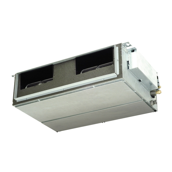
INSTALLATION INSTRUCTIONS
– Split system air conditioner –
This air conditioner uses the new refrigerant R410A.
as it satisfies Directives:
.
–15°C W.B.
ACCESSORIES SUPPLIED WITH THE UNIT
Q.TY
PARTS
AAA Alkaline
2
battery
Tapping
1
screw 4 x 30
Tapping
1
screw 3,5 x 13
1
37.4196.132.0
Model Combinations
Combine indoor and outdoor units only as listed below.
Indoor Units
SAP-URV96EH
SAP-URV126EH
SAP-URV186EH
SAP-URV246EH
FOR "MULTI SPLIT" INSTALLATION SEE "MULTI DC INVERTER
COMBINATIONS TABLE"
Power Supply:
220 - 240 V ~ 50 Hz
Tools required for installation (not supplied)
1. Standard screwdriver
2. Phillips head screwdriver
3. Knife or wire stripper
4. Tape measure
5. Level
6. Sabre saw or key hole saw
7. Hacksaw
8. Core bits ø 5
FIGURE
Q.TY
PARTS
Drain
2
elbow *
2
Drain cap *
Cushion
2
rubber *
©SANYO 2008
Outdoor Units
SAP-CRV96EH
SAP-CRV126EH
SAP-CRV186EH
SAP-CRV246EH
19. Hammer
10. Drill
11. Tube cutter
12. Tube flaring tool
13. Torque wrench
14. Adjustable wrench
15. Reamer (for reburring)
16. Hex. key
FIGURE
Q.TY
1
4
4
*
Packed in the outdoor unit.
EG
I
F
D
E
P
GR
Advertisement


Need help?
Do you have a question about the SAP-URV96EH and is the answer not in the manual?
Questions and answers