Bryant 355MAV Installation, Start-Up, And Operating Instructions Manual
I series
Hide thumbs
Also See for 355MAV:
- Installation, start-up, and operating instructions manual (60 pages) ,
- Troubleshooting manual (48 pages) ,
- Service and maintenance procedures manual (16 pages)
Table of Contents
Advertisement
NOTE: Read the entire instruction manual before starting the
installation.
This symbol → indicates a change since the last issue.
Index
SAFETY CONSIDERATIONS .....................................................2
DIMENSIONAL DRAWING........................................................3
Clearances to Combustibles......................................................4
CODES AND STANDARDS........................................................5
INTRODUCTION ..........................................................................6
APPLICATIONS............................................................................6
General ......................................................................................6
Upflow Applications.................................................................6
Downflow Applications ............................................................8
Horizontal Left (Supply-Air Discharge) Applications ..........10
LOCATION..................................................................................13
General ....................................................................................13
Low-Heat Only Installation ....................................................14
Furnace Location Relative to Cooling Equipment ................15
Hazardous Locations...............................................................15
INSTALLATION .........................................................................15
Leveling Legs (If Desired) .....................................................15
Installation In Upflow or Downflow Applications................15
Installation In Horizontal Applications ..................................17
Air Ducts.................................................................................18
General Requirements .......................................................18
Ductwork Acoustical Treatment .......................................18
Supply Air Connections ....................................................18
Return Air Connections.....................................................18
Filter Arrangement..................................................................18
Bottom Closure Panel.............................................................19
Gas Piping...............................................................................19
Electrical Connections ............................................................20
115-v Wiring......................................................................20
24-v Wiring........................................................................22
Accessories ........................................................................22
Direct Venting.........................................................................22
Common Vent Systems................................................22
Combustion-Air and Vent Piping .....................................25
Kit Installation..............................................................31
Multiventing and Vent Terminations................................34
Condensate Drain....................................................................34
installation, start-up,
and operating instructions
DELUXE 4-WAY MULTIPOISE
VARIABLE-CAPACITY DIRECT-VENT
CONDENSING GAS FURNACE
A93040
Page
-1-
Cancels: II 355M-40-13
ISO 9001:2000
REGISTERED
As an ENERGY STAR®
Partner, Bryant Heating &
Cooling Systems has de-
termined that this product
meets
the
ENERGY
STAR® guidelines for en-
ergy efficiency.
UPFLOW
HORIZONTAL
LEFT
DOWNFLOW
AIRFLOW
Fig. 1-Multipoise Orientations
General...............................................................................34
Application.........................................................................34
Condensate Drain Protection.............................................35
General...............................................................................35
Select Setup Switch Positions...........................................36
Prime Condensate Trap With Water.................................37
Purge Gas Lines ................................................................37
Sequence of Operation ......................................................37
(Adaptive Mode) ..........................................................37
Two-Stage Thermostat and Two-Stage Heating .........39
Cooling Mode...............................................................39
Thermidistat Mode .......................................................40
Super-Dehumidify Mode..............................................40
Continuous Blower Mode ............................................40
Heat Pump ....................................................................41
Component Test ...........................................................41
Adjustments .......................................................................41
Set Gas Input Rate .......................................................41
Set Temperature Rise...................................................48
Set Thermostat Heat Anticipator .................................49
355MAV
Series I
II 355M-40-14
3-05
ama
CERTIFIED
AIRFLOW
HORIZONTAL
RIGHT
AIRFLOW
AIRFLOW
A93041
®
Advertisement
Table of Contents

Related Manuals for Bryant 355MAV


Summary of Contents for Bryant 355MAV
-
Page 1: Table Of Contents
A93040 NOTE: Read the entire instruction manual before starting the REGISTERED installation. As an ENERGY STAR® Partner, Bryant Heating & This symbol → indicates a change since the last issue. Cooling Systems has de- termined that this product meets ENERGY... -
Page 2: Safety Considerations
SAFETY CONSIDERATIONS handling parts. CAUTION: FURNACE RELIABILITY HAZARD Improper installation or misapplication of furnace may The 355MAV Multipoise Condensing Gas-Fired Furnaces are require excessive servicing or cause premature compo- CSA (formerly AGA and CGA) design-certified for natural and nent failure. -
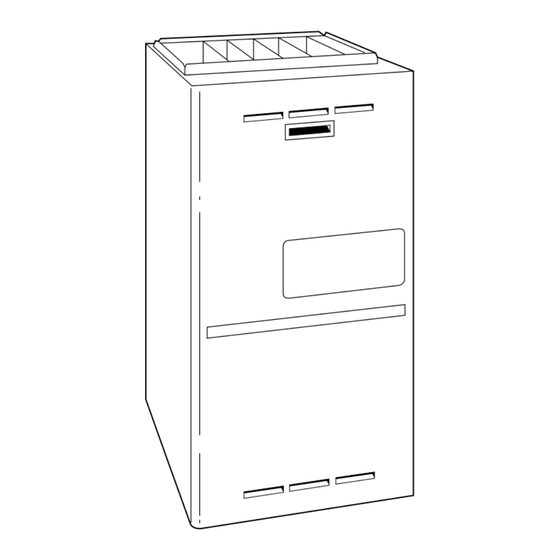
Page 3: Dimensional Drawing
—3—... -
Page 4: Clearances To Combustibles
This furnace must be installed with a direct-vent (combustion air Installer Packet includes: and flue) system and a factory accessory termination kit. In a Installation, Startup, and Operating Instructions direct-vent system, all air for combustion is taken directly from the Service and Maintenance Instructions outside atmosphere and all flue products are discharged to the User’s Information Manual... -
Page 5: Codes And Standards
18-IN. MINIMUM TO BURNERS A93044 Fig. 5—Installation in a Garage V. ACOUSTICAL LINING AND FIBROUS GLASS DUCT • US and CANADA: current edition of SMACNA, NFPA 90B as A05004 tested by UL Standard 181 for Class I Rigid Air Ducts →... -
Page 6: Introduction
A. Condensate Trap Location (Factory-Shipped INTRODUCTION Orientation) The model 355MAV 4-way multipoise, Gas-Fired, Category IV, The condensate trap is factory installed in the blower shelf and direct-vent condensing furnace is available in model sizes ranging factory connected for UPFLOW applications. A factory-supplied in input capacities of 40,000 to 120,000 Btuh. - Page 7 PLUG PLUG COLLECTOR BOX COLLECTOR BOX DRAIN TUBE (BLUE DRAIN TUBE (BLUE & WHITE STRIPED) & WHITE STRIPED) COLLECTOR BOX COLLECTOR BOX TUBE (PINK) TUBE (PINK) COLLECTOR BOX TUBE (GREEN) COLLECTOR BOX INDUCER HOUSING DRAIN TUBE (GREEN) (MOLDED) DRAIN TUBE (BEHIND COLLECTOR BOX DRAIN TUBE) CONDENSATE...
-
Page 8: Downflow Applications
3. Install casing hole filler cap (factory-supplied in loose parts UPPER INDUCER HOUSING DRAIN CONNECTION bag) into blower shelf hole where trap was removed. Attached to the UPPER (unused) inducer housing drain connection is a cap and clamp. This cap is used to prevent condensate leakage →... - Page 9 COLLECTOR BOX DRAIN TUBE (BLUE) COLLECTOR BOX PLUG TUBE (GREEN) PLUG COLLECTOR BOX TUBE (GREEN) COLLECTOR BOX DRAIN TUBE (BLUE) COLLECTOR BOX COLLECTOR BOX TUBE (PINK) TUBE (PINK) COLLECTOR BOX DRAIN TUBE (BLUE COLLECTOR BOX & WHITE STRIPED) DRAIN TUBE (BLUE &...
-
Page 10: Horizontal Left (Supply-Air Discharge) Applications
PLUG COLLECTOR BOX AUXILIARY "J" BOX DRAIN TUBE (BLUE AND WHITE STRIPED) CONDENSATE COLLECTOR BOX TRAP TUBE (GREEN) INDUCER HOUSING COLLECTOR BOX DRAIN TUBE (VIOLET) EXTENSION TUBE COLLECTOR BOX COLLECTOR DRAIN TUBE (BLUE) BOX EXTENSION DRAIN TUBE DRAIN TUBE COUPLING COLLECTOR BOX TUBE (PINK) RELOCATE TUBE BETWEEN BLOWER SHELF AND INDUCER HOUSING FOR 060, AND 080 HEATING INPUT FURNACES... - Page 11 COMBUSTION – AIR INTAKE VENT A 12-IN. MIN HORIZONTAL PIPE SECTION IS RECOMMENDED WITH SHORT (5 TO 8 FT) VENT SYSTEMS TO REDUCE EXCESSIVE CONDENSATE DROPLETS FROM ″ EXITING THE VENT PIPE. WORK AREA ″ ⁄ MANUAL SHUTOFF ACCESS OPENING GAS VALVE FOR TRAP DRAIN...
-
Page 12: Horizontal Right (Supply-Air Discharge) Applications
COLLECTOR BOX DRAIN TUBE (BLUE) COLLECTOR BOX TUBE (GREEN) PLUG COLLECTOR BOX TUBE (PINK) AUXILIARY "J" BOX RELOCATED HERE CONDENSATE TRAP COLLECTOR BOX DRAIN TUBE (BLUE AND WHITE STRIPED) INDUCER HOUSING DRAIN TUBE (VIOLET) COLLECTOR BOX EXTENSION TUBE A02289 Fig. 13—Horizontal Right Tube Configuration 3. -
Page 13: Location
NOTE: See Fig. 13 or tube routing label on main furnace door to → WARNING: CARBON MONOXIDE POISONING check for proper connections. HAZARD Relocate tubes as described below. Failure to follow this warning could result in personal injury or death. 1. -
Page 14: Low-Heat Only Installation
The furnace and its return air system shall be designed and installed so that negative pressure created by the air circulating fan This 355MAV furnace can be installed to operate in the low-heat cannot affect another appliance’s combustion air supply or act to only heating mode when sized using the low-heat heating capacity. -
Page 15: Furnace Location Relative To Cooling Equipment
INSTALLATION I. LEVELING LEGS (IF DESIRED) When furnace is used in upflow position with side inlet(s), leveling legs may be desired. (See Fig. 18.) Install field-supplied, corrosion-resistant 5/16-in. machine bolts and nuts. NOTE: The maximum length of bolt should not exceed 1-1/2 in. 1. - Page 16 PLENUM OPENING FLOOR OPENING A96283 Fig. 19—Floor and Plenum Opening Dimensions FURNACE FURNACE (OR COIL CASING WHEN USED) CD5 OR CK5 COIL ASSEMBLY OR KCAKC COIL BOX COMBUSTIBLE FLOORING COMBUSTIBLE FLOORING DOWNFLOW SHEET METAL SUBBASE PLENUM SHEET METAL FLOOR PLENUM OPENING FLOOR OPENING...
-
Page 17: Installation In Horizontal Applications
CAUTION: UNIT MAY NOT OPERATE PERFORATED Failure to follow this caution may result in intermittent DISCHARGE DUCT FLANGE unit operation or performance satisfaction. Do not bend duct flanges inward as shown in Fig. 22. This will affect airflow across heat exchangers and may cause limit cycling or premature heat exchanger failure. -
Page 18: Air Ducts
installed on non-combustible material. When installed on combus- CAUTION: UNIT MAY NOT OPERATE tible material, supply-air duct attachment must ONLY be con- Failure to follow this caution may result in intermittent nected to an accessory subbase or factory approved air condition- unit operation or performance satisfaction. -
Page 19: Bottom Closure Panel
TABLE 2—FILTER INFORMATION VII. GAS PIPING Gas piping must be installed in accordance with national and local AIR FILTER LOCATED IN BLOWER COMPARTMENT codes. Refer to NFGC in the U.S. Canadian installations must be Furnace Filter Size (In.) Filter Type Casing made in accordance with NSCNGPIC and all authorities having Framed... -
Page 20: Electrical Connections
straps, hangers, etc. Use a minimum of 1 hanger every 6 ft. Joint recommended that ground joint union be loosened before pressure compound (pipe dope) should be applied sparingly and only to testing. After all connections have been made, purge lines and male threads of joints. - Page 21 FIELD 24-V WIRING FIELD 115-, 208/230-, 460-V WIRING FACTORY 24-V WIRING FACTORY 115-, 208/230-, 460-V WIRING NOTE 5 THERMOSTAT FIVE TERMINALS FIELD-SUPPLIED WIRE DISCONNECT THREE-WIRE HEATING 208/230- OR ONLY 460-V THREE PHASE W/W1 115-V NOTE SINGLE PHASE 208/230-V SINGLE AUXILIARY PHASE 115-V J-BOX...
-
Page 22: 24-V Wiring
INSTALLED IX. DIRECT VENTING LOCATION The 355MAV furnaces require a dedicated (one 355MAV furnace only) direct-vent system. In a direct-vent system, all air for combustion is taken directly from outdoor atmosphere, and all flue gases are discharged to outdoor atmosphere. The venting system shall be installed in accordance to these instructions. - Page 23 ACRDJ PRINTED CIRCIUT BOARD TRAN PL12 1 2 3 1 2 3 1 2 3 1 2 3 1 2 3 1 2 3 1 2 3 1 2 3 7 8 7 8 7 8 7 8 OFF OFF OFF OFF PRINTED CIRCIUT BOARD —23—...
- Page 24 COMMUNICATION CONTINUOUS FAN FUTURE CONNECTOR (CF) AIRFLOW APPLICATIONS MODEL PLUG SETUP SWITCHES CONNECTOR SW1 SETUP SWITCHES AND BLOWER OFF- DELAY AIR CONDITIONING (A/C) AIRFLOW SETUP SWITCHES HUMIDIFIER TERMINAL (24-VAC 0.5 AMP MAX. ACRDJ – AIR CONDITIONING RELAY DISABLE JUMPER 24-V THERMOSTAT TERMINALS FLASH UPGRADE...
-
Page 25: Combustion-Air And Vent Piping
TABLE 5—APPROVED COMBUSTION-AIR AND VENT PIPE, FITTING AND CEMENT MATERIALS ASTM SPECIFICATION MATERIAL PIPE FITTINGS SOLVENT CEMENT AND PRIMERS DESCRIPTION (MARKED ON MATERIAL) D1527 Pipe — — Schedule-40 D1785 Pipe — — Schedule-40 Solvent D2235 For ABS — — For ABS Cement D2241 Pipe... - Page 26 25--24--65--2 AREA WHERE TERMINAL IS NOT PERMITED VENT TERMINAL AIR SUPPL Y INLET U.S. Installation (2) Item Clearance Description Canadian Installation (1) Clearance above grade, veranda, porch, deck, balcony, or 12˝ (30cm) # 12˝ (30 cm) anticipated snow level Clearance to a window or door that may be opened 12 ˝(30 cm) for appliances >...
- Page 27 NOTE: Do not count elbows or pipe sections in terminations or NOTE: Select 1 vent pipe connection and NOTE: Select 1 vent pipe connection and 1 combustion-air pipe connection. 1 combustion-air pipe connection. within furnace. See shaded areas in Fig. 37, 38, 39, 40, and 41. FLOW COMBUSTION- COMBUSTION-...
- Page 28 12 ″ MIN 12 ″ MIN VENT PIPE VENT PIPE COMBUSTION-AIR PIPE COMBUSTION-AIR PIPE HORIZONTAL TO ROOF HORIZONTAL TO SIDEWALL COMBUSTION-AIR PIPE VENT PIPE COMBUSTION-AIR PIPE 12 ″ MIN 12 ″ MIN VENT PIPE VERTICAL TO ROOF VERTICAL TO SIDEWALL NOTE: A 12 In.
- Page 29 TABLE 7—MAXIMUM ALLOWABLE PIPE LENGTH (FT) NUMBER OF 90° ELBOWS UNIT TERMINATION PIPE DIAMETER ALTITUDE SIZE TYPE (IN.)* 1-1/2 2 Pipe or 2-In. 042040 Concentric 1-1/2 2 Pipe or 2-In. 042060 Concentric 1-1/2 042080 2 Pipe or 2-In. 060080 Concentric 0 to 2000 2 Pipe or 2-In.
- Page 30 TABLE 7—MAXIMUM ALLOWABLE PIPE LENGTH (FT) Continued NUMBER OF 90° ELBOWS UNIT TERMINATION PIPE DIAMETER ALTITUDE SIZE TYPE (IN.)* 1-1/2 2 Pipe or 2-In. 042040 Concentric 1-1/2 2 Pipe or 2-In. 042060 Concentric 1-1/2 042080 2 Pipe or 2-In. 6001 to 7000‡ 060080 Concentric 2 Pipe or 2-In.
-
Page 31: Concentric Vent And Combustion-Air Termination Kit Installation
since it is less susceptible to damage, has reduced chances to take COMBUSTION – AIR INTAKE HOUSING in contaminants, and has less visible vent vapors. (See Fig. 37 or 3/8" ID TUBE BURNER 38.) Sidewall termination may require sealing or shielding of building surfaces with a corrosive resistance material due to corrosive combustion products of vent system. - Page 32 ROOF 18″ MAXIMUM BRACKET COUPLING COMBUSTION VERTICAL SEPARATION VENT BETWEEN COMBUSTION AIR AND VENT 8 3 / 4 ″ FOR 3″ KIT 6 3 / 4 ″ FOR 2″ KIT MAINTAIN 12 IN. MINIMUM CLEARANCE ABOVE HIGHEST ANTICIPATED SNOW LEVEL. MAXIMUM OF 24 IN.
- Page 33 A96128 Fig. 42—Rooftop Termination (Dimension "A" is Touching or 2-In. Maximum Separation) 1″ MAXIMUM VENT (TYP) VENT COMBUSTION AIR VENT COMBUSTION VENT A93057 A93056 Fig. 44—Concentric Vent and Combustion-Air Side Fig. 43—Concentric Vent and Combustion-Air Roof Termination (Dimension "A" is Touching or Termination (Dimension "A"...
-
Page 34: Multiventing And Vent Terminations
D. Multiventing and Vent Terminations connections (furnace, A/C, or humidifier) must be terminated into When 2 or more 355MAV Furnaces are vented near each other, an open or vented drain as close to the respective equipment as each furnace must be individually vented. NEVER common vent possible to prevent siphoning of the equipment’s drain. -
Page 35: Condensate Drain Protection
WARNING: PERSONAL INJURY AND PROPERTY DAMAGE HAZARD Failure to follow this warning could result in property damage and personal injury or death. Caution should be taken to prevent draining where slippery conditions may cause personal injuries. Exces- sive condensate draining may cause saturated soil condi- tions which could result in damage to plants. -
Page 36: Select Setup Switch Positions
5. Replace main furnace door and blower access door. CAUTION: UNIT MAY NOT OPERATE NOTE: EAC-1 terminal is energized whenever blower operates. Failure to follow this caution may result in intermittent HUM terminal is only energized when blower is energized in unit operation or performance satisfaction. -
Page 37: Prime Condensate Trap With Water
TABLE 9—FURNACE SETUP SWITCH DESCRIPTION SETUP SWITCH NORMAL DESCRIPTION SWITCH NO. NAME POSITION OF USE Turn ON to retrieve up to 7 stored status codes for troubleshooting SW1-1 Status Code Recovery assistance when R thermostat lead is disconnected. Allows 2-stage operation with a single stage thermostat. Turn ON when using 2 stage thermostat to allow Low Heat opera- SW1-2 Adaptive Heat Mode... - Page 38 NOTE: Low-heat-only switch, SW1-2, selects either the low- NOTE: The heat cycle can start in either high-or low-heat. If a heat-only operation mode when ON, (see item 2. below) or high-heat cycle is initiated, the furnace control CPU will de- adaptive heating mode when OFF, in response to a call for heat.
-
Page 39: Two-Stage Thermostat And Two-Stage Heating
115 vac power to the furnace, or by interrupting 24 vac 1. Switching From Low- To High- Heat-If the thermostat R power at SEC1 or SEC2 to the furnace control CPU (not at to W1 circuit is closed and the R to W2 circuit closes, the W/W1, G, R, etc.). -
Page 40: Thermidistat Mode
energize the Y/Y2 terminal and switch the outdoor unit to The cooling operation described in item 3. above applies to high-cooling, as long as the thermostat continues to call for operation with a Thermidistat. The exceptions are listed below: cooling. Subsequent selection is based on stored history of a. -
Page 41: Heat Pump
Verify furnace model. Table 11 can only be used for Y1 or Y/Y2, the furnace control CPU will transition to or bring on model 355MAV Furnaces. the blower motor BLWM at cooling airflow, low-heat airflow, or d. Find installation altitude in Table 11. - Page 42 A00277 A00275 Fig. 56—Two-Stage Furnace with Single-Speed Heat Pump Fig. 54—Two-Stage Furnace with Single-Speed (Dual Fuel) Air Conditioner A00276 A00278 Fig. 57—Two-Stage Furnace with Two-Speed Heat Pump Fig. 55—Two-Stage Furnace with Two-Speed (Dual Fuel) Air Conditioner —42—...
- Page 43 A00281 Fig. 60—Two-Stage Thermostat With Two-Stage A00279 Furnace and Two-Speed Air Conditioner Fig. 58—Dual Fuel Thermostat with Two-Stage Furnace and Single-Speed Heat Pump See note 2 A02348 Fig. 61—Single-Stage Thermostat With Two-Stage Furnace and Two-Speed Air Conditioner A00280 Fig. 59—Dual Fuel Thermostat With Two-Stage Furnace and Two-Speed Heat Pump —43—...
- Page 44 Notes for Fig. 54-61: 1. Heat pump MUST have a high pressure switch for dual fuel applications. 2. Refer to outdoor equipment Installation Instructions for additional information and setup procedure. 3. Select the ″ZONE″ position on the two-speed heat pump control. 4.
- Page 45 TABLE 12 - ORIFICE SIZE* AND MANIFOLD PRESSURES FOR GAS INPUT RATE (TABULATED DATA BASED ON 20,000 BTUH HIGH-HEAT / 13,000 BTUH LOW-HEAT PER BURNER, DERATED 2%/1000 FT ABOVE SEA LEVEL) ALTITUDE AVG. GAS SPECIFIC GRAVITY OF NATURAL GAS RANGE HEAT VALUE 0.58 0.60...
- Page 46 TABLE 12 - ORIFICE SIZE* AND MANIFOLD PRESSURES FOR GAS INPUT RATE (TABULATED DATA BASED ON 20,000 BTUH HIGH-HEAT / 13,000 BTUH LOW-HEAT PER BURNER, DERATED 2%/1000 FT ABOVE SEA LEVEL) ALTITUDE AVG. GAS SPECIFIC GRAVITY OF NATURAL GAS RANGE HEAT VALUE 0.58 0.60...
- Page 47 e. Turn low-heat adjusting screw (3/32 hex Allen wrench) a. Calculate high-altitude adjustment (if required). counterclockwise (out) to decrease input rate or clock- UNITED STATES wise (in) to increase input rate. At altitudes above 2000 ft, this furnace has been ap- NOTE: DO NOT set low-heat manifold pressure less than 1.3-in.
-
Page 48: Set Temperature Rise
TABLE 12—ALTITUDE DERATE MULTIPLIER FOR U.S.A. TABLE 13—GAS RATE CU FT/HR ALTITUDE % OF DERATE MULTIPLIER SECONDS SIZE OF TEST DIAL SECONDS SIZE OF TEST DIAL FOR 1 FOR 1 (FT) DERATE FACTOR REVOLUTION cu ft cu ft cu ft REVOLUTION cu ft cu ft... -
Page 49: Set Thermostat Heat Anticipator
b. Check derate for altitude if applicable. 1. The recommended method of checking this limit control is to gradually block off return air after furnace has been c. Check all return and supply ducts for excessive restric- operating for a period of at least 5 minutes. tions causing static pressure greater than 0.5-in. - Page 50 CHECKLIST—INSTALLATION LOAD CALCULATION Condensate Drain ____________ Heating Load (Btuh) ________ Unit Level or Pitched Forward ____________ Cooling Load (Btuh) Internal Tubing Connections Free of Kinks ________ and Traps ____________ Furnace Model Selection External Drain Connection Leak Tight and COMBUSTION AND VENT PIPING ________ Sloped Termination Location...
- Page 51 —51—...
- Page 52 Course descriptions and schedules are in our catalog. CALL FOR FREE CATALOG 1-800-644-5544 [ ] Packaged Service Training [ ] Classroom Service Training A94328 © 2005 Bryant Heating & Cooling Systems 7310 W. Morris St. Indianapolis, IN 46231 —52— Printed in U.S.A. 355m4014...
Need help?
Do you have a question about the 355MAV and is the answer not in the manual?
Questions and answers