Table of Contents
Advertisement
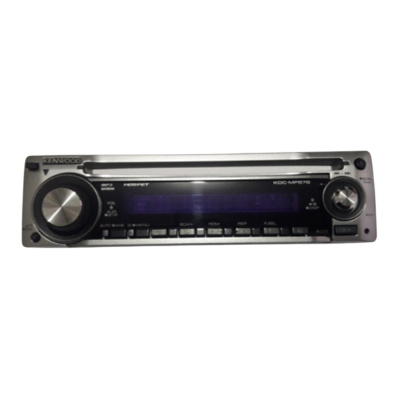
CD RECEIVER
CKDC-MP576
CKDC-MP676F
CKDC-MP676V
SERVICE MANUAL
MANUFACTURED BY VISTEON
DIM
DIM
Escutcheon
(B07-xxxx-xx)
Mounting hardware assy
(J22-0227-03)
Front glass
CKDC-MP576 (B10-4838-02)
VOL
AUD
SET UP
AUTO
AME
Q
MENU
SCAN
RDM
Front glass
CKDC-MP676F/MP676V (B10-4839-02)
VOL
AUD
SET UP
SCAN
RDM
AUTO
AME
Q
MENU
Depends on the model.
Refer to the parts list.
DC cord
(E30-6583-05)
© 2006-2 CREATED IN JAPAN
B53-0385-00 ( N ) 0
SCRL
FM
AM
REP
F.SEL
FF
SCRL
FM
AM
REP
F.SEL
FF
Carrying case
(W01-1661-05)
Lever
(D10-4705-04) x2
This product uses Lead Free solder.
Advertisement
Table of Contents

Related Manuals for Kenwood CKDC-MP576


Summary of Contents for Kenwood CKDC-MP576
-
Page 1: Service Manual
CD RECEIVER CKDC-MP576 CKDC-MP676F CKDC-MP676V SERVICE MANUAL © 2006-2 CREATED IN JAPAN B53-0385-00 ( N ) 0 MANUFACTURED BY VISTEON Front glass CKDC-MP576 (B10-4838-02) SCRL SET UP AUTO MENU SCAN F.SEL Front glass CKDC-MP676F/MP676V (B10-4839-02) SCRL SET UP SCAN F.SEL... -
Page 2: Block Diagram
CKDC-MP576 CKDC-MP676F/MP676V BLOCK DIAGRAM ELECTRIC UNIT (X34- ) R103 SERVO+B To IC1 Q901-903 PHONE PHONE Q501 Q502 DME1 OFFSET Q101 AM+B To IC1 WIRED AM AGC FM AGC CD MECHA ACC-DET REMOTE ACC DET IC14 Q103 SP-OUT To IC1 POWER... -
Page 3: Components Description
CKDC-MP576 CKDC-MP676F/MP676V COMPONENTS DESCRIPTION ELECTRIC UNIT (X34-4570-10) Ref. No. Application / Function Operation / Condition System µ-COM System control Power Supply IC DC5V x 1, 7.9V x 1, 8.1V x 2, 10.2V x 1, P-CON, P-ANT output Reset IC “L”: detection voltage below 3.6V IC10 E-VOL &... -
Page 4: Microcomputer's Terminal Description
CKDC-MP576 CKDC-MP676F/MP676V COMPONENTS DESCRIPTION CD PLAYER UNIT (X32-5860-00) Ref. No. Application / Function Operation / Condition A3.3V regulator Power supply for audio 3.3V Ope amp for low-pass filter 4ch BTL driver Driving spindle motor and loading/ejection operation Mechanism µ-com BU 3.3V regulator Power supply for backup 3.3V... - Page 5 CKDC-MP576 CKDC-MP676F/MP676V MICROCOMPUTER’S TERMINAL DESCRIPTION Truth Value Pin No. Pin Name Application Processing / Operation / Description Table CN DET Panel communication detection H: Without PANEL, L: With PANEL Not used Fix to output L KEY REQ Communication request form VFD driver...
- Page 6 CKDC-MP576 CKDC-MP676F/MP676V MICROCOMPUTER’S TERMINAL DESCRIPTION Truth Value Pin No. Pin Name Application Processing / Operation / Description Table TUNER block (in µ-com) check TUN FANC OUT Only when test mode, E2P OK: H, E2P NG: L, Normal: L PON FM...
-
Page 7: Mechanism Μ-Com: Ic4 (X32- : Cd Player Unit)
PS1-1 PS2-2 AUDIO KENWOOD brand model (initial value) OEM model (with CRSC changed) KENWOOD brand model (with CRSC changed) KENWOOD brand model (to support test-driving in EU) r : Destination change TYPE 3 TYPE 2 TYPE 1 Model (Pin 80) - Page 8 CKDC-MP576 CKDC-MP676F/MP676V MICROCOMPUTER’S TERMINAL DESCRIPTION Processing Operation Pin No. Pin Name Application Remarks Description Used with DXM-6685W (X32-586). DAC MUTE DAC MUTE control H : MUTE ON, L : MUTE OFF With DXM-6580W (X32-574), open and L-fixed. Used with DXM-6685W (X32-586).
- Page 9 CKDC-MP576 CKDC-MP676F/MP676V MICROCOMPUTER’S TERMINAL DESCRIPTION Processing Operation Pin No. Pin Name Application Remarks Description BVdd BUS interface power supply BVss BUS interface GND 57~61 AB8~AB12 Multiplex data/address 3.3V driven 62~65 Not used Low-fixed 3.3V driven Chip select control H : OFF, L : ON 3.3V driven...
-
Page 10: Test Mode
CKDC-MP576 CKDC-MP676F/MP676V TEST MODE How to enter the test mode AUDIO adjust mode Press and hold the [1] and [3] keys and reset. • Press the [AUD] key and enter the audio adjustment mode. • Press the remote controller [∗] key and [AUD] key to go into How to clear the test mode the audio adjustment mode. - Page 11 CKDC-MP576 CKDC-MP676F/MP676V TEST MODE Other [AM] IC10 adjustment status • When started in Test Mode, duration of prohibiting LINE “E2P_OK”: Adjustment completed MUTE shall be changed from 10 seconds to 1 second. “E2P_ER” : E2PROM values are still default (not determined) •...
- Page 12 • Displays power ON time is displayed (Pin 76) (Pin 77) • Displays CD operation time q KENWOOD brand model • Displays number of CD EJECT times w KENWOOD brand model High • Displays number of times panel was opened/closed (with CRSC changed) •...
- Page 13 CKDC-MP576 CKDC-MP676F/MP676V ADJUSTMENT 1. IC10 (X34-) -The Tuner adjustment method 1-3. Adjustment of FM ANT & RF coil • When IC10 and its circumference are repaired, according Voltage Check Point : S-METER-Check Land to the following order, it readjusts if needed.
- Page 14 CKDC-MP576 CKDC-MP676F/MP676V ADJUSTMENT 2. IC10 (X34-) Replacement - Parts vs Adjustment Item Table • When the parts in the following tables are exchanged, please readjust according to a table. • When other parts are exchanged, please perform only a check of operation. There is no necessity for readjustment.
- Page 15 CKDC-MP576 CKDC-MP676F/MP676V PC BOARD (COMPONENT SIDE VIEW) (FOIL SIDE VIEW) SWITCH UNIT SWITCH UNIT X16-381x-xx (J76-0166-12) X16-381x-xx (J76-0166-12) PAN SW5V ILL D GND RTRY LED+B FL+B VFD RST DATAF DATAS REMO RTRY TDF DET X16-381x-xx ESD GND Ref. No. Address...
- Page 16 CKDC-MP576 CKDC-MP676F/MP676V PC BOARD (FOIL SIDE VIEW) ELECTRIC UNIT X34-4570-10 (J76-0167-12) W603 W916 IC14 R963 R101 R102 R608 R610 R910 R908 R609 D103 W610 R903 R106 R901 W611 R107 D105 D901 W612 C605 D106 DC-DET Q101 W613 R607 R116 C801...
- Page 17 CKDC-MP576 CKDC-MP676F/MP676V C703 R963 R604 Q702 Q703 W704 R605 W705 C603 C521 X34-4570-10 C604 C529/ Ref. No. Address R979 C602 C522 C524 C701 C605 C526 C533 R522 R525 C702 L512 IC10 C534 Q502 IC11 L506 IC14 C537 L511 R978 C503...
-
Page 18: Pc Board (Component Side View)
CKDC-MP576 CKDC-MP676F/MP676V PC BOARD (COMPONENT SIDE VIEW) CD PLAYER UNIT X32-5860-00 (J76-0212-02) CP27 IC11 R150 X32-5860-00 Ref. No. Address IC11 Refer to the schematic diagram for the values of resistors and capacitors. - Page 19 CKDC-MP576 CKDC-MP676F/MP676V PC BOARD (FOIL SIDE VIEW) CD PLAYER UNIT X32-5860-00 (J76-0212-02) 12EJE-SW CP28 A3.3V REFOUTSV SHOCK LOS-SW LOCK DOUT ADIN HOLD F- F+ DOUT DGND R152 C100 R104 CP11 CP10 S7.5V BU5V SGND TYPE LOE/LIM PON2 PON1 SPD+ DMUTE BU3.3V...
- Page 20 CKDC-MP576 CKDC-MP676F/MP676V ELECTRIC UNIT (X34-4xxx-xx) R705 R701 C701 TP338 10u16 Q702 Q702 BU+5V REAR MUTE SW for Lch PRE OUT TP340 Q703 Q703 R959 MUTE SW for Rch PRE OUT R706 R702 C702 ∗ TP339 CF53 10u35 CF52 CF51 10.700 10.700...
- Page 21 CKDC-MP576 CKDC-MP676F/MP676V BU+5V BU+5V AUDIO+B CF54 Q105 450.000kHz Q503 CONTROL D110 Q104,105 TP432 MUTE R972 D112 TP502 L509 CONTROL Q104 NOISE 5.0V 5.0V 0 - 5.0V 5.0V RESET IC ∗ C582 ∗ 0.01 ∗ Q503 R210 2.6V TYPE 3 ∗...
- Page 22 SW5V BU+5V C410 SW5V AUDIO+B AUDIO+B BU+5V FL+B FL+B 1/2W 1/2W 1/2W 1/2W 1/2W CONTROL SW for FL+B FL+B AVR LED+B BU+14.4V FL+B SW BU+5V TP373 SURVO+B SURVO+B TP374 CKDC-MP576/MP676F/MP676V (1/2) SIGNAL LINE GND LINE B LINE SS'Y X34-4570-10 (3/4)
- Page 23 CKDC-MP576 CKDC-MP676F/MP676V DESTI- C523, C526, C538, MODEL UNIT No. C502 C521 C522 C524 C525 C527 C537 C556 NATION 529,531 E212/S J/J1 X34-4090-02 0.01 0.47 1000P E313S X34-4090-01 0.01 0.47 1000P X34-4090-11 1500P 100P 0.01 KDC-MP202 KDC-MP2032CR X34-4090-13 1500P 100P 0.01...
- Page 24 CKDC-MP576 CKDC-MP676F/MP676V SWITCH UNIT (X16-3xxx-xx) ANODE CONNECTION 3GA,3GB 1GA,1GB NAME R80 47 1/2W — col (Downside) R81 47 1/2W R82 47 1/2W Upside Downside col (Upside) — — — REMOTE — — ∗ SW5V SENSOR KEY MATRIX AUTO ∗ EJECT...
- Page 25 Val- TP59 TP69 ues may vary slightly due to varia- tions between individual instru- ments or/and units. EJECT TP62 TP63 TP65 TP61 ∗ ∗ ∗ ∗ ∗ GREEN ∗ LED SW LED SW 2.2K 2.2K CKDC-MP576/MP676F/MP676V (2/2) X16-381x-xx (2/2)
- Page 26 CKDC-MP576 CKDC-MP676F/MP676V (X32-586x-xx) IC1 : TAR5S33-F IC7 : UPD63763CGJ : DAP202U IC2 : NJM4580V-ZB IC9 : BR24L02FV-W UNIT DESTINATION IC3 : BA5824FP IC11 : TC7SET32FU-F 2SA1576A 0-00 IC4 : 703030BYGCJ21A : 2SB0970 VISTEON 0-02 IC5 : XC6219B332MR Q5,7 : DTA143XUA...
- Page 27 CKDC-MP576 CKDC-MP676F/MP676V LOADING & SLED SPINDLE MOTOR MOTOR (X92- ) (X92- ) NATION SIGNAL LINE GND LINE TEON B LINE 4ch BTL 2.4-4.2V 2.6-4.2V DRIVER 2.4-4.2V 2.6-4.2V TP26 TP31 S7.5V SLD+ SPD+ 1.2-5.5V 1.0-5.0V SLD+ SPD+ TP28 TP33 SLD- SPD- 1.2-5.5V...
- Page 28 CKDC-MP576 CKDC-MP676F/MP676V EXPLODED VIEW (CD MECHANISM) DPU1 DFPC1 (X32) φ : N09-4460-15 M1.7x8 : N09-6317-05 M1.7x2.5 : N09-6004-15 M2x2 : N09-6007-15 φ : N09-6051-15 2x5(BLK) : N19-2163-04 1.6 WASHER : N39-2020-48 M2x2 φ : N09-6108-15 2x3.5 φ : N09-6155-15 Parts with the exploded numbers larger than 700 are not supplied.
-
Page 29: Exploded View (Unit)
CKDC-MP576 CKDC-MP676F/MP676V EXPLODED VIEW (UNIT) DME1 : N24-3015-48 : N80-2006-48 : N80-2008-43 : N83-3005-48 : N86-2610-48 : N80-3010-48 : N83-3005-48 : N83-3020-48 : N86-2606-48 (X34) (X16-) (X34-) Parts with the exploded numbers larger than 700 are not supplied. -
Page 30: Parts List
BINDING HEAD TAPTITE SCREW DA204U DIODE 3-BT-224N FLUORESCENT INDICATOR TUBE W01-1661-05 CARRYING CASE LC75756W MOS-IC K : CKDC-MP576 K2 : CKDC-MP676F K3 : CKDC-MP676V Indicates safety critical components. (E : Europe K : North America M : Other Areas W : Without Europe) -
Page 31: Switch Unit (X16-381X-Xx)
CHIP C 47PF RK73GB2A4R7J CHIP R J 1/10W CK73GB1H103K CHIP C 0.010UF K K : CKDC-MP576 K2 : CKDC-MP676F K3 : CKDC-MP676V Indicates safety critical components. (E : Europe K : North America M : Other Areas W : Without Europe) - Page 32 35WV C503 CK73GB1H104K CHIP C 0.10UF C576 CK73GB1H103K CHIP C 0.010UF K K : CKDC-MP576 K2 : CKDC-MP676F K3 : CKDC-MP676V Indicates safety critical components. (E : Europe K : North America M : Other Areas W : Without Europe)
-
Page 33: Electric Unit (X34-4570-10)
CHIP R 2.7K J 1/10W R503 RK73EB2E222J CHIP R 2.2K J 1/4W K : CKDC-MP576 K2 : CKDC-MP676F K3 : CKDC-MP676V Indicates safety critical components. (E : Europe K : North America M : Other Areas W : Without Europe) - Page 34 1SS133 DIODE MTZJ12(B) ZENER DIODE D10-4595-04 D10-4596-24 MTZJ6.8(B) ZENER DIODE D13-2151-04 GEAR K : CKDC-MP576 K2 : CKDC-MP676F K3 : CKDC-MP676V Indicates safety critical components. (E : Europe K : North America M : Other Areas W : Without Europe)
- Page 35 DC MOTOR ASSY (SPINDLE) T42-1067-14 DC MOTOR ASSY (LOADING) DPU1 X93-2130-01 OPTICAL PICKUP ASSY (LEAD FREE) K : CKDC-MP576 K2 : CKDC-MP676F K3 : CKDC-MP676V Indicates safety critical components. (E : Europe K : North America M : Other Areas...
-
Page 36: Specifications
Weight ............3.1 lbs (1.40kg) Frequency Response (±1dB) ......10Hz~20kHz Total Harmonic Distortion (1kHz) ........ 0.01% Signal to Noise Ratio (1kHz) ........105dB KENWOOD follows a policy of continuous advancements Dynamic Range ............. 93dB in development. MP3 Decode ..Compliant with MPEG-1/2 Audio Layer-3 For this reason specifications may be changed without no- tice.
Need help?
Do you have a question about the CKDC-MP576 and is the answer not in the manual?
Questions and answers