Creda Eco-Response ER300 Installation Instructions Manual
Hide thumbs
Also See for Eco-Response ER300:
- Specification sheet (14 pages) ,
- Installation instructions manual (12 pages)
Advertisement
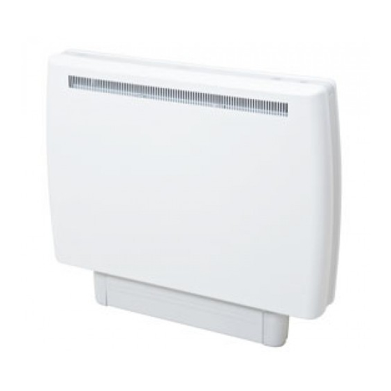
Eco-Response Radiator
Models: ER300, ER400 and ER500
Dimensions
(including clearances diagram)
(millimetres)
Models
Specification
ER300
1.3kW / 0.28kW
ER400
1.95kW / 0.34kW
ER500
2.6kW / 0.39kW
Model Height A
Width B
ER300 712mm
600mm
ER400 712mm
830mm
ER500 712mm
1050mm
THESE INSTRUCTIONS SHOULD BE READ CAREFULLY AND RETAINED FOR FUTURE REFERENCE
These instructions should not be left with the user, as this would invite the dismantling and servicing by unqualified persons.
There is a separate instruction leaflet which should be left with the user explaining how the radiator should be operated.
TO ENSURE THIS APPLIANCE IS OPERATING CORRECTLY, IT IS ESSENTIAL TO PERFORM THE CHECK PROCEDURE DETAILED ON
THE BACK PAGE OF THIS INSTRUCTION. THIS MUST BE COMPLETED BEFORE NORMAL OPERATION COMMENCES.
IMPORTANT SAFETY ADVICE
WARNING - This radiator is VERY HEAVY. In order to maintain stability and to ensure its future safety in use, it is essential
that the radiator is FIXED SOUNDLY TO A WALL and that the feet are mounted on a FIRM, LEVEL SURFACE. Care should
be taken to avoid irregular surfaces, such as may result from tiled surrounds partially protruding under the radiator. It is
important that the following instructions are strictly followed.
WARNING – It is important that the fixing device chosen is appropriate to the wall material to which the radiator is being
fixed. Some modern internal building materials are very low density block and require specialised fixing devices to
provide a safe, secure installation.
WARNING – If during any reassembly of the radiator, a part of the thermal insulation shows damage or deterioration which
may impair safety, it should be replaced with an identical part.
WARNING – This radiator must not be located below a socket outlet.
Suggested Wall Fittings (see page 7 for further information)
Solid brick/block: No. 10 Rawlplug fibre inserts (provided). 5.5mm drill bit. Drill 8mm deeper than rawlplug length.
Plasterboard: If possible locate studding and use No. 10 woodscrews directly into the wood, otherwise M5 intersets.
For other wall types seek specialist advice.
DO NOT COVER OR OBSTRUCT the surfaces of the appliance.
DO NOT POSITION under windows where curtains may contact the radiator (see minimum clearances above).
DO NOT PLACE OBJECTS in contact with the radiator.
Depth C
130mm +10mm
130mm +10mm
130mm +10mm
NOTE ALSO THE INFORMATION GIVEN ON THE APPLIANCE
Curtains
B
75mm
min.
75mm
min.
- 1 -
Installation Instructions
86576
Shelf or Overhang
250mm
min.
150mm
min.
A
Furniture
or other
obstruction
110mm
Issue 1
C
Advertisement
Table of Contents

Subscribe to Our Youtube Channel
Related Manuals for Creda Eco-Response ER300


Summary of Contents for Creda Eco-Response ER300
-
Page 1: Installation Instructions
Installation Instructions 86576 Issue 1 Eco-Response Radiator Models: ER300, ER400 and ER500 Dimensions (including clearances diagram) Shelf or Overhang Curtains (millimetres) Models Specification 250mm ER300 1.3kW / 0.28kW min. 75mm ER400 1.95kW / 0.34kW min. ER500 2.6kW / 0.39kW 75mm 150mm min. -
Page 2: Electrical Connection
Electrical Connection WARNING – THIS APPLIANCE MUST BE EARTHED The installation of this appliance should be carried out by a competent electrician in accordance with I.E.E. Regulations for Electrical Equipment. The radiator is fitted with two flexible cables for connection to the fixed wiring of the premises through suitable switched connection boxes positioned adjacent to the radiator. -
Page 3: Circuit Diagram
Circuit Diagram - 3 -... -
Page 4: Installation Of The Radiator
INSTALLATION OF THE RADIATOR ASSEMBLY Fit the feet to the radiator by engaging the flanges on the top of the foot with the slots in the base of the radiator . Push the foot towards the back of the radiator Turn the carton upside down and open the carton from until it is fully engaged the bottom. - Page 5 Stand the radiator on its feet and remove packaging Swing bottom of panel slightly away from the rest of by sliding over the top of the radiator. Remove all the radiator (Fig. 7 ) and lift upwards to unhook the additional internal protective packaging.
-
Page 6: Wall Mounting
WALL MOUNTING The following must be applied before fixing the radiator to the wall: NO SKIRTING BOARD / SKIRTING BOARD NO TALLER THAN 100MM The radiator is to be mounted as shown in Fig. 11 with the wall spacer bracket in its standard orientation. Mark the position of the two mounting slots with the radiator pushed tight against the wall Fig. - Page 7 SKIRTING BOARD TALLER THAN 100MM Use the 10mm and 30mm spacers provided (2 x 10mm and 2 x 30mm) If the skirting board is taller than 100mm, the radiator is to be mounted as shown in fig 12 . Remove the wall mounting bracket and reassemble in the IMPORTANT: UNDER NO alternative orientation to give a greater spacing...
- Page 8 Remove the inner front panel by removing the screws along its top edge Fig. 13 . Carefully lift the bottom of the front inner panel out of the retaining flange at the base of the radiator, Fig. 13 , and remove the internal packaging, Fig.
- Page 9 Refit the elements by carefully feeding the tails down through the hole in the base insulation, ensuring the tab is pointing forward. Fit the front layer of cells with the flat side toward the front of the radiator. Ensure that the tab on the element is captured below the bottom row of cells and that the element is vertical.
- Page 10 REASSEMBLY Reconnect the radiant element connector as shown in Fig 20 Hook slots at the bottom of the plinth over the plinth fixing tabs on the plastic feet, as shown in Fig. 20 . Slide the plinth into place as shown in Fig. 20c. Replace the outer front panel by hooking onto the two location clips on the top panel Fig.
- Page 11 ELECTRICAL CONNECTION IMPORTANT EPLACING MAINS WIRE ON DIRECT ACTING SUPPLY CIRCUIT . T85) ESISTING ABLE The wires in the direct acting supply cable are coloured in Follow the procedure to remove the outer front. accordance with the following code: Remove the PCB Bracket from the bottom of the outer front. Remove the wire from the connector block and earth screw.
- Page 12 CHECK PROCEDURE FOR INSTALLERS FOLLOWING INSTALLATION THIS CHECK PROCEDURE SHOULD BE CARRIED OUR BY A COMPETENT INSTALLER ONLY. A QUICK START GUIDE AND USER INSTRUCTIONS ARE AVAILABLE FOR END USERS. Eco-Response has two heat output modes Comfort (Radiant To check the radiant panel operation (comfort heat). Heat) and Background (Retained Heat) .
Need help?
Do you have a question about the Eco-Response ER300 and is the answer not in the manual?
Questions and answers