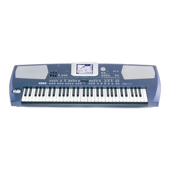
Korg PA500 Service Manual
Hide thumbs
Also See for PA500:
- User manual (292 pages) ,
- Manual (104 pages) ,
- Connecting manual (2 pages)

Related Manuals for Korg PA500


Summary of Contents for Korg PA500
- Page 1 KORG Pa500 SERVICE MANUAL TABLE OF CONTENTS ASSEMBLY SKETCH (HOOKUP): 2-3 BLOCK DIAGRAM: 4 SCHEMATIC DIAGRAM: 5-12 TEST MODE: 13-26 PARTS LIST: 27-30 Issued:Nov.15, 2007 Ver1.0...
- Page 2 Pa500 ASSEMBLE DRAW UPPER DRAW Screw information Part Cord PART NAME NOTE for metal chassis to PCB 510700503509 BT B 3BC 3 X 6 for UPPER CASE 510700503563 SCREW BT B 3BC 3X10 for KEY BORAD 510700503574 BT FEW 3BBC 3 X 16...
- Page 3 Pa500 ASSEMBLE DRAW BOTTOM SIDE DRAW Part Cord PART NAME NOTE for bottom board 510700503613 BT FEW 3BC 3 X 20 510700503614 BT B 3BBC 4X20 for UPPER side & BOTTOM side Part Cord PART NAME NOTE Standerd Pa500 510646508002...
- Page 13 How to enter the TEST MODE <<Start the TEST MODE>> Pressing the [STYLE PLAY] and the [MEDIA], turn the power on, and continue to pressing until the service menu is displayed. Confirm that big noise is not heard when power on. After the service menu is displayed, press the [PAD 2] to start the TEST MODE.
- Page 14 When you start from an item before MIDI Loop, please connect MIDI IN and MIDI OUT by a MIDI cable. <<Internal Check: NAND - MIDI Loop>> When you touch the icon of the internal check, Pa500 execute the internal check automatically. When some error is detected Pa500 displays the error item in the LCD.
- Page 15 After following display is appeared, insert the SD card. When the SD card is inserted before the SD Card Check, it is NG. After following display is appeared, insert the SD card then Pa500 begins internal check. When all items of the internal check are OK, the check proceeds to the check of the touch panel automatically.
- Page 16 When you touch the LCD, the mark appears for a while at the [ON] icon, but soon it move to the [MOVE] icon. Confirm the [MOVE] and the [OFF] icons. After confirmed them, rotate the [TEMPO/VALUE] encoder to the top-center position, then touch the [Next] icon.
- Page 17 <<Switch, Encoder, Headphones: Display>> Order Next switch to press Check Mark Encoder value Clockwise(+) Counter clockwise:(-) Switch ASSIGN SW1 [ASSIGNABLE SWITCH] All LEDs light ACCOMP. [ACCOMP.] [ACCOMP.] MEMORY [MEMORY] [MEMORY] MANUAL BASS [MANUAL BASS] [MANUAL BASS] EXIT [EXIT] All LEDs light MENU [MENU] All LEDs light...
- Page 18 Switch STYLE SELECT 2 [STYLE SELECT] [STYLE SELECT] Lower Dark Gray RECORD [RECORD] All LEDs light Dark Gray TRACK SELECT [TRACK SELECT] All LEDs light Dark Gray STS 1 All LEDs light Dark Gray STS 2 All LEDs light Dark Gray STS 3 All LEDs light Dark Gray...
- Page 19 Switch SEQ2: PAUSE [SEQ2: |<] All LEDs light SEQ2: PLAY [SEQ2: |> □] [SEQ2: |> □] STYLE CHANGE [STYLE CHANGE] [STYLE CHANGE] PERFORMANCE SELECT [PERFORMANCE] [PERFORMANCE] SOUND SELECT [SOUND] [SOUND] UPPER OCTAVE - [UPPER OCTAVE -] All LEDs light UPPER OCTAVE + [UPPER OCTAVE +] All LEDs light INTRO 1...
- Page 20 *After confirmation of the maximum and the minimum value, remove your fingers from the joystick. Damper Pedal: KORG DS-1H Maximum position (step on the pedal) less than 1.8kOhm, Minimum position (return the pedal) 16.7-35.7KOhm Assignable pedal: KORG EXP-2 Minimum resistance 100Ohm Connect the speakers to the [OUTPUT] and confirm that no sound is heard from L and R speakers and headphones.
- Page 21 Ass.Pedal: Assignable Pedal EXP-2 Reference value and each status Item Reference1 (big value) Reference2 (small value) [Slider1:] Max: more than 990 Min:less than 30 [Slider2:] Max: more than 990 Min:less than 30 [Seq Balance] Max: more than 990 Min:less than 30 [JoystickX:] left-right Right end: more than 976 Left end: less than 32...
- Page 22 <<LINE INPUT>> This is measurement output corresponding to input. Push [START/STOP] to proceed. [VOLUME] slider: Max, Equipment: LPF 20z, PSOPHO:no, MODE: AC LEVEL Oscillator: Sine-wave 1KHz, +4dBm Measurement and Reference level Measurement must be done at the same time INPUT LEVEL and Crosstalk of same number. Item Measuring Channel Reference level...
- Page 23 Connect some audio source like CD player to the [ INPUT]. Confirm that the sound is heard from the speakers. [Left-], [Right-] are displayed in the LCD, confirm that the sound is heard only from one side. In the 4,th item, above display is appeared, then push the [START/STOP]. Pa500 restarts in the normal product mode.
- Page 24 << Consumption Current >> After the restart, display becomes like following. Set the [VOLUME] slider to the maximum position. Confirm that the consumption current is 580 – 640 [mA]. <<LCD Contrast Check>> Check of the LCD contrast, watch the screen from the 50degree points. See the chart of next page.
- Page 25 “STANDARD” “limit of dark direction”...
- Page 26 The check completed. When you take out the SD card, once push then take it out. <<System Update>> Pa500 can be constantly updated as new versions of the operating system which are released by Korg. You can download the operating system from www.korgpa.com.
- Page 27 KORG Pa500 Parts List Part Number Category Part Name Location Reference 510300511005 DIGITAL TR DTC114EUA T106 (S) KIP-2150 [TOP] Q1 510310510502 DOUBLE DIODES MC2840-T112-1 (S) KIP-2150 [TOP] D2-4 510310511507 DIODE RLS-73 TE-11 (S) KIP-2150 [TOP] D5-6 [BOT] D1 D7-9 510320511003...
- Page 28 Part Number Category Part Name Location Reference 510C51532150 PCB ASS'Y KIP-2150 PA500(X-5390)ASS'Y 510300511024 TRANSISTOR 2SA1037AK T146R KLM-2820/23/25/26 [TOP] Q1-2 510300511504 TRANSISTOR 2SC3661-TB-E (S) KLM-2820/23/25/26 [TOP] Q3-8 510300511018 TRANSISTOR 2SC2412KT146R (S) KLM-2820/23/25/26 [TOP] Q9 510402511003 EMI/EMC PART BLM18BD102SN1D (S) KLM-2820/23/25/26 [TOP] L7-9 L12-14 L16-20...
- Page 29 Part Number Category Part Name Location Reference 510C51532820 PCB ASS'Y KLM-2820/23/25/26 PA500 ASS'Y 510219401920 EMI/EMC PART NFM21PC104R1E3D KLM-2828 [TOP] LC1 510310511507 DIODE RLS-73 TE-11 (S) KLM-2828 [TOP] D1-24 510320516008 Logic IC SN74LV138APWR KLM-2828 [TOP] IC1 510402511003 EMI/EMC PART BLM18BD102SN1D (S)
- Page 30 Part Number Category Part Name Location Reference 510646502120 Mechanical X-5390 BASS PORT assy L E30476-1 ASS'Y 510646502121 Mechanical X-5390 BASS PORT assy R E30476-2 ASS'Y 510646502122 Mechanical X-952 PWS KNOB (CH) E40726 ASS'Y 510646502049 Mechanical X-2100 SLIDER KNOB E40578-2 ASS'Y 510646502123 Mechanical X-610 ENCODER KNOB(CH) E40727 -1...
Need help?
Do you have a question about the PA500 and is the answer not in the manual?
Questions and answers