
Related Manuals for suprema Xpass


Summary of Contents for suprema Xpass
-
Page 1: Installation Guide
INSTALLATION GUIDE Xpass English Version 2.00 EN 101.00.XPS V2.00A... -
Page 2: Table Of Contents
Contents Safety Instructions ..................3 Getting Started ....................4 Components ..............................4 Features ................................5 Part names and features ..............................5 Cables and connectors ..............................6 Installation ......................7 Mounting the Bracket and Product ......................7 Installing the bracket ................................. 7 Connecting to Power ............................ -
Page 3: Safety Instructions
Safety Instructions Safety Instructions Please read the following instructions carefully before using the product. This information is important for ensuring the safety of the user and for preventing damage to the user's property. Warning Violation of the instructions may cause serious injury or death. Installation Instructions Do not install the product in direct sunlight or in a location that is damp or dusty. -
Page 4: Getting Started
Getting Started Getting Started Components Adapter Diode Extension bracket Main bracket Xpass TCP/IP Mounting screws for bracket PVC anchors Heat shrink Software CD extension cable (2 pcs) (2 pcs) tubes Note The components may differ depending on where the product is installed. -
Page 5: Features
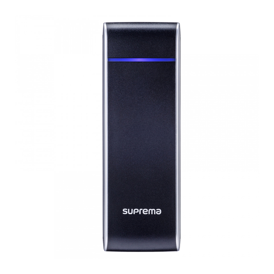
Getting Started Features Part names and features Network reset button LED lamp RF card touch area Ethernet LED Name Feature • Green: Authentication success • Red: Authentication failure • Pink: Processing • Blue and sky-blue alternate flashing every 2 seconds: Normal operation •... -
Page 6: Cables And Connectors
Getting Started Cables and connectors Pin name Color RS-485 GND White (Black stripe) Wiegand GND Black RS-485 TRX- Yellow (Black stripe) Wiegand Data 1 White RS-485 TRX + Blue (White stripe) Wiegand Data 0 Green Switch Input 1 Brown Normally Open Gray (White stripe) Switch Input GND Gray... -
Page 7: Installation
With the mounting screws for the bracket, mount the bracket firmly onto the surface where Xpass is to be installed. Note If Xpass should be installed onto a concrete wall, make a hole with a drill, and then insert a PVC anchor into the hole before screwing the mounting screw. -
Page 8: Connecting To Power
16 - Power GND Black (White stripe) (Optional) DC power Xpass Note • Use a power adapter that has a DC 12 V (± 10%) specification of with the minimum current of 1,500 mA and has IEC/EN 60950-1 certification. If the power adapter is shared by other devices, the power adapter should provide a current more than the sum of the power consumption from this device (1,500 mA) and other devices. -
Page 9: Connecting To A Network
A normal CAT-5 cable can be used to connect to a hub. Xpass LAN connection (connecting directly to a PC) Xpass can be connected directly to a PC by using a normal type CAT-5 cable because it supports an automatic MDI/MDIX function. Xpass... -
Page 10: Connecting To An Door Button/Door Sensor
7 - Switch Input 1 Brown 9 - Switch GND Gray 11 - Switch Input 0 Purple Door sensor Xpass Door button Digital input connection (Alarm, Emergency switch) 7 - Switch Input 1 Brown 9 - Switch GND Gray 11 - Switch Input 0... -
Page 11: Connecting To A Relay
Install the diode close to the door lock device. • Use a separate power source for Xpass from the door lock device. Fail Secure Lock To use fail secure lock, connect N/O terminal as shown below. Normally, there is no current flowing through the relay and the door is opened when the relay is activated by a current flows. -
Page 12: Connecting To An Automatic Door
Gray (White stripe) 10 - Common Green (White stripe) Door button Sensor Automatic door controller Door lock Xpass Connecting as a standalone - Switch GND Gray 11 - Switch Input 0 Purple - Switch Input 1 Brown 10 - Common... -
Page 13: Connecting To Secure I/O 2
White (Black stripe) 5 - RS-485 TRX+ Blue (White stripe) 3 - RS-485 TRX- Yellow (Black stripe) Input 1 Door sensor Xpass Input 0 Door button Secure I/O 2 Door lock Connecting as a Wiegand device 2 - Wiegand GND... -
Page 14: Output
18 - Power Out+ Sky-blue 20 - Power Out- Black (White stripe) Deadbolt / Door strike Xpass Note • The external output provides a maximum current of 700 mA. Resetting Network Settings Turn the power on. Press the network reset button on the rear of device until the device restart automatically. -
Page 15: Product Specifications
Product Specifications Product Specifications Product Specifications Category Feature Specification IP Rating IP 65 Main RF Card 125KHz EM, 125KHz HID Prox, 13.56MHz Mifare/DESFire Multi-Controller Yes (RF) Max. User (1:1) 40,000 Capacity Max. User (1:N) 40,000 Max. Text Log 50,000 TCP/IP RS-485 Interface Wiegand... -
Page 16: Dimensions
Product Specifications Dimensions (Unit: mm) Front view Side view Main bracket Extension bracket... -
Page 17: Fcc Compliance Information
FCC Compliance Information FCC Compliance Information THIS DEVICE COMPLIES WITH PART 15 OF THE FCC RULES. Operation is subject to the following two conditions: (1) This device may not cause harmful interference, and (2) This device must accept any interference received, including interference that may cause undesired operation. Note: This equipment has been tested and found to comply with the limits for a Class B digital device, pursuant to part 15 of the FCC Rules. -
Page 18: Appendix
Designers should keep in mind that the functions or explanations denoted as "to be implemented" or "not defined" can be changed anytime. Suprema will implement or define such items in the shortest possible time, and will not accept any liability for problems incurred including compatibility issues. - Page 19 www.supremainc.com www.supremainc.com...
Need help?
Do you have a question about the Xpass and is the answer not in the manual?
Questions and answers