Table of Contents
Advertisement
Quick Links
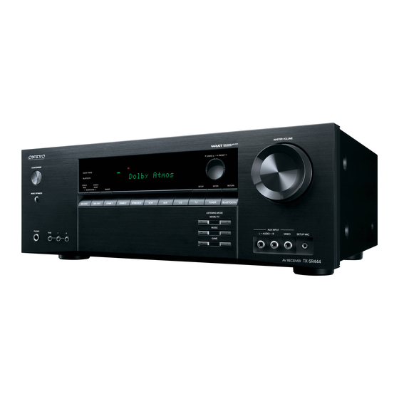
AV RECEIVER
TX-SR444
✔ Pre Issue (2015-Apr)
✔ Final Issue (2015-May)
Service Manual
CONTENTS
✔
Front Cover (This page)
✔
✔
✔
✔
✔
✔
✔
Adjustment ( Unnecessary )
✔
✔
✔
Disassembly
✔
Schematic Diagram
✔
Exploded View
✔
Appendix
SAFETY-RELATED COMPONENT WARNING!! : COMPONENTS IDENTIFIED BY MARK
THE SCHEMATIC DIAGRAM AND IN THE PARTS LIST ARE CRITICAL FOR RISK OF FIRE AND
ELECTRIC SHOCK. REPLACE THESE COMPONENTS WITH ONKYO PARTS WHOSE PART
NUMBERS APPEAR AS SHOWN IN THIS MANUAL. MAKE LEAKAGE-CURRENT OR
RESISTANCE MESUREMENTS TO DETERMINE THAT EXPOSED PARTS ARE ACCEPTABLY
INSULATED FROM THE SUPPLY CIRCUIT BEFORE RETURNING THE APPLIANCE TO THE
CUSTOMER.
Published by Onkyo & Pioneer Corporation Grobal CS Department
Ref.No. : 4518-R3
ON
Advertisement
Chapters
Table of Contents

Related Manuals for Onkyo TX-SR444


Summary of Contents for Onkyo TX-SR444
-
Page 1: Table Of Contents
SAFETY-RELATED COMPONENT WARNING!! : COMPONENTS IDENTIFIED BY MARK THE SCHEMATIC DIAGRAM AND IN THE PARTS LIST ARE CRITICAL FOR RISK OF FIRE AND ELECTRIC SHOCK. REPLACE THESE COMPONENTS WITH ONKYO PARTS WHOSE PART NUMBERS APPEAR AS SHOWN IN THIS MANUAL. MAKE LEAKAGE-CURRENT OR... -
Page 2: Note For Parts List
File Name of Parts List File (EXCEL File) Note for Parts List When parts list is EXCEL file, please refer to the following explanation about file name. PL_TX-SR343(B)MJJ.xlsx Destination Model No. Color Look at the rear panel serial number 6 digit. ○... -
Page 3: Panel
Weight : 7.8 kg (17.2 lbs.) (North American and Taiwanese), 8.0 kg (17.6 lbs.) (Others) Dimensions (W × H × D) : 435 mm × 160 mm × 328 mm, 17-1/8" × 6-5/16" × 12-15/16" TX-SR444... -
Page 4: Reset
Reset How to Reset the Unit ● How to reset: ●リセット方法 : Step1 本体のCBL/SATボタンを押しながら(必ず押した状態で2.の操作を行ってください) While holding down CBL/SAT on the main unit (note that step 2 must be performed with this button pressed down) 本体のON/STANDBYボタンを押す(表示部に「Clear」が表示されてスタンバイ状態に Step2 戻ります) Press ON/STANDBY on the main unit. ("Clear" appears on the display and the unit returns ●... -
Page 5: Amp Diag Mode After Abnormal Conditions
Protect Mode Amp Diag Mode after Abnormal Conditions The unit goes into standby automatically when detect the abnormal condition of thermal detection, dc voltage detection or current detection. (e.g. TX-SR343 block diagram below) BAPRC-1758 BAETC-1713 THERMAL THERMAL DETECT Q6300 SPRLF Q7009 VOLH M POWER... - Page 6 Self-diagnostics Amp Diag Mode after Abnormal Conditions This function is for avoiding the rupture of electrolytic capacitors with amplifier circuit failure during power-ON. Operation of Self-diagnostic Display of during Self-diagnostics Self-diagnostic will start at the timing of next power on, after goes to the protect mode 2 Line FL tube type by Current detection or DC voltage detection.
- Page 7 Repair Process and How to Confirm Amp Diag Mode after Abnormal Conditions Confirmation of the protect cause Protected by current detection While NG channel is displayed, You can confirm the protect cause by following the step below. 1. Press the Enter button 2.
-
Page 8: Model And Destination
[TV] + [ON/STANDBY] → [DIMMER] or [RT/PTY/TP] → [TONE +] x 4 Model Name Destination FL Display TX-SR343 S R 3 TX-SR343 S R 3 TX-SR343 S R 3 TX-SR343 S R 3 TX-SR444 S R 4 TX-SR444 S R 4 TX-SR444 S R 4 HT-R494 HT-R494 TX-SR343/444/HT-R494... -
Page 9: Firmware
Step2 : [TONE +] Download the firmware file (package file) from the Onkyo FTP-server. However European DSP Firmware Version will appear on the main unit’s display. service partners should download the firmware file (package file) from the ExtraNet. - Page 10 How to Update (service mode) 1/2 Firmware Overwriting is also possible. MMC -> ALL: ALL firmware update (default) MMC -> DSP: DSP firmware update Connect the MMC card JIG(0J34) with MMC card that is already all firmware in it to JIG MMC ->...
- Page 11 How to Update (service mode) 2/2 Firmware Wait until update is completed. When the update ends, “Completed!” is displayed. When “ Completed!” message appeared, you can power off by pressing “ ON/STANDBY” button. (If you leave it, it automatically turns standby mode. ) Press [ON/STANDBY] button, and the unit turns on.
-
Page 12: Hookup And Setting
Hookup and Setting No Sound ■ No sound from connected player □ Chose input selector which is assigned to connected input terminal ? □ Isn’t muting on ? ■ No sound from connected TV □ Chose wrong input selector ? □... - Page 13 Hookup and Setting No Picture ■ In general □ Connection cable is bent , twisted or damaged ? □ Input is switched on TV ? ■ No picture from connected player by HDMI input terminal □ Chose input selector which is connected to player ? □...
- Page 14 Hookup and Setting No Power ■ In general □ Doesn't be connection cable bent, be it twisted and be it damaged? ■ There is time when indication on the front panel doesn't just light up. □ Please check the connecting cord of a DISPLAY PCB. ■...
-
Page 15: Trouble Shoot
No Sound (HDMI in) Trouble Shoot Here the trouble shoot which focuses on the hardware troubles regarding PCB assembly is explained. Of course, with actual repair there are also troubles due to damaged Power Transformer, Wiring, soldering etc. in addition to PCB assembly. Process Check Point Damaged PCB... - Page 16 No Sound (Opt in) Trouble Shoot Here the trouble shoot which focuses on the hardware troubles regarding PCB assembly is explained. Of course, with actual repair there are also troubles due to damaged Power Transformer, Wiring, soldering etc. in addition to PCB assembly. Process Check Point Damaged PCB...
- Page 17 No Sound (Analog in) Trouble Shoot Here the trouble shoot which focuses on the hardware troubles regarding PCB assembly is explained. Of course, with actual repair there are also troubles due to damaged Power Transformer, Wiring, soldering etc. in addition to PCB assembly. Process Check Point Damaged PCB...
-
Page 18: Bavd
No Picture (HDMI in/ out) Trouble Shoot Here the trouble shoot which focuses on the hardware troubles regarding PCB assembly is explained. Of course, with actual repair there are also troubles due to damaged Power Transformer, Wiring, soldering etc. in addition to PCB assembly. Process Check Point Damaged PCB... -
Page 19: Baprc
No Picture (Component in/ HDMI out) Trouble Shoot Here the trouble shoot which focuses on the hardware troubles regarding PCB assembly is explained. Of course, with actual repair there are also troubles due to damaged Power Transformer, Wiring, soldering etc. in addition to PCB assembly. Process Check Point Damaged PCB... - Page 20 No Picture (Component in/ HDMI out) Trouble Shoot Here the trouble shoot which focuses on the hardware troubles regarding PCB assembly is explained. Of course, with actual repair there are also troubles due to damaged Power Transformer, Wiring, soldering etc. in addition to PCB assembly. Process Check Point Damaged PCB...
-
Page 21: Baaf
No Power Trouble Shoot Here the trouble shoot which focuses on the hardware troubles regarding PCB assembly is explained. Of course, with actual repair there are also troubles due to damaged Power Transformer, Wiring, soldering etc. in addition to PCB assembly. Process Check Point Damaged PCB... -
Page 22: Baprc
Check Point (BAPRC-1758) Trouble Shoot P2801B Check voltage ● No.2 pin : +15V P2800B Check voltage ● No.7 pin : +3.3V P2800B Check signal ● No.1 pin : 3.3V Input terminal : HDMI IN or OPT IN Input signal : Test disc 1kHz 0dB Audio format : LPCM, Dolby Digital(Otherwise, CD) P8002A Check voltage... -
Page 23: Baaf
Input signal(HDMI/OPT IN) : Test disc 1kHz 0dB Audio format : LPCM, Dolby Digital(Otherwise, CD) Q6060 Q6050 Input signal(ANALOG IN) : 1kHz 2Vrms Master volume : 46 TX-SR444/ HT-R494 only ●Each voltage is shown as the reference value. Back Value error : Plus or minus 15% TX-SR343/444/HT-R494... - Page 24 Check Point (BAPRC-1758) Trouble Shoot P2801B Check voltage ● No.2 pin : +15V P2800B Check voltage ● No.11 pin : +5V P2800B Check signal ● No.13 pin : signal ca. 1.4V 64μS ● No.15 pin : signal ca. 1.4V 64μS ●...
- Page 25 Normal (OK) or blown (No good) F6402 RL9001 Front T9002 Check damage ● Normal (OK) or blown (No good) A401 R9015 R9016 J9032 J9031 A404 R9017 C9022 C9030 C9033 P9022 P9011A A405 BAAF-1712 F6401 F6402 Front Back TX-SR444/ HT-R494 only TX-SR343/444/HT-R494...
-
Page 26: Bacla
R5181 C5041 Q6040 Q6030 R5190 R5180 J5021 J5020 J5022 R6072 C5002 C5012 R6071 R6070 C5000 C5010 C5001 C5011 J5012 J5011 J5010 C6042 C6041 C6040 R5032 R5031 R5030 CAM54 J5001 J5000 P6002A P6001A P6000A BAAF-1712 Front TX-SR444/ HT-R494 only Back TX-SR343/444/HT-R494... - Page 27 Check Point (BAPRC-1758) Trouble Shoot P7001 ● Check damage and connection How to check 1.Disconnect the FFC from the socket. 2.Check the contacts of the FFC. P9011B Check voltage ● No.4 pin : +14V P9011B Check voltage ● No.5 pin : +8.7V P9011B Check signal ●...
- Page 28 Check Point (BAPS-1737) Trouble Shoot RL9001 Check operation of a relay by sound. No sound at all ---> No good P9002 Check voltage H - L : AC100 - 240V (Power supply voltage) P9002 P9001A A402 P9021 A403 P9002 F9001 C9001 Front RL9001...
- Page 29 Check Point (BADIS-1732) Trouble Shoot P7001 ● Check damage and connection How to check 1.Disconnect the FFC from the socket. 2.Check the contacts of the FFC. A110 A107 C7515 J7009 C7513 S7622 C7514 A118 J7010 J7054 J7011 J7016 J7050 A121 D7561 A127 C7508...
-
Page 30: Bavd
Summary Disassembly This model can be disassembled in the order shown below. TOP COVER FRONT PANEL Tuner & Power Supply PROCESSOR PCB Refer to 「Front Panel Section」 Refer to 「Tuner & Power Supply Section」 Refer to 「Processor Section」 BADIS-1732 BARF-1738 BAPRC-1758 BAETC-1715 BAPS-1737... -
Page 31: Front Panel Section
Front Panel Section Disassembly This is TX-SR343. TX-SR444 / HT-R494 are same mostly structurally. Please refer to PANEL pages for detailed place by the terminal. BADIS-1732 BAETC-1715 BARF-1764 TX-SR343/444/HT-R494... - Page 32 Tuner & Power Supply Section Disassembly This is TX-SR343. TX-SR444 / HT-R494 are same mostly structurally. Please refer to PANEL pages for detailed place by the terminal. BARF-1738 BAPS-1737 TX-SR343/444/HT-R494...
-
Page 33: Baprc
Processor Section Disassembly This is TX-SR343. TX-SR444 / HT-R494 are same mostly structurally. Please refer to PANEL pages for detailed place by the terminal. BAPRC-1758 TX-SR343/444/HT-R494... -
Page 34: Video Section
Video Section Disassembly This is TX-SR343. TX-SR444 / HT-R494 are same mostly structurally. Please refer to PANEL pages for detailed place by the terminal. BAVD-1735 TX-SR343/444/HT-R494... -
Page 35: Amplifier Section
Amplifier Section Disassembly This is TX-SR343. TX-SR444 / HT-R494 are same mostly structurally. Please refer to PANEL pages for detailed place by the terminal. BACLA-1734 BAAF-1712 TX-SR343/444/HT-R494... -
Page 36: Bavd
Schematic Diagram Block Diagrams (Audio section) MODEL NO. TX-SR343/444,HT-R494 BLOCK DIAGRAM (PART-1) AUDIO SECTION BADIS1732 BAAF1712 AUX IN BAETC1715 (FRONT IN) TX-SR444,HT-R494 HP DET MIC AMP HEADPHONES FRONT BOARD Q4001 MIC DET POWER AMPLIFIER NJW1298 +29dB FRONT LEFT TUNER PACK... -
Page 37: Baprc
Schematic Diagram Block Diagrams (Video section) Model No.TX-SR343/444,HT-R494 SCHEMATIC DIAGRAM (PART-2) BLOCK DIAGRAM(VIDEO) BAPRC1758 HDMI MEMORY SPI for UPDATE Q8000 HDMI TMDS TMDS REPEATER MN864788A RPWR HP DET TMDS TMDS TMDS TMDS RPWR RPWR HP DET HP DET AUDIO IN TMDS I2S from DSP TMDS... - Page 38 Schematic Diagram Block Diagrams (Digital Audio section) MODEL NO.TX-SR343/444,HT-R494 SCHEMATIC DIAGRAM (PART3) BLOCK DIAGRAM (Digital Audio) MAIN OUT CS49844 BT MODULE HDMI IN1 HDMI IN2 CH1ABCLK 36 HDMI Tranceiver MANI 8ch HDMI IN3 MN864788A CH1ALRCLK Q1004 CH1ASD0 34 Q8000 ADSP_MCLK SCKI ADSP1_BCK ADSP1_LRCK...
-
Page 39: Baaf
Schematic Diagram ASP section MODEL NO. TX-SR343/444/HT-R494 SCHEMATIC DIAGRAM (PART-4) TO MAIN AMP (PART5) FROM BADIS-1658(PART-8) HDMI 1.0mm Pitch JamperLead FROM BAPRC-1758(PART-9) P101B P8002B P7003B 1.0mm Pitch FFC P8001B NSCT-23P2414 NSCT-7P2100 NSCT-17P2408 1 2 3 4 5 6 7 1 2 3 4 5 6 7 8 9 10 11 12 13 14 15 16 17 18 19 20 21 22 23 1 2 3 4 5 6 7 8 9 10 11 12 13 14 15 16 17 BAAF-1712(1/2) SPRLZB... - Page 40 Schematic Diagram AMP section MODEL NO. TX-SR343/444/HT-R494 SCHEMATIC DIAGRAM (PART-4) AMP SECTION P6401B P6402B CRIMP AS CRIMP AS BAAF-1712(2/2) (RED) (BLU) EU/EX Table:W ASP/AMP L6000-06 *P6605B R6693 R6430-36 NSCT-5P876 GNDDG P6005B J6700-06 R5183 NSCT-5P896 R6023 1/4W Q6033 +B1C TTC004B_Q(S AV=29dB +57V IPRO 1/4W...
-
Page 41: Baprc
Schematic Diagram AMP section (Thermal sensor) MODEL NO. TX-SR343/444,HT-R494 SCHEMATIC DIAGRAM AMP SECTION (PART-4) BAETC-1713 SENSOR Q6300 LM61CIZ Q6300A C6302 (PTH) 104Z 1.5mm JUMPER LEAD 1 2 3 P501A HDMI TO BAPRC-1758(PART-9) -
Page 42: Bacla
Schematic Diagram AMP section (Voltage amp.) MODEL NO. TX-SR343/444,HT-R494 SCHEMATIC DIAGRAM(PART-5) AMP SECTION BACLA-1734 CLASS A R5181 1/4W R6021 1/4W Q5031 INA6006AP1-T111 IN_FL GNDIN_FL C5011 +B1L 47u 50V R5001 R5021 R5031 -B1L 1/4W +BL2 -BL2 TRIML R5041 1.8k Q5051 2SC2412K-R Q5041 INC6006AP1-T111 R5191... - Page 43 P9021 NEJITANSI ST3 NEJITANSI ST3 DA2J10100 Q9011 KRC105S Type AC POWER IN Resistor D9025 DA2J10100 TX-SR343 US,EU,EX,JP R9015 100ohm 82ohm C9002 TX-SR444 US,EU,EX R9016 104Z HT-R494 US,EU,EX R9017 Jumper 82ohm P9001A NPLG-2P631 F9001D F9001C P9002 RL9001 NSCT-1P2031 NSCT-1P2031 NPLG-2P631 AC_POWER...
-
Page 44: Bavd
Schematic Diagram Video section MODEL No. TX-SR343/444 , HT-R494 SCHEMATIC DIAGRAM(Part-7) VIDEO SECTION Q2201:4053 BAVD-1735 ON SWITCH Component2-BD/DVD(PB,PR_IN) P2206 Component1-GAME2(PB,PR_IN) PRIN_1 NONE PRIN_2 C2216 C2102 103K 4053 R2102 2.2u PbIN_0 R2207 10k Q2002 TP10 Vcc 16 R2208 10k Y_COM 15 TP11 TP12 Y_COM... - Page 45 Schematic Diagram Display section MODEL NO.TX-SR343/ TX-SR444 / HT-R494 SCHEMATIC DIAGRAM (PART-8) DISPLAY SECTION Q7502 BADIS-1732 16-BT-168GNK FLAC2 DISPLAY C7511 C7512 Ek(+8.2V) 223K 223K C7510 223K R7508 R7507 FLDCLK FLDSDO FLDCS KEYINT0 L7532 FLDRST LBC2518T2R2M KEYINT1 REMIN +3.3S KEY3 VOLA...
- Page 46 Schematic Diagram Phone jack section MODEL NO.TX-SR343/444 , HT-R494 SCHEMATIC DIAGRAM (PART-8) HEADPHONE SECTIO BAETC-1715 HEADPHONE R6692 GND_DG P7201 1/2W HPDET J7201 L7201 NC LBC2518T2R2M GND_HP 1/2W 390 L7202 NC R6691 LBC2518T2R2M MSJ-064-05A SR L7203 NC LBC2518T2R2M P7202 NEJITANSI ST3...
-
Page 47: Baprc
Schematic Diagram MPU section MODEL NO.TX-SR343/444,HT-R494 SCHEMATIC DIAGRAM (PART9 : 1/5 P.12) MPU SECTION BAPRC-1758 (1/5) 13:M3;14:B10;14:P8;15:R5 HDMI_PON DIG_SDI 15:R4;16:B7 DIG_SDI (DSP_MIDO) DIG_SDO Destination of MICDET 15:R4;16:B7 DIG_SDO (DSP_MODI) DIG_CLK 15:R4;16:B7 DIG_CLK EEPROM R7125 R7126 FLMD0 10kohm DAC_CS 15:R5 DAC_CS Q7001 RESET 220kohm... - Page 48 Schematic Diagram VPU/ Power supply section MODEL NO.TX-SR343/444,HT-R494 SCHEMATIC DIAGRAM (PART-9 : 2/5 P.13) VMPU/POWER SUPPLY SECTION BAPRC-1758 (2/5) +3.3V_VMPU ETM_DATA0 ETM_DATA1 LOADER_RDY 12:C8 LOADER_RDY ETM_DATA2 VM_RST 12:C8 VM_RST ETM_DATA3 VM_RDY VM_RDY 12:C8 GNDDG VM_CLK 12:C8 VM_CLK +3.3V_VMPU VM_MOVI 12:C8 VM_MOVI SWD_DATA VM_MIVO...
- Page 49 Schematic Diagram Video processor section MODEL NO.TX-SR343/444,HT-R494 SCHEMATIC DIAGRAM (PART-9 : 3/5 P.14) VIDEO PROCESSOR SECTION L8160 +1.1VHD BAPRC-1758 (3/5) +3.3VATX_788 BLM15PX121SN1D +3.3VHD L8161 +3.3VARX0_788 BLM15PX121SN1D +1.1V L8162 C8152 +5.2VHD +3.3VARX1_788 BLM15PX121SN1D 226M MM3503A11 6.3V L8151 L8163 Q8034 SPIFLASH_UPG +1.1VATX_788 BLM15PX121SN1D C8153 +3.3VARX2_788...
-
Page 50: Baaf
Schematic Diagram DIR/ DAC/ BT section MODEL NO.TX-SR343/444,HT-R494 SCHEMATIC DIAGRAM (PART-9 : 4/5 P15) DIR/DAC/BT SECTION BAPRC-1758 (4/5) VOL_CLK VOL_CLK 12:M3 VOL_DAT VOL_DAT 12:M3 VOL_LAT VOL_LAT 12:M3 VPROTECT VPROTECT 12:M3 IPROTECT IPROTECT 12:M3 SEC1H SEC1H 12:M3 VOLH TO BLUETOOTH MODULE TO AMPLIFIRE SECTION VOLH 12:M3... -
Page 51: Dsp Section
Schematic Diagram DSP section MODEL NO.TX-SR343/444,HT-R494 SCHEMATIC DIAGRAM (PART-9 : 5/5 P.16) DSP SECTION BAPRC-1758 (5/5) Q3401 343:Winbond W25Q32FVSSIG (32MBit) 222W0135R2 DIR PART 444:SPANSION S25FL164K0XMFI013 (64Mbit) DIR_BCK_DSDCLK DSP_DBDA DIR_BCK_DSDCLK 22242955R2 DIR_LRCK2 DSP_DBCK DIR_LRCK2 DIRSD0_DSD_00 DIRSD0_DSD_00 HDMI_CSW_DSD_01 HDMI_CSW_DSD_01 HDMI_SLR_DSD_02 HDMI_SLR_DSD_02 HDMI_SBLR_DSD_03 HDMI_SBLR_DSD_03 ADSP2_BCK_DSD_04 ADSP2_BCK_DSD_04... -
Page 52: Tuner Section
Schematic Diagram Tuner section MODEL NO. TX-SR343/444,HT-R494 SCHEMATIC DIAGRAM (PART-10) TUNER SECTION MODEL NO. TX-NR545/646/747,DTR-20.7/30.7/40.7 SCHEMATIC DIAGRAM (PART-11) TUNER SECTION BARF-1738:TX-SR343/444,HT-R494 BARF-1731:TX-NR545/646/747 BARF-1730:DTR-20.7/30.7/40.7 TEST PARTS VDDRF VDD2 +3.3V 332K GND1 VDD2 100D VDDRF 473K 330n 090D 101J FRF1 RFGND VDD1 +3.3V GNDRF IISD... - Page 53 Schematic Diagram Bluetooth module connector section MODEL NO. TX-SR343/444,HT-R494 SCHEMATIC DIAGRAM (PART-14) Bluetooth module Connector Section BARF-1764 SIDE TP101 C794 9PIN BLUETOOTH MODULE 104K TP102 TP103 Q781 +3.3VBT HRM1034 TP104 BT_RST TP105 BT_LRCLK TP106 R795 BT_DAT GND4 TP107 BT_BCLK TP41 GND1 SPK_RP TP108...
- Page 54 Overview Exploded View A401 <NOTE> No description screw is 3TTB +8B(BC). 3TTB+8B(BC) Silver model only Unit : mm 3TTB+8B(3CM)SR A403 3TTB+8B(3CM)SR Refer to “heat sink section” x 9 pcs. Refer to “rear section” 4TTC+8C(3BC)SR T901 x 4 pcs. Refer to “front section” A002 x 4 pcs.
-
Page 55: Front Section
Cependant, cet équipement doit être installé et utilisé en gardant une distance de 20 cm ou plus entre le dispositif rayonnant et le corps (à l’exception des extrémités : mains, poignets, pieds et chevilles). This is TX-SR343. TX-SR444 / HT-R494 are same mostly structurally. Please refer to PANEL pages for detailed place by the terminal. -
Page 56: Heat Sink Section
Heat sink section Exploded View BAETC-1736 BAETC-1714 3SMS8W.SW+14B(CU) BAETC-1713 x 10pcs. Q6062 Q6050 Q6060 Q6054 Q6064 Q6052 Q6053 Q6063 Q6051 Q6061 TX-SR343/444/HT-R444... -
Page 57: Rear Section
P2800 P8002 F9001 BACLA-1734 U002B BAVD-1735 FUSE F6402 U002A BARF-1738 FUSE F6401 P101 3P+6FN(3BC) x 5 pcs. BAAF-1712 This is TX-SR343. TX-SR444 / HT-R494 are same mostly structurally. Please refer to PANEL pages for detailed place by the terminal. TX-SR343/444/HT-R444... - Page 58 Packing Section Exploded View TX-SR343...
- Page 59 Operation Check Appendix Initial Setting for Shipping (Service Information is also cleared.) About Button Action Use the following expression simplify description button operation. Step1 Set the volume level as 25. Example-1 : [TV/CD] + [/ standby] → [BD/DVD] Step2 [TONE] + [ON/STANDBY] → [Return] x 2 Means press the [/ standby] at [TV/CD] button is pressed, then both button to speak, [BD/DVD] Display "All Clear"...
- Page 60 Operation Check Appendix How to enter to a test mode How to check FL Display Step1 : Set the volume level as 25. Step1 : Set VOL Level = 25 Step2 : [TV] + [ON/STANDBY] Step2 : [TV] + [ON/STANDBY] → [DIMMER] or [RT/PTY/TP] Display “TEST-_”...
-
Page 61: Debug Mode
Debug Mode Appendix Audio debug mode The operations of DSP and DIR etc. are able to checked by the information displayed on FL in this FL Display debug mode. This information will help to analysing digital audio no sound trouble. :... - Page 62 Debug Mode Appendix FL Display FL Display : : : : : : 1. st_srd.lmd 6. Audio input channel 9. Display inhibit frag 2. st_srd.extdec C_LM_LAST ANA Analog display inhibit SET C_EXTDEC_OFF C_LM_PURE COX Coaxial display inhibit CLR C_EXTDEC_20_PLII C_LM_DIRECT OPT Optical C_EXTDEC_20_PLIIX C_LM_STEREO...
- Page 63 Debug Mode Appendix FL Display FL Display : . : : 11. source_format 14. Information of the input 15. Information of the LFE channel input 12. st_srd.fs UNLK DDR_UNLOCK SW 0ch ??? unknown channels for listening mode DDR_ANALOG SW 1ch transition 008 8kHz C_FMT_UNKNOWN...
- Page 64 Debug Mode Appendix FL Display FL Display : : : : : : 18. Audio output OK/NG 20. Details of the format for the FL 21. Dialog norm 22. Return value of DIRINIT request dir decode OK Dialog norm value from 0 to 31 display (DDC_STATUS) LOCK...
- Page 65 Debug Mode Appendix FL Display FL Display 26. Audio IF DA830 input 35. Information of the input MCLK of 30. DIR sequence number 33. Information of the input FS of AUD_IF_I2S_H SEQ_DIG_POWEROFF DA830 DA830 C_FS_UNKNOWN AUD_MCLK_64Fs AUD_IF_DSD SEQ_DIG_RESET C_FS_08 AUD_MCLK_128Fs AUD_IF_I2S SEQ_DIG_POWERON_WAIT AUD_IF_NET...
- Page 66 Debug Mode Appendix HDMI resolution display HDMI-related operations can be checked to some extent by displaying HDMI resolution display mode. How to enter to this mode Step1 : [ENTER] Hold down for 3 seconds The display order Display of the input signal Step1 : Display of the input signal (for 5 seconds) Step2 : Display of the output signal (for 5 seconds) TX-SR343/444/HT-R494...
- Page 67 Debug Mode Appendix Display of the input signal Digital Input signal Display 1 0 8 0 p / 6 0 1 6 : 9 → ・DVI 4 8 0 Resolution Frame rate Aspect ratio scaling 4 8 0 P Analog d e o 4 8 0 4 : 3 ・VGA(DVI)
- Page 68 Debug Mode Appendix Display of the output signal Output resolution Output signal Display Y C b C r 4 2 0 3 6 b ・RSEN OFF R G B 4 8 b color space depth ・EDID_READ_NG D V I 2 4 b Output resolution (4k scaling) 4 K 6 0 p 4 2 0 3 0 b...
- Page 69 Service Information Mode Appendix Listening Mode Code List Service Information Mode C_LM_LAST Displaying Service information C_LM_PURE This service information display system is helpful in analyze the status when the unit goes into C_LM_DIRECT C_LM_STEREO Protect mode and is powered off. Pay attention that the status will change if a button is pushed. C_LM_MONO C_LM_SURR How to enter to service information mode.
-
Page 70: Exploded View Parts List
1/39 PAGE TX-SR444(B)MDC <Note> Parts marked by "NSP" are generally unavailable because <Notes> they are not in our Master Spare Parts List. (B) : Black color model <MDC> : 120V NOTE : THE COMPONENTS IDENTIFIED BY THE MARK Canadian/USA/(Mexico) model ! ARE CRITICAL FOR RISK OF FIRE AND ELECTRIC SHOCK. - Page 71 2/39 PAGE Q6066 or TRANSISTOR 2SA1695-O ( 1) 2202513 Q6066 or TRANSISTOR 2SA1695-P ( 1) 2202516 Q6066 or TRANSISTOR 2SA1941-R ( 1) 2203052 [CHASSIS SCREW] A002 BOTTOM LEG phi48(313) 27175472 A003 CUSHION (ZUL) phi20 x phi8 28141900 A101 REAR PANEL TXSR444MDC 27124639A [CABINET]...
- Page 72 3/39 PAGE TX-SR444(B)MDC PACKING PROCEDURES PARTS LIST REF. NO. PART NAME DESCRIPTION Q'TY PART NO. (SN) REMARKS [PACKING] A601 (AS)444 29092709A A601A (L)444 { 1} 29092710 A601B (R)444 { 1} 29092711A A602 (650 x 600 x 0.515) 29100267 A603 TAPE (SEROHAN)NITTO NO.29...
- Page 73 4/39 PAGE TX-SR444(B)MDC PC BOARD PARTS LIST U001 BAAF-1712-1A : NSP CIRCUIT NO. P ART NAME DESCRIPTION Q'TY PART NO. (SN) REMARKS [SEMI CONDUCTOR] D4173 ZENER DIODE DZ2J068M0L 224760680R2 D4173 or ZENER DIODE UDZS6.8B ( 1) 224550680R2 D4174 ZENER DIODE...
- Page 74 5/39 PAGE D6024 CHIP TYPE DIODE DA2J10100 223303R2 D6024 or CHIP TYPE DIODE 1SS352 ( 1) 223234R2 D6025 CHIP TYPE DIODE DA2J10100 223303R2 D6025 or CHIP TYPE DIODE 1SS352 ( 1) 223234R2 D6026 CHIP TYPE DIODE DA2J10100 223303R2 D6026 or CHIP TYPE DIODE 1SS352 ( 1)
- Page 75 6/39 PAGE Q5054 TRANSISTOR 2SC2412K-R 2214653R2 Q5055 TRANSISTOR 2SC2412K-R 2214653R2 Q5056 TRANSISTOR 2SC2412K-R 2214653R2 Q6000 TRANSISTOR 2SD2704K 2218130R2 Q6001 TRANSISTOR 2SD2704K 2218130R2 Q6002 TRANSISTOR 2SD2704K 2218130R2 Q6003 TRANSISTOR 2SD2704K 2218130R2 Q6004 TRANSISTOR 2SD2704K 2218130R2 Q6005 TRANSISTOR 2SD2704K 2218130R2 Q6006 TRANSISTOR 2SD2704K 2218130R2 Q6013...
- Page 76 7/39 PAGE C1723 CHIP TYPE CERAMIC CAPACITOR CC725CH1H-102J1 342101024R1 C1724 CHIP TYPE CERAMIC CAPACITOR CC725CH1H-102J1 342101024R1 C1725 CHIP TYPE CERAMIC CAPACITOR CC725CH1H-102J1 342101024R1 C1726 CHIP TYPE CERAMIC CAPACITOR CC725CH1H-102J1 342101024R1 C1727 CHIP TYPE CERAMIC CAPACITOR CC725CH1H-102J1 342101024R1 C4003 CHIP TYPE CERAMIC CAPACITOR CC725CH1H-221J1 342102214R1 C4004...
- Page 77 8/39 PAGE C4169 CHIP TYPE CERAMIC CAPACITOR CK725B1H-104K1 332101045R1 C4170 TF TYPE PLASTIC FILM CAPACITOR ECQ-V50V-104J 374721044T C4170 or FILM C C281H104J20A21A ( 1) 376821044T C4171 TF TYPE PLASTIC FILM CAPACITOR ECQ-V50V-104J 374721044T C4171 or FILM C C281H104J20A21A ( 1) 376821044T C4172 UTSP TYPE ELECTROLYTIC CAPACITOR...
- Page 78 9/39 PAGE C6053 TF TYPE PLASTIC FILM CAPACITOR ECQ-V50V-224J 374722244T C6054 TF TYPE PLASTIC FILM CAPACITOR ECQ-V50V-224J 374722244T C6055 TF TYPE PLASTIC FILM CAPACITOR ECQ-V50V-224J 374722244T C6056 TF TYPE PLASTIC FILM CAPACITOR ECQ-V50V-224J 374722244T C6250 TF TYPE PLASTIC FILM CAPACITOR ECQ-V50V-473J 374724734T C6251...
- Page 79 10/39 PAGE R1725 CHIP TYPE CARBON RESISTOR RN72K1J-471JE 435034714R1 R1726 CHIP TYPE CARBON RESISTOR RN72K1J-471JE 435034714R1 R1727 CHIP TYPE CARBON RESISTOR RN72K1J-471JE 435034714R1 R1730 CHIP TYPE CARBON RESISTOR RN72K1J-471JE 435034714R1 R1731 CHIP TYPE CARBON RESISTOR RN72K1J-471JE 435034714R1 R1732 CHIP TYPE CARBON RESISTOR RN72K1J-471JE 435034714R1 R1733...
- Page 80 11/39 PAGE R4059 CHIP TYPE CARBON RESISTOR RN72K1J-104JE 435031044R1 R4060 CHIP TYPE CARBON RESISTOR RN72K1J-104JE 435031044R1 R4078 CHIP TYPE CARBON RESISTOR RN72K1J-473JE 435034734R1 R4079 CHIP TYPE CARBON RESISTOR RN72K1J-473JE 435034734R1 R4082 CHIP TYPE CARBON RESISTOR RN72K1J-104JE 435031044R1 R4087 CHIP TYPE CARBON RESISTOR RN72K1J-222JE 435032224R1 R4088...
- Page 81 12/39 PAGE R4403 CHIP TYPE CARBON RESISTOR RN72K1J-224JE 435032244R1 R5003 CHIP TYPE CARBON RESISTOR RN72K1J-000JE 435030004R1 R5004 CHIP TYPE CARBON RESISTOR RN72K1J-000JE 435030004R1 R5005 CHIP TYPE CARBON RESISTOR RN72K1J-000JE 435030004R1 R5006 CHIP TYPE CARBON RESISTOR RN72K1J-000JE 435030004R1 R5013 CHIP TYPE CARBON RESISTOR RN72K1J-563JE 435035634R1 R5014...
- Page 82 13/39 PAGE R5185 NON-FLAMMABLE CARBON FILM RESISTOR R25J-10 415471004T R5186 NON-FLAMMABLE CARBON FILM RESISTOR R25J-10 415471004T R5193 NON-FLAMMABLE CARBON FILM RESISTOR R25J-10 415471004T R5194 NON-FLAMMABLE CARBON FILM RESISTOR R25J-10 415471004T R5195 NON-FLAMMABLE CARBON FILM RESISTOR R25J-10 415471004T R5196 NON-FLAMMABLE CARBON FILM RESISTOR R25J-10 415471004T R5303...
- Page 83 14/39 PAGE R6111 METAL OXIDE FILM RESISTOR RS2WBJ-0.22 442722294T R6112 METAL OXIDE FILM RESISTOR RS2WBJ-0.22 442722294T R6113 METAL OXIDE FILM RESISTOR RS2WBJ-0.22 442722294T R6114 METAL OXIDE FILM RESISTOR RS2WBJ-0.22 442722294T R6115 METAL OXIDE FILM RESISTOR RS2WBJ-0.22 442722294T R6116 METAL OXIDE FILM RESISTOR RS2WBJ-0.22 442722294T R6120...
- Page 84 15/39 PAGE R6225 CHIP TYPE CARBON RESISTOR RN72K1J-220FE 435032202R1 R6226 CHIP TYPE CARBON RESISTOR RN72K1J-220FE 435032202R1 R6230 CHIP TYPE CARBON RESISTOR RN72K1J-000JE 435030004R1 R6231 CHIP TYPE CARBON RESISTOR RN72K1J-000JE 435030004R1 R6232 CHIP TYPE CARBON RESISTOR RN72K1J-000JE 435030004R1 R6233 CHIP TYPE CARBON RESISTOR RN72K1J-000JE 435030004R1 R6234...
- Page 85 16/39 PAGE P501 WIRE HARNESS ASSEMBLY NSAS-3P2094 2009991283UL P501A WIRE HOL NSCT-3P874 25051087 P501Aor WIRE HOL CHD-1.5-3 ( 1) 25053535 P5506B RETAINER (TRM) 25060507 P5509A RETAINER (TRM) 25060507 P6000B PLUG NPLG-9P0964 25056014 P6001B PLUG NPLG-9P0964 25056014 P6002B PLUG NPLG-9P0964 25056014 P6003A WIRE HOL NSCT-9P900...
- Page 86 17/39 PAGE D2103 CHIP TYPE DIODE DA2J10100 223303R2 D2103 or CHIP TYPE DIODE 1SS352 ( 1) 223234R2 D2104 CHIP TYPE DIODE DA2J10100 223303R2 D2104 or CHIP TYPE DIODE 1SS352 ( 1) 223234R2 D2301 DIODE G10XB80-02-60A-T16 22380378F D2302 CHIP TYPE DIODE DA2J10100 223303R2 D2302 or...
- Page 87 18/39 PAGE Q2003 HYBRID IC 74VHC4051AFT 22274051ER2TO Q2021 PHOTO COUPLER JSR1165-001recieving 24120143 Q2022 PHOTO COUPLER JSR1165-001recieving 24120143 Q2051 HYBRID IC TC74HCU04AF 222740046R2TO Q5000 TRANSISTOR 2SC2713-BL 2213136R2 Q5001 TRANSISTOR 2SC2713-BL 2213136R2 Q5002 TRANSISTOR 2SC2713-BL 2213136R2 Q5010 TRANSISTOR 2SC2713-BL 2213136R2 Q5011 TRANSISTOR 2SC2713-BL 2213136R2 Q5012...
- Page 88 19/39 PAGE T9002 POWER TRANSFORMER NPT-1520JQ 2301812A CRYSTAL HC-49S 9B12.000MHz 3010533 [CAPACITOR] CHIP TYPE CERAMIC CAPACITOR CC725CH1H-101J1 342101014R1 CHIP TYPE CERAMIC CAPACITOR CC725CH1H-090D1 342100902R1 CHIP TYPE CERAMIC CAPACITOR CK725B1C-104K1 332121045R1 CHIP TYPE CERAMIC CAPACITOR CC725CH1H-220J1 342102204R1 C2001 CHIP TYPE CERAMIC CAPACITOR CK725F1E-104Z1 332161040R1 C2012...
- Page 89 20/39 PAGE C5081 CERAMIC CAPACITOR CC45SL50V-040C 345020401T C5082 CERAMIC CAPACITOR CC45SL50V-040C 345020401T C5090 UPZ TYPE PLASTIC FILM CAPACITOR 2AUPZTF101JE 376331014T C5091 UPZ TYPE PLASTIC FILM CAPACITOR 2AUPZTF101JE 376331014T C5092 UPZ TYPE PLASTIC FILM CAPACITOR 2AUPZTF101JE 376331014T C5100 VR TYPE ELECTROLYTIC CAPACITOR CE04W100V-22M(VR) 394692207T C5101...
- Page 90 21/39 PAGE C9001 or IS TYPE CAPACITOR ECQU2A103MLC ( 1) 3800039S C9002 CHIP TYPE CERAMIC CAPACITOR CK725F1E-104Z1 332161040R1 C9011 CHIP TYPE CERAMIC CAPACITOR CC725CH1H-102J1 342101024R1 C9022 JAMICON TYPE ELECTROLYTIC CAPACITOR CE04W25V-2200M 398552227S C9022 or VR TYPE ELECTROLYTIC CAPACITOR CE04W25V-2200M(VR) ( 1) 394652227S C9030 JAMICON TYPE ELECTROLYTIC CAPACITOR...
- Page 91 22/39 PAGE R5041 CHIP TYPE CARBON RESISTOR RN72K1J-182JE 435031824R1 R5042 CHIP TYPE CARBON RESISTOR RN72K1J-182JE 435031824R1 R5050 CHIP TYPE CARBON RESISTOR RN72K1J-562JE 435035624R1 R5051 CHIP TYPE CARBON RESISTOR RN72K1J-562JE 435035624R1 R5052 CHIP TYPE CARBON RESISTOR RN72K1J-562JE 435035624R1 R5060 CHIP TYPE CARBON RESISTOR RN72K1J-182JE 435031824R1 R5061...
- Page 92 23/39 PAGE R7303 CHIP TYPE CARBON RESISTOR RN72K1J-000JE 435030004R1 R7502 CHIP TYPE CARBON RESISTOR RN72K1J-332JE 435033324R1 R7503 CHIP TYPE CARBON RESISTOR RN72K1J-332JE 435033324R1 R7504 CHIP TYPE CARBON RESISTOR RN72K1J-221JE 435032214R1 R7505 CHIP TYPE CARBON RESISTOR RN72K1J-221JE 435032214R1 R7507 CHIP TYPE CARBON RESISTOR RN72K1J-221JE 435032214R1 R7508...
- Page 93 24/39 PAGE R7812 CHIP TYPE CARBON RESISTOR RN72K1J-391JE 435033914R1 R7814 CHIP TYPE CARBON RESISTOR RN72K1J-224JE 435032244R1 R7815 CHIP TYPE CARBON RESISTOR RN72K1J-391JE 435033914R1 R7816 CHIP TYPE CARBON RESISTOR RN72K1J-391JE 435033914R1 R7820 CHIP TYPE CARBON RESISTOR RN72K1J-473JE 435034734R1 R7834 CHIP TYPE CARBON RESISTOR RN72K1J-102JE 435031024R1 R7950...
- Page 94 25/39 PAGE S7612 PUSH SWITCH NPS-111-S681 25035718T S7613 PUSH SWITCH NPS-111-S681 25035718T S7614 PUSH SWITCH NPS-111-S681 25035718T S7615 PUSH SWITCH NPS-111-S681 25035718T S7616 PUSH SWITCH NPS-111-S681 25035718T S7618 PUSH SWITCH NPS-111-S681 25035718T S7619 PUSH SWITCH NPS-111-S681 25035718T S7620 PUSH SWITCH NPS-111-S681 25035718T S7621...
- Page 95 26/39 PAGE D8962 DIODE RB050M-30GTR 22380373R2 D8963 DIODE RB050M-30GTR 22380373R2 D8964 CHIP TYPE DIODE 1SR154-400 22380284R2 D8965 CHIP TYPE DIODE DA2J10100 223303R2 D8965 or CHIP TYPE DIODE 1SS352 ( 1) 223234R2 Q1004 HYBRID IC PCM1690DCAR 22242599R2 Q1005 HYBRID IC PCM9211PTR 22242703R2 Q1007 HYBRID IC...
- Page 96 27/39 PAGE Q8709 or TRANSISTOR RN1102 ( 1) 2218230R2 Q8714 TRANSISTOR KRC402E 2218330R2 Q8714 or TRANSISTOR RN1102 ( 1) 2218230R2 Q8715 TRANSISTOR KRC402E 2218330R2 Q8715 or TRANSISTOR RN1102 ( 1) 2218230R2 Q8716 TRANSISTOR KRC402E 2218330R2 Q8716 or TRANSISTOR RN1102 ( 1) 2218230R2 Q8717 TRANSISTOR...
- Page 97 28/39 PAGE L8202 CORE BLM15PX181SN1D 2350033R1 L8205 CORE BLM15PX181SN1D 2350033R1 L8207 CORE BLM15PX181SN1D 2350033R1 L8210 CORE BLM15PX181SN1D 2350033R1 L8701 CORE BLM15PX181SN1D 2350033R1 L8702 CORE BLM15PX181SN1D 2350033R1 L8931 CHOKE COIL BLM21PG221SN1 230949R2 L8932 CHOKE COIL 1255AS-100M 231482M100R2 L8933 CHOKE COIL BLM21PG221SN1 230949R2 L8934 CHOKE COIL...
- Page 98 29/39 PAGE C3113 CHIP TYPE CERAMIC CAPACITOR CK725B1C-104K0 332011045R1 C3114 CHIP TYPE CERAMIC CAPACITOR CK725B1C-104K0 332011045R1 C3115 CHIP TYPE CERAMIC CAPACITOR CK725B1H-103K0 332031035R1 C3117 CHIP TYPE CERAMIC CAPACITOR CK725B1A-105K0 332001055R1 C3166 CHIP TYPE CERAMIC CAPACITOR CK725B1A-105K0 332001055R1 C3202 CHIP TYPE CERAMIC CAPACITOR CK725B1A-105K0 332001055R1 C3401...
- Page 99 30/39 PAGE C7027 CHIP TYPE CERAMIC CAPACITOR CK725B1H-102K0 332031025R1 C7028 CHIP TYPE CERAMIC CAPACITOR CK725B1H-102K0 332031025R1 C7029 CHIP TYPE CERAMIC CAPACITOR CK725B1H-102K0 332031025R1 C7030 CHIP TYPE CERAMIC CAPACITOR CK725B1A-105K0 332001055R1 C7031 CHIP TYPE CERAMIC CAPACITOR CK725B50V-224K 332242245R1 C7032 CHIP ELECT C CEWT6.3V-470M 395724717R2 C7033...
- Page 100 31/39 PAGE C8093 CHIP TYPE CERAMIC CAPACITOR CK725B1C-104K0 332011045R1 C8094 CHIP TYPE CERAMIC CAPACITOR CC725CH1H-101J0 342031014R1 C8095 CHIP TYPE CERAMIC CAPACITOR CC725CH1H-120J0 342031204R1 C8096 CHIP TYPE CERAMIC CAPACITOR CC725CH1H-150J0 342031504R1 C8102 CHIP TYPE CERAMIC CAPACITOR CK725B1C-104K0 332011045R1 C8153 CHIP TYPE CERAMIC CAPACITOR CK725B0J-226M 332092267R2 C8154...
- Page 101 32/39 PAGE C8932 CHIP TYPE CERAMIC CAPACITOR CK725B1C-104K0 332011045R1 C8933 CHIP TYPE CERAMIC CAPACITOR CK725B1E-106K 332221065R2 C8934 CHIP TYPE CERAMIC CAPACITOR CK725B1E-106K 332221065R2 C8935 CHIP TYPE CERAMIC CAPACITOR CK725B1H-103K0 332031035R1 C8936 CHIP TYPE CERAMIC CAPACITOR CK725B0J-226M 332092267R2 C8937 CHIP TYPE CERAMIC CAPACITOR CK725B0J-226M 332092267R2 C8941...
- Page 102 33/39 PAGE R1076 CHIP TYPE CARBON RESISTOR RN72K1J-000JE 435030004R1 R1077 CHIP TYPE CARBON RESISTOR RN72K1J-000JE 435030004R1 R1081 CHIP TYPE CARBON RESISTOR RN72K1J-221JE 435032214R1 R1085 CHIP TYPE CARBON RESISTOR RN72K1J-221JE 435032214R1 R1115 CHIP TYPE CARBON RESISTOR RN72K1J-221JE 435032214R1 R3112 CHIP TYPE CARBON RESISTOR RN72K1J-101JE 435031014R1 R3113...
- Page 103 34/39 PAGE R3466 CHIP TYPE CARBON RESISTOR RN72K1J-102JE 435031024R1 R3469 CHIP TYPE CARBON RESISTOR RN72K1J-222JE 435032224R1 R3470 CHIP TYPE CARBON RESISTOR RN72K1J-222JE 435032224R1 R3473 CHIP TYPE CARBON RESISTOR RN72K1J-103JE 435031034R1 R3474 CHIP TYPE CARBON RESISTOR RN72K1J-103JE 435031034R1 R3481 CHIP TYPE CARBON RESISTOR RN72K1J-332JE 435033324R1 R3484...
- Page 104 35/39 PAGE R7044 or CHIP RESISTOR NETWORK MNR04MRAPJ470 ( 1) 43464747004R2 R7045 CHIP TYPE CARBON RESISTOR RN72K1J-221JE 435032214R1 R7046 CHIP TYPE CARBON RESISTOR RN72K1J-221JE 435032214R1 R7047 CHIP TYPE CARBON RESISTOR RN72K1J-221JE 435032214R1 R7048 CHIP TYPE CARBON RESISTOR RN72K1J-221JE 435032214R1 R7049 CHIP TYPE CARBON RESISTOR RN72K1J-221JE 435032214R1...
- Page 105 36/39 PAGE R7182 CHIP TYPE CARBON RESISTOR RN72K1J-272JE 435032724R1 R7183 CHIP TYPE CARBON RESISTOR RN72K1J-272JE 435032724R1 R7184 CHIP TYPE CARBON RESISTOR RN72K1J-103JE 435031034R1 R7187 CHIP TYPE CARBON RESISTOR RN72K1J-104JE 435031044R1 R7188 CHIP TYPE CARBON RESISTOR RN72K1J-104JE 435031044R1 R8001 CHIP TYPE CARBON RESISTOR RN72K1J-182JE 435031824R1 R8002...
- Page 106 37/39 PAGE R8108 CHIP TYPE CARBON RESISTOR RN72K1J-103JE 435031034R1 R8109 CHIP TYPE CARBON RESISTOR RN72K1J-000JE 435030004R1 R8110 CHIP TYPE CARBON RESISTOR RN72K1J-472JE 435034724R1 R8111 CHIP TYPE CARBON RESISTOR RN72K1J-221JE 435032214R1 R8112 CHIP TYPE CARBON RESISTOR RN72K1J-105JE 435031054R1 R8113 CHIP TYPE CARBON RESISTOR RN72K1J-000JE 435030004R1 R8114...
- Page 107 38/39 PAGE R8633 CHIP TYPE CARBON RESISTOR RN72K1J-473JE 435034734R1 R8634 CHIP TYPE CARBON RESISTOR RN72K1J-473JE 435034734R1 R8635 CHIP TYPE CARBON RESISTOR RN72K1J-102JE 435031024R1 R8636 CHIP TYPE CARBON RESISTOR RN72K1J-103JE 435031034R1 R8643 CHIP TYPE CARBON RESISTOR RN72K1J-473JE 435034734R1 R8644 CHIP TYPE CARBON RESISTOR RN72K1J-473JE 435034734R1 R8645...
- Page 108 39/39 PAGE P3100 SOCKET UJA01SB4090-72R 25053533R2 P501B PLUG NPLG-3P916 25055963R2 P7001A SOCKET IMSA-9618S-23A 25053348R2 P7051A SOCKET NSCT-9P2472 25052575R2 P7053 SOCKET IMSA-9618S-09A 25053334R2 P7801 SOCKET NSCT-9P2472 25052575R2 P780A PLUG NPLG-9P1106 25056167R2 P8001 SOCKET 51U019S-3HFDN-BD-SM 25053549R3 P8001 or SOCKET HDMI(47266-4101) ( 1) 25053389R3 P8001 or SOCKET...
Need help?
Do you have a question about the TX-SR444 and is the answer not in the manual?
Questions and answers