
Related Manuals for Carrier KSACN0101AAA


Summary of Contents for Carrier KSACN0101AAA
-
Page 1: Installation Instructions
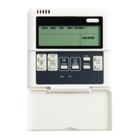
KSACN0101AAA Wired Remote Controller (with Timer Function) For Ductless Systems Installation Instructions NOTE: Read the entire instruction manual before starting the installation. -
Page 2: Table Of Contents
TABLE OF CONTENTS PAGE SAFETY CONSIDERATIONS ........COMPATIBILITY TABLE . - Page 3 WARNING INSTALLATION Entrust the distributor or authorized professionals to install the unit. Installation by unskilled persons may lead to improper installation, electric shock, or fire. Re−installation must be performed by authorized professionals. Non−compliance may lead to electric shock or fire. CAUTION EQUIPMENT DAMAGE HAZARD Failure to follow this warning may result in equipment...
- Page 4 WARNING ELECTRICAL SHOCK HAZARD Failure to follow this warning could result in personal injury or death. Before beginning any modification or installation of this kit, be sure the main electrical disconnect is in the OFF position. Ensure power is disconnected to the fan coil unit. On some systems both the fan coil and the outdoor unit may be on the same disconnect.
-
Page 5: Compatibility Table
COMPATIBILITY TABLE Table 1 – Compatibility INDOOR UNIT 40MAQB09B--1 619PAQ009BBMA 40MAQB12B--1 619PAQ012BBMA 40MAQB09B--3 619PEQ009BBMA 40MAQB12B--3 619PEQ012BBMA HIGH WALL 40MAQB18B--3 619PEQ018BBMA 40MAQB24B--3 619PEQ024BBMA 40MAQB30B--3 619PEQ030BBMA 40MAQB36B--3 619PEQ036BBMA 40MBQB09C--3 619REQ009CBMA CASSETTE 40MBQB12C--3 619REQ012CBMA 40MBQB18C--3 619REQ018CBMA 40MBQB09D--3 619REQ009DBMA 40MBQB12D--3 619REQ012DBMA 40MBQB18D--3 619REQ018DBMA DUCTED 40MBQB24D--3 619REQ024DBMA 40MBQB36D--3... - Page 6 COMPATIBILITY TABLE (CONT) INDOOR UNIT 40MKCB18C--3 40MKCB34C--3 40MKCB34C--3 40MKCB34C--3 40MKCB34C--3 CASSETTE 40MKCB34C--3 40MKQB34C--3 40MKQB34C--3 40MKQB34C--3 40MKQB34C--3 40MKQB34C--3 40MKCB18F--3 40MKCB34F--3 40MKCB34F--3 40MKCB34F--3 40MKCB34F--3 40MKCB34F--3 40MKCB54F--3 40MKCB54F--3 40MKCB54F--3 UNDERCEILING 40MKCB54F--3 - FLOOR CONSOLE 40MKCB54F--3 40MKCB54F--3 40MKQB36F--3 40MKQB36F--3 40MKQB36F--3 40MKQB36F--3 40MKQB48F--3 40MKQB48F--3 40MKQB48F--3...
-
Page 7: Installation
INSTALLATION Installation precautions for the wired remote controller: Do not install in a location near heavy oil, vapor or sulfurated gas otherwise this product will deform which will lead to a system malfunction. Do not install the unit in a location near flammable gas leaks. Once flammable gases leak and are left near the wired controller, a fire may occur. -
Page 8: Part List
PARTS LIST Kit Contents: Confirm that all the following parts are included. Table 2 – Supplied Parts DESCRIPTION Qty. REMARKS Wired Remote Controller Installation and owner's manual Screws M4X20 (for mounting on the wall) Wall plugs For wall mounting Screws M4X25 (for mounting on the wall) Plastic screw bars For fixing on the switch box... -
Page 9: Dimensions
DIMENSIONS 4.7in (120mm) .83in (21mm) .52in (13.1mm) 1.9inches (50mm) CONNECTION DIAGRAM... -
Page 10: Installation
INSTALLATION 1. Connect the female joint of the wires group from the main board to the male joint of the connective wires group. 2. Connect the other side of the connective wires group with the male joint of the wires group leads from the wired controller. - Page 11 5. Fasten the back plate of the wired controller. 6. For exposed mounting, fasten the back plate on the wall with the 3 screws (M4x20) and plugs. 7. For flush−mounting, fasten the back plate of the switch box with 2 screws (M4x25) and then fasten it to the wall with 1 screw (M4x20).
- Page 12 NOTE: Place on a flat surface. Be careful not to distort the back plate of the wired controller by over tightening the mounting screws. 8. For exposed mounting there are four outlet positions and three require cutting.
- Page 13 0.75 in (20mm)
- Page 14 NOTE: To keep water from entering the wired remote controller, use a trap and putty to seal the wired connectors during the wiring installation. During installation, reserve a certain length of the connecting wire to make removing the wired remote controller easier during maintenance. 9.
Need help?
Do you have a question about the KSACN0101AAA and is the answer not in the manual?
Questions and answers