Sony VPL-FH36 Operating Instructions Manual
Hide thumbs
Also See for VPL-FH36:
- Quick reference manual (148 pages) ,
- Manual (116 pages) ,
- Operating instruction (7 pages)
Table of Contents
Advertisement
Data
Projector
Operating Instructions
Before operating the unit, please read this manual and supplied Quick Reference Manual
thoroughly and retain it for future reference.
VPL-FH36/FH35/FH31/FH30
VPL-FX37/FX35/FX30
Not all models are available in all countries and area. Please check
with your local Sony Authorized Dealer.
© 2010 Sony Corporation
4-426-908-14 (2)
Advertisement
Table of Contents

Related Manuals for Sony VPL-FH36


Summary of Contents for Sony VPL-FH36
-
Page 1: Operating Instructions
Before operating the unit, please read this manual and supplied Quick Reference Manual thoroughly and retain it for future reference. VPL-FH36/FH35/FH31/FH30 VPL-FX37/FX35/FX30 Not all models are available in all countries and area. Please check with your local Sony Authorized Dealer. © 2010 Sony Corporation... -
Page 2: Table Of Contents
Table of Contents Overview Network Location and Function of Controls ..3 Using Network Features ....33 Main Unit ........3 Displaying the Control Window of the Projector with a Web Terminals ........4 Browser ........33 Remote Commander and Control Confirming the Information Panel .......... -
Page 3: Location And Function Of Controls
B Overview Location and Function of Controls Main Unit qa qd9q;4 1 4 5 3 qs qg qh a Lens (page 44) l Terminals (page 4) b Focus ring (page 13) m Remote control receiver The remote control receivers are located c Zoom lever (page 13) at the front and rear of the projector. -
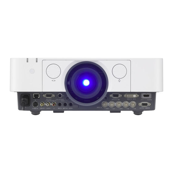
Page 4: Terminals
INPUT B) or a video signal input from the input terminal (INPUT A). Video: DVI-D input terminal (DVI-D) Audio: Audio input terminal (AUDIO) Others d INPUT D (VPL-FH36/FH35/FH31/ h RS-232C terminal FH30 only) RS-232C compatible control terminal Video: HDMI input terminal (HDMI) -
Page 5: Remote Commander And Control Panel
Remote Commander b Selecting an input signal (page 12) INPUT key (main unit) Direct input select keys (Remote STANDBY Commander) VPL-FH36/FH35/FH31/FH30: The E INPUT and F keys are not used with this projector. VPL-FX37/FX35/FX30: The D, E, and VIDEO VIDEO F keys are not used with this projector. - Page 6 *1: Use this key when inputting a One picture display computer signal. But it may not be enabled, depending on the resolution of the input signal and when displaying a two pictures (VPL-FH36/ FH35/FH31/FH30 only). *2: Use this key when inputting a computer signal. TWIN key f Setting the energy–saving mode...
- Page 7 2 Press the V/v key or ECO MODE key You do not need to install batteries in the to select ECO or User mode. Remote Commander, as the power is ECO: Sets each mode to the optimum supplied from the projector. energy-saving value.
-
Page 8: Connecting The Projector
Computer Audio cable (Stereo mini plug) (not supplied) Note It is recommended that you set the resolution of your computer to 1920 × 1200 pixels (VPL-FH36/ FH35/FH31/FH30) or 1024 × 768 pixels (VPL-FX37/FX35/FX30) for the external monitor. Connecting the Projector... -
Page 9: Connecting A Video Equipment
DVI-D cable terminal (not supplied) Audio output terminal Audio cable Computer (Stereo mini plug) (not supplied) INPUT D (VPL-FH36/FH35/FH31/FH30 only) For connecting a computer with a HDMI output terminal. HDMI output terminal HDMI cable INPUT D HDMI (not supplied) Computer Notes •... - Page 10 Audio output terminal Video equipment Audio cable (Phono plug × 2 – stereo mini plug) (not supplied) INPUT D (VPL-FH36/FH35/FH31/FH30 only) For connecting video equipment with a HDMI output terminal. HDMI output terminal HDMI cable INPUT D HDMI (not supplied)
-
Page 11: Connecting An External Monitor And Audio Equipment
To attach the HDMI cable Fix the cable to the cable tie holder at the bottom of the projector, using a commercially available cable tie, as in the illustration. Use a cable tie of less than 1.9 mm × 3.8 mm in thickness. Cable tie holder Bottom of the projector Cable tie... -
Page 12: Projecting/Adjusting An Image
B Projecting/Adjusting an Image Projecting an Image The size of a projected image depends on the distance between the projector and screen. Install the projector so that the projected image fits the screen size. For details on projection distances “Projection Distance and Lens Shift Range” (page 59) and projected image sizes, see Input select window Input... -
Page 13: Adjusting The Focus, Size, And Position Of The Projected Image
Adjusting the Focus, Size, and Position of the Projected image Focus Size (Zoom) Position (Lens shift) Adjusting the tilt of the projector with the front feet (adjustable) When the projector is installed on an uneven surface and the projected position is low, you can adjust using the front feet (adjustable). - Page 14 The lower the setting, the narrower the bottom of the projected image. Decrease setting If the projected image is trapezoidally-distorted in the lateral plane (VPL-FH36/ FH31 only) Adjust the value using V/v/B/b. Press the KEYSTONE key on the...
- Page 15 Correcting image twist (Warp Example of cursor display: correction feature) (VPL-FH36/ FH31 only) Adjust in all directions You can correct image twist with the warp correction feature. Press the KEYSTONE key on the Leftward, rightward or Remote Commander three times, or downward adjustment only select “Warping”...
- Page 16 Adjust using this cursor You can adjust the deflection of the side, using V/v/B/b. You can adjust the center point of deflection using B/b. For the range of deflection, use V/v. You can adjust the top/bottom independently. The cursor will disappear if the deflection range limit is reached.
- Page 17 Note that more detailed adjustment for Edge Blending is possible using a PC application. Assign the blending width. For more details, consult with qualified Sony Set the blending width according to the personnel. overlapping range for the source signal.
-
Page 18: Turning Off The Power
Turning Off the Power Press the ?/1 key on the main unit or the 1 key on the Remote Commander. The message appears if you press the key on the main unit. Press it again according to the message. The fan continues to run for a while to reduce internal heat. -
Page 19: Using A Menu
B Adjustments and Settings Using a Menu Using a MENU Note The menu displays used for the explanation below may be different depending on the model you are using. RETURN key. Also, to reset the setting Press the MENU key to display the value of an item to its factory preset menu. -
Page 20: The Picture Menu
The Picture Menu For adjusting the picture for each input signal. Setting items Description Picture Mode Dynamic: Emphasizes the contrast to produce a “dynamic” picture. Standard: Makes the picture be natural and well balanced. Presentation : Makes the picture bright to suit for a presentation. Reset The picture settings are initialized to their factory preset values. - Page 21 *8: Available when a computer signal is input from the DVI-D input terminal (INPUT C) and HDMI input terminal (INPUT D). This projector is not to be used as a device for medical diagnosis. This projector is not to be used as a device for medical diagnosis (VPL-FH36/FH35/FH31/ FH30).
-
Page 22: The Screen Menu
• Depending on the input signal, setting items for aspect ratio or some other setting items cannot be set in some cases, or changing the aspect ratio setting may have no effect. • A part of the image may be displayed in black, depending on the setting item. *2: Available for VPL-FH36/FH35/FH31/FH30 only. The Screen Menu... - Page 23 *3: Available when a video signal is input from the YP input terminal (INPUT A), DVI-D input terminal, and HDMI input terminal. *4: Available when a computer signal is input from the RGB input terminal (INPUT A, INPUT B). *5: If the projected image includes large amount of black portion around it, the APA function will not work properly and a part of the image may not be displayed on the screen and also optimum image cannot be obtained, depending on the type of input signal.
- Page 24 Aspect VPL-FH36/FH35/FH31/FH30 *1: If you select “Normal,” the image is Input signal Recommended projected in the same resolution as the setting value and input signal without changing the aspect projected image ratio of the original image. *1 *2 (4:3) (Full1) *2: If you select “Full2,”...
- Page 25 VPL-FX37/FX35/FX30 *1: If you select “Normal,” the image is Input signal Recommended projected in the same resolution as the setting value and input signal without changing the aspect projected image ratio of the original image. (4:3) (Full1) *2: If you select “Full2,” the image is projected to fit the projected image size, regardless *1 *2 (16:9)
-
Page 26: The Function Menu
*1: Executes APA when a computer signal is input via the RGB input terminal (INPUT A, INPUT *2: When using the Twin Picture display mode and there is no input signal, the background will be black if you set this item to “Image” (VPL-FH36/FH35/FH31/FH30). The Function Menu... -
Page 27: The Operation Menu
*1: Available for VPL-FH36/FH35/FH31/FH30 only *2: You will not be able to use the projector if you forget your password. If you call qualified Sony personnel because you have forgotten the password, you will be asked to verify the projector’s serial number and your identity. -
Page 28: The Connection/Power Menu
The Connection/Power Menu The Connection/Power menu is used for setting for the connections and power. Setting items Description Network Setting IP Address Setup Auto (DHCP): The IP address is assigned automatically from the DHCP server such as a router. Manual: To specify the IP Address manually. IP Address/ Subnet When “Manual”... -
Page 29: The Installation Menu
The Installation Menu The Installation menu is used for installing the projector. VPL-FH35/FH30/VPL-FX37/FX35/FX30 Setting items Description Image Flip HV/H/V/Off: Flips the projected image horizontally and/or vertically according to the installation method. Installation Attitude Right Side Up/Upside Down: Change the cooling setting to suit to the installation attitude. - Page 30 VPL-FH36/FH31 Setting items Description Edge Blending On/Off: When set to “On,” the Edge Blending function is enabled. Set to “Off” when you do not project using multiple projectors. Blending Sets the edge blending width. Range After selecting the blending position, a marker will be displayed.
- Page 31 Setting items Description Panel Alignment This feature allows you to adjust the gaps in the color of characters or the picture. When set to “On,” “Adjust Color” and “Pattern Color” can be assigned and adjusted. Adjust Item: Selects how to make adjustments from below. Shift: Shifts the whole picture and makes adjustments.
-
Page 32: The Information Menu
The Information Menu The Information menu enables you to confirm various information on the projector, such as the total usage hours of a lamp. Items Description Model Name Displays the model name. Serial No. Displays the serial number. fH / fV (horizontal Displays the horizontal frequency/vertical frequency/signal type of the frequency/vertical current input signal. -
Page 33: Using Network Features
B Network Using Network Features Connection to the network allows you to operate the following features: • Checking the current status of the projector via a Web browser. • Remotely controlling the projector via a Web browser. • Receiving the e-mail report for the projector. •... -
Page 34: Confirming The Information Regarding The Projector
Note Click one of the Page Switching buttons to If you forget your password, consult with display the desired setting page. qualified Sony personnel. Confirming the Information regarding the Projector You can confirm the current settings for the projector on the Information page. -
Page 35: Operating The Projector From A Computer
Lamp Reminder (Lamp1): Set the Operating the Projector from timing for lamp replacement. To reset a Computer Lamp Reminder, execute “Lamp Timer Reset” on the projector You can control the projector from the (page 26). computer on the Control page. Maintenance Reminder: Set the timing for maintenance. - Page 36 authentication to be performed before sending e-mail. Incoming Mail Server (POP3): Enter the address of the incoming-mail server (POP3) to be used for POP authentication. Account Name: Enter the mail account. Password: Enter the password. SMTP Authentication: Check this check box to arrange for SMTP authentication to be performed before sending e-mail.
-
Page 37: Indicators
Flashes in red The projector is in abnormal status. Symptoms are indicated by number of flashes. Address the problem in accordance with the following. If the symptom is shown again, consult with qualified Sony personnel. Flashes twice The internal temperature is unusually high. Check the items below. -
Page 38: Messages List
Messages List When any of the messages listed below appears on the projected image, address the problem in accordance with the table below. Message Meaning/Remedy Page High temp.! Lamp off in Check the items below. 3, 29, 1 min. • Check to see if nothing is blocking the ventilation holes. •... -
Page 39: Troubleshooting
In such a case, you can correct the trapezoidal distortion, using a Keystone feature. The image is distorted. Warping is set. 15, 30 Disable the warp correction feature. (VPL-FH36/FH31 only) The image is dark/too The settings for “Brightness,” “Contrast,” and “Lamp Mode” 20, 26 bright. - Page 40 Disable the Edge Blending setting. 14, 30 keystone setting.* Select “HV Keystone” in “Screen Fitting.” 14, 30 Cannot adjust the Warp Disable the Edge Blending setting. 15, 30 setting.* Select “Warping” in “Screen Fitting.” 15, 30 Note * VPL-FH36/FH31 only Troubleshooting...
-
Page 41: Replacing The Lamp
COVER indicator notifies you to replace the lamp (pages 37, 38). Use an LMP-F230 projector lamp (for VPL-FX30)(not supplied), LMP-F272 projector lamp (for PVL-FH31/FH30/VPL-FX35)(not supplied), LMP-F331 projector lamp (for VPL-FH36/ FH35/VPL-FX37)(not supplied) for replacement. Turn off the projector, and disconnect Caution the AC power cord from a wall outlet. - Page 42 Insert the new lamp all the way in until it is securely in place. Tighten the three screws. New lamp grab Screws Close the rear panel and tighten the three screws. Note Be sure to install the lamp and rear panel securely as it was.
-
Page 43: Cleaning The Air Filter
If the dust cannot be removed from the air filter even after cleaning, replace the air filter with a new one. For details on a new air filter, consult with qualified Sony personnel. Caution If you continue to use the projector even after the message is displayed, dust may accumulate, clogging it. -
Page 44: Removing/Attaching The Projection Lens
Removing/Attaching the Projection Lens Notes • Turn off the projector and disconnect the AC power cord from a wall outlet before you remove/ attach the projection lens. • Be careful not to drop the projection lens. • Avoid removing/attaching the lens with the projector installed suspended from a ceiling. •... - Page 45 Hold the projection lens with the Removing removable lever at an angle of 45 degrees to the right side, and insert the Rotate the removable lever of the lens into the main unit, fitting the projection lens counterclockwise and protrusions into the grooves of the rotate the projection lens adapter.
- Page 46 Loosen the four screws that secure the Rotate and fix the peripheral focus adapter then pull it out in the frontal ring at the center of the movable direction. range. Peripheral focus ring Adjusting the peripheral focus Adjust the center point focus of the When attaching the VPLL-2007 or VPLL- projected image with the focus lever.
- Page 47 Remove the projection lens and If the peripheral image is less focused when the peripheral adapter from the main unit (page 45). focus ring is rotated clockwise all the way through Loosen the two screws to remove the Remove a spacer. spacer presser (black) from the adapter.
-
Page 48: Attaching/Removing Vpll-Z1024/ Z1032
• When the flange section is removed, the Attaching/Removing VPLL- spacer section is also loosened. Be Z1024/Z1032 careful that the spacer section is not removed. Attaching the projection lens Insert Part C for the lens adapter all the adapter to the projection lens way until it is securely in place, align the mark with the mark placed in step 1, Before starting... - Page 49 Secure Part A and Part B for the lens adapter attached to the projection lens with the two E screws supplied with the lens adapter. E screws Attaching Insert the projection lens with a mark upward all the way in until it is securely in place then tighten the four screws.
-
Page 50: Specifications
VPL-FX30: High-pressure mercury lamp, 230 W type Screen size 40" to 600" (1.02 m to 15.24 m) Light output VPL-FH36/FH35: 5200 lm (when “Lamp Mode” is set to “High”) VPL-FH31/FH30: 4300 lm (when “Lamp Mode” is set to “High”) VPL-FX37: 6000 lm (when “Lamp Mode” is set to “High”) - Page 51 Item Description Model name VPL-FH36/FH35/FH31/FH30/VPL-FX37/FX35/FX30 Computer and INPUT A RGB/YP input terminal: 5BNC female, G with video signal input/ sync/Y: 1 Vp-p ± 2 dB, sync negative, 75 ohms output terminated, RGB/P : 0.7 Vp-p ± 2 dB, 75 ohms...
- Page 52 Item Description Model name VPL-FH36/FH35/FH31/FH30/VPL-FX37/FX35/FX30 Power VPL-FH36/FH35: 100 V to 240 V AC, 4.6 A to 1.9 A, requirements 50/60 Hz VPL-FH31/FH30: 100 V to 240 V AC, 4 A to 1.6 A, 50/ 60 Hz VPL-FX37: 100 V to 240 V AC, 4.5 A to 1.8 A, 50/60 Hz VPL-FX35: 100 V to 240 V AC, 3.8 A to 1.6 A, 50/60 Hz...
- Page 53 390 × 134 × 463 mm (15 " × 5 " × 18 ") (W/H/D) (without protrusions) Mass VPL-FH36: 8.3 kg (18 lb) VPL-FH35/FH31: 8.2 kg (18 lb) VPL-FH30/VPL-FX37: 8.1 kg (18 lb) VPL-FX35: 8.0 kg (18 lb) VPL-FX30: 7.9 kg (17 lb) Supplied See “Checking the Supplied Accessories”...
- Page 54 The values for mass and dimensions are approximate. *1: For details, refer to “Acceptable Input Signals” on page 56. *2: Available for VPL-FH36/FH35/FH31/FH30 only *3: Not all optional accessories are available in all countries and area. Please check with your local Sony Authorized Dealer.
- Page 55 Pin assignment DVI-D terminal (DVI-D, female) RGB input terminal (Mini D-sub 15- pin, female) T.M.D.S. +5 V Power Data2– Video input Power supply (red) R input for DDC T.M.D.S. Ground (return Data2+ for +5 V) Video input (green) G T.M.D.S. Hot Plug Data2 Shield Detect...
- Page 56 HDMI terminal (HDMI, fermale) Acceptable Input Signals Computer signal Input terminal fH [kHz]/ Resolution DVI-D fV [Hz] *3 *6 T.M.D.S. T.M.D.S. HDMI Data2+ Clock Shield 640 × 350 31.5/70 – T.M.D.S. T.M.D.S. 37.9/85 – Data2 Shield Clock– 640 × 400 31.5/70 –...
- Page 57 *6: Available for VPL-FH36/FH35/FH31/ Input terminal fH [kHz]/ FH30 only Resolution DVI-D fV [Hz] *7: INPUT C is determined as a computer *3 *6 HDMI signal; INPUT D is determined as a digital 1920 × 1080 67.5/60 – TV signal.
- Page 58 Combinations of Input Signals (VPL-FH36/FH35/FH31/FH30 only) INPUT A INPUT B INPUT C INPUT D S VIDEO VIDEO picture (RGB/ (RGB) (DVI-D) (HDMI) Main picture INPUT A (RGB/ – – – – INPUT B (RGB) – – – – – INPUT C (DVI-D) –...
-
Page 59: Projection Distance And Lens Shift Range
Projection Distance and Lens Shift Range The projection distance refers to the distance between the front of the lens and the projected surface. Projection distance L Front of the lens Projected image The lens shift range represents the distance in percent (%) by which the lens can be shifted from the center of the projected image. - Page 60 (238 – 379) (112) (144 – 177) (400 – 545) (544 – 827) Projection distance formula (VPL-FH36/FH35/FH31/FH30) D: Projected image size (Diagonal) Unit: m (inches) Lens Projection distance L (minimal length) Projection distance L (maximal length) L=0.030453 × D – 0.0465 L=0.048463 ×...
- Page 61 x VPLL-2007 = 10 – 2.500 × HS (HS or HS ) [%] – = 0 [%] – = 4 – 0.400 × (VS or VS ) [%] – – x VPLL-Z2009 = 50 – 2.083 × HS (HS or HS ) [%] –...
- Page 62 Lens Projection distance L (minimal length) Projection distance L (maximal length) L=0.0673 × D – 0.1414 L=0.1019 × D – 0.1323 VPLL-Z1032 (L=2.6483 × D – 5.5654) (L=4.0111 × D – 5.2083) Lens shift range (VPL-FX37/FX35/FX30) x Standard lens, VPLL-Z1024, VPLL-Z1032 = 51 –...
- Page 63 About lens position The projection distance and lens shift range are measured with the lens position adjusted to the center. To adjust the lens position to the center, follow the procedures below: Rotate the left lens shift dial left or right then align the screws with the v V marks in four places, as illustrated, for adjusting For adjusting...
-
Page 64: Dimensions
Dimensions Front Unit: mm (inches) 390 (15 Center of the lens 195 (7 Bottom Unit: mm (inches) 463 (18 ø18 ( 122 (4 15 ( Center of the lens 272.6 (10 86 (3 ø18 ( 361 (14 Dimensions... - Page 65 When using the PSS-610 projector suspension support Caution Never mount the projector on the ceiling or move it by yourself. Be sure to consult with qualified Sony personnel (charged). Unit: mm (inches) 150 (5 175 (6 231 (9 200 (7...
- Page 66 The distance L’ between the front of About Trademarks the lens (center) and the front of the • Adobe Acrobat is a trademark of Adobe cabinet Systems Incorporated. Unit: mm (inches) • Kensington is a registered trademark of Lens L’ Type Kensington Technology Group.
-
Page 67: Index
Input-A Signal Sel........28 Color system ........28, 50 Installation menu ........29 Color Temp..........20 IP Address ..........28 Combinations of input signals (VPL-FH36/ IP Address Setup ........28 FH35/FH31/FH30 only) ....58 IR Receiver ..........27 Connecting a computer ......8 Connecting a video equipment ....9... - Page 68 Model Name ..........32 Terminals ..........3, 4 Troubleshooting ........39 ON/STANDBY indicator ....3, 37 Turn off ..........5, 18 Operation menu ........27 Turn on ..........5, 12 Output ............4 Twin picture ..........6 Over Scan ..........22 Using a menu ...........19 Panel Alignment ........
- Page 69 Sony Corporation...
Need help?
Do you have a question about the VPL-FH36 and is the answer not in the manual?
Questions and answers