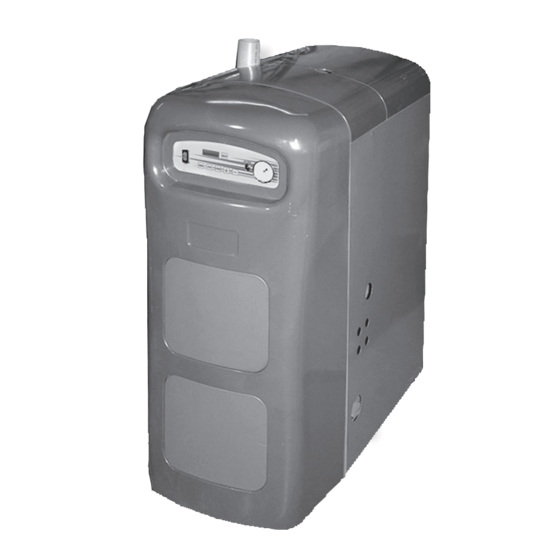
UTICA BOILERS UB95M-200 Installation, Operation & Maintenance Manual
Gas-fired direct vent modulating hot water boiler
Hide thumbs
Also See for UB95M-200:
- Installation, operation & maintenance manual (52 pages) ,
- Installation manual (48 pages)
Table of Contents
Advertisement
Advertisement
Table of Contents

Subscribe to Our Youtube Channel
Related Manuals for UTICA BOILERS UB95M-200


Summary of Contents for UTICA BOILERS UB95M-200
- Page 1 UB95M-200 Gas-Fired Direct Vent Modulating Hot Water Boiler Model INSTALLATION, OPERATION & UB95M-200 MAINTENANCE MANUAL Manufactured by: ECR International, Inc. 2201 Dwyer Avenue, Utica NY 13501 web site: www.ecrinternational.com An ISO 9001-2008 Certified Company P/N# 240006103U, Rev. E [02/2014]...
-
Page 2: Dimensions
1 - DIMENSIONS OPENING FOR SAFETY RELIEF VALVE 30⅞” 18” DISCHARGE PIPE (785mm) (458mm) 39⅜” (1.1m) -
Page 3: Table Of Contents
2 - INTRODUCTION 1 - Dimensions ......................2 2 - Introduction ......................3 3 - Important Safety Information ..................4 4 - Boiler Ratings & Capacities ..................5 5 - Before Installing The Boiler ..................6 6 - Locating The Boiler ....................7 7 - Near Boiler Piping .....................9 8 - Combustion Air And Vent Pipe .................. -
Page 4: Important Safety Information
3 - IMPORTANT SAFETY INFORMATION 3.1 General 3.2 Installation shall conform to requirements of Boiler installation shall be completed by qualified agency. authority having jurisdiction or in absence of such See glossary for additional information. requirements: • United States WARNING •... -
Page 5: Boiler Ratings & Capacities
4 - BOILER RATINGS & CAPACITIES TABLE 1: SEA LEVEL RATINGS - NATURAL AND PROPANE GASES Heating Capacity Net AHRI Rating Input (MBH) AFUE Flue Diameter Shipping Wt. (MBH) (MBH) (1)(2) High Fire 92.5% 2” CPVC & 3” PVC 284 lbs. Low Fire 1 MBH = 1,000 BTUH (British Thermal Units Per Hour) Heating Capacity and AFUE (Annual Fuel Utilization Efficiency) are based on DOE (Department of Energy) test procedures. -
Page 6: Before Installing The Boiler
5 - BEFORE INSTALLING THE BOILER 5.1 Before Boiler Installation 5.2 Boiler Sizing • Verify you have selected boiler with proper capacity Boiler is equipped for residential installations. If before continuing installation. AHRI Rating of selected used for commercial applications, additional code boiler should be greater than or equal to calculated requirements must be adhered to for installation. -
Page 7: Locating The Boiler
6 - LOCATING THE BOILER 6.1 Locating the Boiler TABLE 3: BOILER CLEARANCES Place crated boiler as close to selected location as Combustible Accessibility/ Dimension Service possible and un-crate boiler. Boiler may be moved into Construction Cleaning position with appliance dolly or 2 wheel hand truck. 1”... -
Page 8: Removal Of Existing Boiler From Common Vent System
6 - LOCATING THE BOILER 6.2 Combustion Air and Vent Pipe Requirements 6.4 Removal of Existing Boiler From Common Vent System • This boiler requires dedicated direct vent system. When an existing boiler is removed from a common • In direct vent system all air for combustion is taken venting system, the common venting system is likely to be directly from outside atmosphere, and all flue products too large for proper venting of the appliances remaining... -
Page 9: Near Boiler Piping
7 - NEAR BOILER PIPING 7.1 Clean System First 7.2 Supply & Return Lines Before connecting boiler to heating system, clean and flush See Appendix A for piping examples. system thoroughly. Verify system is free of sediment, flux • Packaged boiler set to receive 1¼” NPT return piping and any residual boiler water additives. - Page 10 7 - NEAR BOILER PIPING 7.3 Safety Relief Valve / Temperature Pressure Gauge Figure 2 - Safety Relief Valve Discharge Piping WARNING Safety Relief Valve Burn and scald hazard. Safety relief valve could discharge steam or hot water during operation. Install discharge piping per these instructions.
-
Page 11: Condensate Drain Piping
7 - NEAR BOILER PIPING 7.5 Condensate Drain Piping 7.7 Chilled Water Piping Boiler is factory equipped with a condensate trap. Install Boiler, when used in connection with refrigeration Additional trap is not required and should NOT be used. system, so chiller medium is piped in parallel with boiler with appropriate valves to prevent chilled medium from •... -
Page 12: Combustion Air And Vent Pipe
8 - COMBUSTION AIR AND VENT PIPE 8.1 Connections And Termination Maximum Allowable Temperatures Boilers for connection to gas vents or chimneys, vent TABLE 4 Of Typical Non-Metallic Vent Material installations shall be in accordance with “Venting of Equipment” of the National Fuel Gas Code, ANSI Z223.1/ Standard Material °F... - Page 13 8 - COMBUSTION AIR AND VENT PIPE 8.2 Vent/Air Intake Termination Location WARNING Consider following when determining appropriate location Covering non-metallic vent pipe and fittings with for termination of combustion air and vent piping. thermal insulation shall be prohibited. A. Position termination where vent vapors will not damage plants/shrubs, air conditioning equipment, or siding on the house.
- Page 14 8 - COMBUSTION AIR AND VENT PIPE Figure 5 - Side Wall Vent / Intake terminations - Less Than 12” Clearance Above Grade 3” MIN SEPARATION...
- Page 15 8 - COMBUSTION AIR AND VENT PIPE Figure 6 -Roof Vent / Intake Terminations 3” MINIMUM SEPARATION Figure 7 - Concentric Vent Terminations 1" (26mm) Roof Overhang Maximum 1" (26mm) Maximum 12" (300mm) Minimum * See Note 36"(915mm) Minimum Below Maintain 12"(300mm) Vent clearance above highest...
- Page 16 8 - COMBUSTION AIR AND VENT PIPE Figure 8 - Concentric Vent w/ Dimensions 8.3 Installation When transitioning from CPVC to PVC use Weld-On CPVC 724 or other cement approved for CPVC to PVC. In Canada ULC S636 approved cement must be used. Recommend all pipes be cut, prepared, and pre- assembled before permanently cementing any joint.
-
Page 17: Gas Supply Piping
9 - GAS SUPPLY PIPING 9.2 Connecting Gas Piping CAUTION WHAT TO DO IF YOU SMELL GAS Boiler is equipped with ½” NPT connection on gas valve for supply piping and ½” NPT ball valve for manual shut off. • Do not try to light any appliance. Following rules apply: •... - Page 18 9 - GAS SUPPLY PIPING DANGER Figure 10 - Gas Piping Fire Hazard. Do not use matches, candles, open flames, or other methods providing ignition source. Failure to comply will result in death or serious injury. 9.3 Leak Check Gas Piping After making gas connections, open manual shutoff valve(s) and check all gas connections for leaks before placing boiler in operation.
-
Page 19: Electrical Wiring
10 - ELECTRICAL WIRING WARNING Figure 11 - Line Voltage Monitor Electrical shock hazard. Turn OFF electrical power supply at service panel before making electrical connections. Failure to do so could result in death or serious injury. 10.1 Codes Electrically bond boiler to ground in accordance with requirements of authority having jurisdiction. - Page 20 10 - ELECTRICAL WIRING 10.6 Thermostat AVOID THE FOLLOWING Connect room thermostat or end switch (isolated Corners contact only) between terminals T1 and T2. Dead Spots Alcoves Install thermostat on inside wall away from influences Behind doors of drafts, hot or cold water pipes, lighting fixtures, televisions, sun rays, or fireplaces.
-
Page 21: Controls And Accessories
11 - CONTROLS AND ACCESSORIES Refer to Repair Parts Manual for illustrations, and Control • Gas controls perform all functions required to safely Manual and Troubleshooting Guide for detailed sequence of regulate gas flow to main burner of boiler. operation and troubleshooting guide. •... -
Page 22: Drain Valve
11 - CONTROLS AND ACCESSORIES 11.15 Blocked Vent Safety Assembly • High limit control is mounted in ½” NPT control well and ¾” X ½” bushing on top of front boiler section at Blocked vent safety assembly incorporates two pressure hot water outlet. -
Page 23: Boiler Startup
12 - BOILER STARTUP Water Treatment And Freeze Protection - See Systems With Conventional Closed Type Expansion Tanks Appendix B A. Close all zone service valves on supply and return piping and close expansion tank service valve. 12.1 Filling Boiler With Water And Purging Air Drain expansion tank. -
Page 24: Operating Instructions
13 - OPERATING INSTRUCTIONS CAUTION WHAT TO DO IF YOU SMELL GAS WARNING • Do not try to light any appliance. If you do not follow these instructions • Do not touch any electrical switches; do not use exactly, a fire or explosion may result any phone in your building. -
Page 25: Maintenance And Cleaning
14 - MAINTENANCE AND CLEANING Acidic nature of flue gases condensing on aluminum boiler 14.2 Daily During Heating Season sections cause formation of aluminum oxide. This oxide Check for and remove any obstruction to flow of formation is normal, and represents negligible mass of combustion air or venting of flue gases. - Page 26 14 - MAINTENANCE AND CLEANING G. Aluminum oxide deposits are water soluble and WARNING may be rinsed away by inserting hose into burner Following service procedures must be performed by opening of casting and slowly run water through qualified service agent. Boiler owner shall not attempt flue side of boiler and out condensate drain.
-
Page 27: Appendix A - Boiler Piping And Wiring
APPENDIX A - BOILER PIPING AND WIRING Electrical Wiring Diagram... - Page 28 APPENDIX A - BOILER PIPING AND WIRING Boiler Control Wiring Diagram: Single Zone System With Domestic Hot Water Priority BOILER CONTROL PANEL CH T1 120 VAC T-STAT CH T2 CH C1 DHW T1 CH C2 DHW T2 DHW C1 DHW C2 CIRC OUTDOOR AIR SENSOR...
- Page 29 APPENDIX A - BOILER PIPING AND WIRING Piping Diagram 1: Single Zone System With Domestic Hot Water Priority NOTE: NOT RECOMMENDED FOR ANTIFREEZE APPLICATIONS Wiring Diagram 1 : Single Zone System With Domestic Hot Water Priority Hotline indirect water heater aquastat or thermostat Boiler Control Panel T-STAT...
- Page 30 APPENDIX A - BOILER PIPING AND WIRING Piping Diagram 2 : Multizone Piping With Zone Valves And Domestic Hot Water Priority (With Zone Valve) NOTE: NOT RECOMMENDED FOR ANTIFREEZE APPLICATIONS...
- Page 31 APPENDIX A - BOILER PIPING AND WIRING Wiring Diagram 2: Multizone Wiring With Zone Valves And Domestic Hot Water Priority (With Zone Valve) SWITCH LEGEND INDIRECT WATER TANK HEATER AQUASTAT CONTROL OR THERMOSTAT T-STAT T-STAT ARGO AZ-4CUP CONTROL Yellow 24VAC Yellow STATUS PRIORITY ON...
- Page 32 APPENDIX A - BOILER PIPING AND WIRING Piping Diagram 3 : Multizone System With Zone Valves And Domestic Hot Water Priority (With Circulator) NOTE: NOT RECOMMENDED FOR ANTIFREEZE APPLICATIONS...
- Page 33 APPENDIX A - BOILER PIPING AND WIRING SWITCH LEGEND INDIRECT WATER TANK HEATER AQUASTAT CONTROL OR THERMOSTAT T-STAT T-STAT ARGO AZ-4CP CONTROL Yellow 24VAC Yellow STATUS PRIORITY ON PRIMARY PUMP PRIORITY PUMP ZONE VALVE/PUMP X-X CONTACT ZR ON PRIORITY ZC ON ZR-ZC Black DPM-2...
- Page 34 APPENDIX A - BOILER PIPING AND WIRING Piping Diagram 4: Multizone System With Circulators And Domestic Hot Water Priority NOTE: NOT RECOMMENDED FOR ANTIFREEZE APPLICATIONS...
- Page 35 APPENDIX A - BOILER PIPING AND WIRING Wiring Diagram 4: Multizone System With Circulators And Domestic Hot Water Priority Hotline indirect water heater aquastat or thermostat NOTE: IN PLACE OF 115 T-STAT VOLT ISOLATION RELAY, T-STAT OPTIONAL CONTROL T-STAT ARGO AR822II THERMOSTATS TERMINAL 5 &...
- Page 36 APPENDIX A - BOILER PIPING AND WIRING Piping Diagram 5 : Primary/Secondary Piping With Circulators And Domestic Hot Water MAX = 4 X DIAMETER CLOSELY - SPACED TEES BOILER PUMP *SEE NOTE NOTE: RECOMMENDED FOR ANTIFREEZE APPLICATIONS...
- Page 37 APPENDIX A - BOILER PIPING AND WIRING Wiring Diagram 5 : Primary/Secondary Wiring With Circulators And Domestic Hot Water INDIRECT HOT WATER HEATER AQUASTAT OR THERMOSTAT NOTE: IN PLACE OF 115 VOLT ISOLATION RELAY, OPTIONAL CONTROL ARGO AR822II TERMINAL 5 & 6 N.O. TO DHW T1 &...
- Page 38 APPENDIX A - BOILER PIPING AND WIRING Piping Diagram 6 : Primary/Secondary Multizone System Piping With Zone Valves And Domestic Hot Water (With Zone Valve) ZONE 1 (PRIORITY ZONE)* * USE FULL PORT ZONE VALVE. FOR OPTIMUM TANK PERFORMANCE, CONSIDER USING ZONE CIRCULATOR.
- Page 39 APPENDIX A - BOILER PIPING AND WIRING Wiring Diagram 6 : Primary/Secondary Multizone System Wiring With Zone Valves And Domestic Hot Water (With Zone Valve) INDIRECT WATER SWITCH LEGEND TANK HEATER AQUASTAT CONTROL OR THERMOSTAT T-STAT T-STAT ARGO AZ-4CP CONTROL Yellow Yellow STATUS...
- Page 40 APPENDIX A - BOILER PIPING AND WIRING Piping Diagram 7 : Primary/Secondary Piping With Zone Valves And Domestic Hot Water (With Circulator) ZONE VALVE MAX = 4 X DIAMETER CLOSELY - SPACED TEES *SEE NOTE NOTE: RECOMMENDED FOR ANTIFREEZE APPLICATIONS...
- Page 41 APPENDIX A - BOILER PIPING AND WIRING Wiring Diagram 7 : Primary/Secondary Piping With Zone Valves And Domestic Hot Water (With Circulator) INDIRECT WATER HEATER AQUASTAT SWITCH LEGEND TANK OR THERMOSTAT CONTROL T-STAT T-STAT ARGO AZ-4CP CONTROL Yellow Yellow STATUS PRIORITY ON PRIMARY PUMP PRIORITY PUMP...
- Page 42 APPENDIX A - BOILER PIPING AND WIRING Piping Diagram 8 : Bypass Piping (Automatic Mixing Valve) TO SYSTEM FROM SYSTEM WATER INLET EXPANSION TANK BOILER ALTERNATE CIRCULATOR LOCATION PRESSURE BALL VALVE AIR SEPARATOR CIRCULATOR REDUCER VALVE Piping Diagram 9 : Bypass Piping (Fixed Low Temp Only) SHUT-OFF 3 WAY MIXING CHECK VALVE...
- Page 43 APPENDIX A - BOILER PIPING AND WIRING Piping Diagram 10 : Bypass Piping (4-Way Valve Option With Circulator On Supply) TO SYSTEM FROM SYSTEM WATER INLET EXPANSION TANK BOILER ALTERNATE CIRCULATOR LOCATION PRESSURE Piping Diagram 11 : Multiple Boiler Piping BALL VALVE AIR SEPARATOR CIRCULATOR...
- Page 44 APPENDIX A - BOILER PIPING AND WIRING Wiring Diagram 9: Multiple Boiler Wiring (AMB-4) AMB-4 WATER SENSOR OUTSIDE SENSOR IF USING EXTERNAL DAY/NIGHT FEATURE CONNECT HERE (DRY CONTACT) IF USING REQ/ACK CONNECT HERE (TT/THERMOSTAT DRY CONTACT) TO PRIORITY IF USING (DRY CONTACT) CH T1 CH T2...
-
Page 45: Appendix B - Water Quality, Water Treatment And Freeze Protection
APPENDIX B - WATER QUALITY, WATER TREATMENT AND FREEZE PROTECTION WARNING Install boiler so gas ignition system components are protected from water (dripping, spraying, rain, etc) during appliance operation and service (circulator replacement, etc). • DIELECTRIC ISOLATION Two (2) 1-1/4” X 1-1/4” Female to female dielectric isolation unions are shipped loose in boiler parts bag. - Page 46 APPENDIX B - WATER QUALITY, WATER TREATMENT AND FREEZE PROTECTION System and Operating Precautions Applies to ALL Aluminum High Efficiency Gas-Fired Water Boilers Clean System First Eliminate System Leaks BEFORE connecting boiler to heating system, clean and Continuous addition of make-up water will constantly add flush system thoroughly.
- Page 47 APPENDIX B - WATER QUALITY, WATER TREATMENT AND FREEZE PROTECTION System and Operating Precautions Applies to ALL Aluminum High Efficiency Gas-Fired Water Boilers General Guidelines When Using Antifreeze • Use only antifreeze products recommended • It is recommended that pH reading be taken for use with aluminum boilers, as listed in annually, and adjusted as necessary.
- Page 48 APPENDIX B - WATER QUALITY, WATER TREATMENT AND FREEZE PROTECTION System and Operating Precautions Applies to ALL Aluminum High Efficiency Gas-Fired Water Boilers Antifreeze Products Table 1 Compatible Aluminum Antifreeze & Inhibitor Suppliers Noble Company P. O. Box 350 Grand Haven, MI 49417 Noburst AL Antifreeze www.noblecompany.com Tel:...
- Page 49 NOTES...
- Page 50 NOTES...
- Page 51 SERVICE RECORD...
- Page 52 • This boiler is part of a modular or multiple boiler system having a total input of 300,000 BTU/hr or greater. • This boiler is equipped with a tankless coil. UTICA BOILERS 2201 Dwyer Avenue Utica NY 13501 web site: www.ecrinternational.com...
Need help?
Do you have a question about the UB95M-200 and is the answer not in the manual?
Questions and answers