Table of Contents
Advertisement
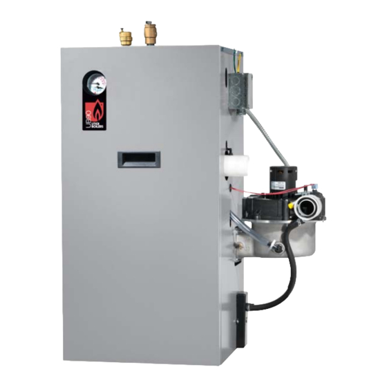
Models
UB90-50
UB90-75
UB90-100
An ISO 9001-2008 Certified Company
UB90-50/75/100 Series 4
GAS-FIRED, DIRECT VENT,
CONDENSING,
HOT WATER BOILER
INSTALLATION, OPERATION &
MAINTENANCE MANUAL
Manufactured by:
ECR International, Inc.
2201 Dwyer Avenue, Utica NY 13504-4729
web site: www.ecrinternational.com
P/N# 240010135 Rev. C [05/2013]
Advertisement
Table of Contents
Troubleshooting

Related Manuals for UTICA BOILERS UB90-50


Summary of Contents for UTICA BOILERS UB90-50
- Page 1 UB90-50/75/100 Series 4 GAS-FIRED, DIRECT VENT, Models CONDENSING, UB90-50 HOT WATER BOILER UB90-75 UB90-100 INSTALLATION, OPERATION & MAINTENANCE MANUAL Manufactured by: ECR International, Inc. 2201 Dwyer Avenue, Utica NY 13504-4729 web site: www.ecrinternational.com P/N# 240010135 Rev. C [05/2013] An ISO 9001-2008 Certified Company...
-
Page 2: Dimensions
DIMENSIONS Figure 1 - Boiler Dimensions NOTICE Draft inducer (blower) may be rotated 90° or 180° to orient vent connection towards right side or rear. -
Page 3: Table Of Contents
INTRODUCTION Dimensions ........................2 Introduction ........................3 Important Safety Information ................... 4 Boiler Ratings & Capacities ....................5 Boilers For Use At High Altitude - United States Installations ..........6 Before Installing The Boiler ....................8 Boiler Installation ......................9 Near Boiler Piping ......................11 Combustion Air And Vent Pipe .................. -
Page 4: Important Safety Information
IMPORTANT SAFETY INFORMATION General Installation shall conform to requirements of authority having jurisdiction or in absence of such Boiler installation shall be completed by qualifi ed agency. requirements: See glossary for additional information. • United States WARNING • National Fuel Gas Code, ANSI Z223.1/NFPA 54. Fire, explosion, asphyxiation and electrical shock •... -
Page 5: Boiler Ratings & Capacities
BOILER RATINGS & CAPACITIES Table 1 - SEA LEVEL RATINGS – NATURAL AND PROPANE GASES Input ++ Heating Capacity Net AHRI Rating Shipping Model AFUE *(MBH) *(MBH) Weight (lbs.) *(MBH) 90-50 90.0 90-75 90.0 90-100 90.0 * 1 MBH = 1,000 Btuh Btuh = British Thermal Units Per Hour ++ AFUE (Annual Fuel Utilization Effi... -
Page 6: Boilers For Use At High Altitude - United States Installations
BOILERS FOR USE AT HIGH ALTITUDE - UNITED STATES INSTALLATIONS • Boilers (with exception of 90-75 propane (LP) product) • Instructions on how to adjust gas manifold pressure are factory equipped for operation at altitudes ranging settings see Figure 25 and Figure 26, Page 44 . from 0-10,000 feet above sea level. - Page 7 BOILERS FOR USE AT HIGH ALTITUDE - UNITED STATES INSTALLATIONS Model 90-75 propane (LP) units only at altitudes above 5,000 ft., install 90-75 High Altitude Orifi ce Kit #550002629*. For all other altitudes use sea level orifi ce Table 3 - PROPANE GAS MODEL 90-50 Stock Factory Btu Value of Propane Gas++...
-
Page 8: Before Installing The Boiler
BEFORE INSTALLING THE BOILER Boiler is equipped for residential installations. If used Boiler Sizing for commercial applications, any additional code Check to be sure you have selected boiler with proper requirements must be adhered to for installation. capacity before starting installation. AHRI Rating of boiler This may require additional controls including but not selected should be greater than or equal to calculated limited to an additional low water cut off, a manual... -
Page 9: Boiler Installation
BOILER INSTALLATION Locating The Boiler Combustion Air And Vent Pipe Requirements Place crated boiler as close to selected location as This boiler requires a dedicated direct vent system. In a possible and un-crate boiler. Boiler may be moved into direct vent system, all air for combustion is taken directly position with appliance dolly or 2 wheel hand truck. - Page 10 BOILER INSTALLATION Condensate Drain Requirements In-so-far as is practical, close all building doors and windows and all doors between the space in which the • Pitch condensate drain line down to fl oor drain at appliances remaining connected to the common venting minimum of ¼”...
-
Page 11: Near Boiler Piping
NEAR BOILER PIPING Near Boiler Piping Supply And Return Lines • When boiler installation is for new heating system, • Boiler is set up to receive 1¼” NPT supply and return install all of radiation units (panels, radiators, piping from top access. baseboard, or tubing) and supply and return mains. - Page 12 NEAR BOILER PIPING Figure 2 - Single Zone Boiler Piping SAFETY RELIEF VALVE - SEE PAGE 18 FOR REQUIREMENTS...
- Page 13 NEAR BOILER PIPING Multi-Zone Systems Multi-zone systems with two zones are typically piped as shown in Figures 3 or 4. Multi-zone systems with more than two zones are likely to have small zones with very low heat and fl ow requirements compared to full heating capacity of the boiler.
- Page 14 NEAR BOILER PIPING Figure 4 - Two Zone Boiler Piping With Circulators SAFETY RELIEF VALVE - SEE PAGE 18 FOR REQUIREMENTS...
- Page 15 NEAR BOILER PIPING Figure 5 - Primary/Secondary Piping With Circulators And Domestic Hot Water...
- Page 16 NEAR BOILER PIPING Figure 6 - Piping Primary/Secondary Multi Zone System Piping With Zone Valves And Domestic Hot Water (With Zone Valve)
- Page 17 NEAR BOILER PIPING Figure 7 - Piping Primary/Secondary Piping With Zone Valves And Domestic Hot Water (With Circulator)
- Page 18 NEAR BOILER PIPING WARNING Figure 8 - Relief Valve Boiler Piping Burn and scald hazard. Safety relief valve could discharge steam or hot water during operation. RELIEF VALVE Install discharge piping per these instructions. DISCHARGE Safety Relief Valve LINE Installation of safety relief valve shall conform to ANSI/ ASME Boiler and Pressure Vessel Code, Section IV.
- Page 19 NEAR BOILER PIPING Figure 9 - Diaphragm Type Expansion Tank Piping SAFETY RELIEF VALVE - SEE PAGE 18 FOR REQUIREMENTS...
- Page 20 NEAR BOILER PIPING Figure 10 - Conventional (Closed Type) Expansion Tank Piping SAFETY RELIEF VALVE SEE PAGE 18 FOR REQUIREMENTS...
-
Page 21: Condensate Drain Piping
NEAR BOILER PIPING Condensate Drain Piping Filling Condensate Trap With Water Boiler is factory equipped with a condensate trap. An On initial start up condensate trap must be manually fi lled additional trap is not required and should NOT be used. with water. -
Page 22: Combustion Air And Vent Pipe
COMBUSTION AIR AND VENT PIPE Connections And Termination Canadian installations: • First 3 feet (900mm) of venting must be readily Provisions for combustion and ventilation air must be available for visual inspection. in accordance with section, Air For Combustion and Ventilation, of the National Fuel Gas Code,ANSI 2223.1/ •... - Page 23 COMBUSTION AIR AND VENT PIPE Table 5 - Combustion Air And Vent Piping Lengths - Total Equivalent Length 2” PIPE MINIMUM 2” PIPE MAXIMUM 3” PIPE MINIMUM 3” PIPE MAXIMUM BOILER VENTING VENTING VENTING VENTING SIZE 2 FEET 21 FEET 15 FEET 92 FEET 2 FEET...
- Page 24 COMBUSTION AIR AND VENT PIPE Installation Wipe excess cement from joint. Continuous bead of cement will be visible around perimeter of properly Attach combustion air intake piping using fi eld supplied made joint. 2” fl exible coupling. Attach vent piping to furnished 2” Handle pipe joint carefully until cement sets.
- Page 25 COMBUSTION AIR AND VENT PIPE Figure 13 - Side Wall Vent / Intake terminations - Less Than 12” Clearance Above Grade OVERHANG Less Than 12” Clearance 12" MINIMUM 12" MINIMUM 12" SEPARATION 12" BETWEEN BOTTOM MINIMUM OF AIR INTAKE AND BOTTOM OF VENT 90°...
- Page 26 COMBUSTION AIR AND VENT PIPE Figure 17 - Concentric Vent Roof Figure 15 - Concentric Vent Terminations Installation 1" (25.4mm) Maximum Vent Combustion 1" (25.4mm) Overhang Maximum 12" (305mm) Minimum * See Note 36"(0.9m) Minimum Below Maintain 12" Maintain US 12"(305mm) clearance above Vent Canada 18”...
- Page 27 COMBUSTION AIR AND VENT PIPE Figure 18 - Combustion Air and Vent Piping - Boiler Connections SAFETY RELIEF VALVE SEE PAGE 18 FOR REQUIREMENTS 2” (50.8mm) Diameter Vent And Combustion Air Intake Piping - 21 ft (6.4m)maximum total equivalent length for 90-100 models -26 ft (7.9m) maximum total equivalent length for 90-50 and -90-75 models...
-
Page 28: Gas Supply Piping
GAS SUPPLY PIPING CAUTION DANGER WHAT TO DO IF YOU SMELL GAS Fire Hazard. Do not use matches, candles, open fl ames, or other methods providing ignition source. • Do not try to light any appliance. Failure to comply will result in death or serious •... - Page 29 GAS SUPPLY PIPING Table 7 – Gas Pipe Sizes NATURAL GAS Pipe Capacity - BTU Per Hour Input Includes Fittings Length of 1/2” 3/4” 1” 1 1/4” Pipe - Ft. 92,000 190,000 350,000 625,000 63,000 130,000 245,000 445,000 50,000 105,000 195,000 365,000 PROPANE GAS...
-
Page 30: Electrical Wiring
ELECTRICAL WIRING Connect Circulator Pump Wiring WARNING See Figure 20, Page 31 for circulator pump fi eld wiring Electrical shock hazard. Turn OFF electrical power connections. supply at service panel before making electrical Supplied 5 foot wiring harness with fl exible metal conduit connections. - Page 31 ELECTRICAL WIRING Figure 20 - Field Wiring Connections SAFETY RELIEF VALVE SEE PAGE 18 FOR REQUIREMENTS...
- Page 32 ELECTRICAL WIRING Figure 21 - Wiring Schematic NOTICE If any of original wire as supplied with this appliance must be replaced, it must be replaced with type 105°C Thermoplastic wire or its equivalent...
- Page 33 ELECTRICAL WIRING Figure 22 - Ladder Diagram for Figure 22...
-
Page 34: Controls And Accessories
CONTROLS AND ACCESSORIES A - Setting High Limit 1 - Integrated Boiler Control (IBC) • Integrated Boiler Control (IBC) is a microprocessor To adjust, turn HI TEMP dial until desired setting based controller for high effi ciency gas boilers. is displayed. Overall range of High limit setting is from 100°F to 220°F (82°... -
Page 35: Hot Surface Igniter
CONTROLS AND ACCESSORIES 7 - Differential Pressure Air Proving Switch/ SETTING Blocked Vent Safety Shutoff Disables economy function. Will allow boiler to fi re Differential pressure switch monitors air fl ow by sensing until hi-limit temp is reached and re-fi re with a 10° differential pressure measured in inches of water (”... -
Page 36: Start Up
START UP Water Quality, Water Treatment and Freeze Control - System Startup Protection - see Appendix A At initial start up, with the Economy feature active, the control establishes a 145°F target temperature. To test the high limit shut-off function, the Economy dial must be Filling Boiler With Water And Purging Air For turned to OFF. -
Page 37: Operating Instructions
OPERATING INSTRUCTIONS WARNING CAUTION If you do not follow these instructions WHAT TO DO IF YOU SMELL GAS exactly, a fi re or explosion may result causing • Do not try to light any appliance. property damage, personal injury or loss of life. -
Page 38: Detailed Sequence Of Operation
DETAILED SEQUENCE OF OPERATION SERVICE HINTS POWER ON STAND BY THERMOSTAT CALLS FOR HEAT IF MAIN BURNER DOES NOT PROVE FLAME IN 3 TRIALS, CONTROL LOCKOUT. VALVE/FLAME LIGHT BLINKS , CIRCULATOR RESET IS REQUIRED. THIS PROBLEM IS A ENERGIZES THRU RESULT OF NOT ESTABLISHING FLAME SIGNAL. - Page 39 DETAILED SEQUENCE OF OPERATION End Of Normal Sequence Of Operation Thermostat ends call for heat. Gas valve and circulator pump are de-energized, valve and fl ame lights go out. Blower runs for 30 seconds post purge, purge light is on. Blower is de-energized after 30 seconds, purge light shuts off.
- Page 40 DETAILED SEQUENCE OF OPERATION Sequence Of Operation Diagnostics Follow sequence using the diagnostic indicator lamps on Integrated Boiler Control (IBC). See “Controls And Accessories” on page 34 for normal sequence of operation. Detailed sequence of operation containing potential faults can be found in service hints section.
- Page 41 DETAILED SEQUENCE OF OPERATION DRAFT INDUCER TEMPERATURE SAFETY CASTING TEMPERATURE SAFETY SWITCH SWITCH If burner operates when boiler has no water, If draft inducer temperature reaches temperature aluminum boiler sections heat up rapidly. safety switch set-point, safety switch contacts open immediately, closing gas valve (light goes out) Casting temperature safety switch contacts will...
-
Page 42: Verifi Cation Procedure And Adjustment
VERIFICATION PROCEDURE AND ADJUSTMENT Verify Proper Sequence Of Operation Measure Natural Gas Input Rate Correct input rate is essential for proper and effi cient Place boiler into operation and observe operation through operation of the burner and boiler. several cycles. Follow remaining steps in this section to Determine elevation at installation site. - Page 43 VERIFICATION PROCEDURE AND ADJUSTMENT IV. Measure new input rate (cover screw must be installed). Repeat steps I.-IV until the input rate is within +/-2% of the nameplate input rating. V. If the actual input rate can not be set to within 2% of the correct input rating by adjusting manifold pressure, a change in gas orifi...
- Page 44 VERIFICATION PROCEDURE AND ADJUSTMENT Figure 25 - Manifold Pressure Measurement Detail Following steps and diagram indicate location of the Refer to “Differential Air Pressure Switch Check - all connection points required to measure manifold pressure. models” on page 45 when reading manifold pressure. Manifold pressure may be measured using a U-Tube When measurement is complete, disconnect U-Tube Manometer or Differential Pressure Gauge.
-
Page 45: Differential Air Pressure Switch Check - All Models
DIFFERENTIAL AIR PRESSURE SWITCH CHECK - ALL MODELS • Following steps and diagram indicate locations of PRESSURE connection points required to check differential air BOILER DIFFERENTIAL SWITCH pressure. STATUS PRESSURE (W.C.) CONTACTS • Differential air pressure switch is safety device which prevents boiler from fi... -
Page 46: Negative Pressure Switch Check
NEGATIVE PRESSURE SWITCH CHECK For use on Model - 100 boilers only. PRESSURE • Following steps and diagram indicate locations of BOILER NEGATIVE SWITCH connection points required to check negative pressure. STATUS PRESSURE (W.C.) CONNECTS • Negative pressure switch is safety device which Normally prevents boiler from fi... -
Page 47: Maintenance And Cleaning
MAINTENANCE AND CLEANING Maintenance As Outlined Below Can Be Check boiler area is free from combustible materials, gasoline, and other fl ammable vapors and liquids. Performed By Owner Unless Otherwise Noted. • The acidic nature of fl ue gasses condensing on Circulator pump and blower motor furnished with boiler aluminum boiler sections may cause formation of are permanently lubricated from factory and require no... - Page 48 MAINTENANCE AND CLEANING Annual Examination And Cleaning Of Boiler K. Reinstall burner and mixer gasket and position mixer assembly over studs. Install fi ve (5) nuts but Components do not tighten. Reinstall igniter and igniter gasket DANGER and fasten with two (2) screws. Use care when Before servicing, turn off electrical power to boiler installing the igniter.
-
Page 49: Troubleshooting
TROUBLESHOOTING Troubleshooting tools: WARNING A. Voltmeter to check 120 vac and 24 vac Fire, explosion or shock hazard. Do not attempt to B. Continuity tester. modify the physical or electrical characteristics of C. Inclined manometer or pressure gauge with this boiler in any way. Failure to comply could result 0-3.0”... -
Page 50: Troubleshooting - High Limit Control And Lwco
TROUBLESHOOTING - HIGH LIMIT CONTROL AND LWCO LED Legend and LWCO Test Button Figure 27 - LED Legend HI TEMP illuminates when boiler water temperature reaches high limit setting. Remains lit until water temperature falls 10°F below high limit setting. Limit prevents burner operation while this LED is on. -
Page 51: Troubleshooting -Hydrostat High Limit Control And Lwco
TROUBLESHOOTING -HYDROSTAT HIGH LIMIT CONTROL AND LWCO Troubleshooting Flow Chart Burner Will Not Fire See Flow Chart, this page. If installed with indirect water heater, insure end switch in relay box controlling indirect water No or Insuffi cient heater is properly connected to Cable 2. This will insure domestic water calls are prioritized. If Domestic Hot Water Cable 2 is not used, turn Economy Feature OFF. - Page 52 TROUBLESHOOTING Troubleshooting Chart 1...
- Page 53 TROUBLESHOOTING Troubleshooting Chart 2...
- Page 54 TROUBLESHOOTING Troubleshooting Chart 3 CHART 1 OPEN CHECK FOR VAC BLOWER STARTS BETWEEN TERMINALS 1 AND 3 REPLACE IBC AT CONNECTOR CN4 ON IBC CHECK FOR 120 VAC AT REPAIR/REPLACE BLOWER LEADS ON WIRING WIRING FROM IBC HARNESS TO BLOWER REPAIR/REPLACE BLOWER PRESSURE SWITCH...
- Page 55 TROUBLESHOOTING Troubleshooting Chart 4 CHART 3 CHECK FOR 120 VAC IGNITER/SENSOR WARMS BETWEEN TERMINALS 1 UP AND GLOWS AND 2 AT CONNECTOR REPLACE IBC YELLOW/ORANGE CN1 ON IBC (DURING DURING 20 SECOND IGNITER WARM UP) WARM UP CHECK FOR 120 VAC AT IGNITER/SENSOR LEADS REPAIR/REPLACE WIRING ON WIRING HARNESS...
- Page 56 TROUBLESHOOTING Troubleshooting Chart 5 CHART 4 CHART 4 POSSIBLY MIXTURE TOO LEAN! CHECK GAS LINES DOWNSTREAM OF GAS VALVE FOR BLOCKAGE. CLEAN/REPLACE GAS LINES . ARE GAS LINES CLEAR? BE SURE TO USE CORRECT GAS/VENTURI VALVE SIZE. IS GAS/VENTURI VALVE CORRECT SIZE? SEE REPAIR PARTS DIAGRAM.
- Page 57 TROUBLESHOOTING Troubleshooting Chart 6 CHART 5 CHART 5 CHART 5 REPLACE GAS CONTROL. NO #3 NO #2 CHECK GAS ORFICICE SIZE. IS GAS ORIFICE SIZE CORRECT. CHECK REPAIR PARTS LIST FOR CORRECT SIZE. IS GAS ORIFICE CLEAR OF BLOCKAGE. RUNS FOR 25-50 SECONDS, THEN TURNS OFF.
-
Page 58: Appendix A - Water Quality, Water Treatment And Freeze Protection
APPENDIX A - WATER QUALITY, WATER TREATMENT AND FREEZE PROTECTION Aluminum Series High Effi ciency Gas-Fired Boiler DIELECTRIC ISOLATION & ANTIFREEZE PROTECTION WARNING Follow these instructions to prevent damage to boiler’s heat exchanger caused by inadequate dielectric isolation, incorrect water treatment or antifreeze application. - Page 59 System and Operating Precautions Applies to ALL Aluminum High Effi ciency Gas-Fired Water Boilers Clean System First Eliminate System Leaks BEFORE connecting boiler to heating system, clean and Continuous addition of make-up water will constantly add fl ush system thoroughly. Verify system is free of sediment, oxygen to system.
- Page 60 System and Operating Precautions Applies to ALL Aluminum High Effi ciency Gas-Fired Water Boilers General Guidelines When Using Antifreeze • Recommend taking pH reading annually, and • Use only antifreeze products recommended adjusted as necessary. Follow antifreeze/inhibitor for use with aluminum boilers, as listed in manufacturer’s instructions for details on how to this addendum.
- Page 61 System and Operating Precautions Applies to ALL Aluminum High Effi ciency Gas-Fired Water Boilers Table 8 - Antifreeze Products Compatible Aluminum Antifreeze & Inhibitor Suppliers Noble Company P. O. Box 350 Grand Haven, MI 49417 Noburst AL Antifreeze www.noblecompany.com Tel: 800-878-5788 Fax: 231-799-8850...
-
Page 62: Installation And Check-Out Certifi Cate
INSTALLATION AND CHECK-OUT CERTIFICATE INSTALLATION AND CHECK-OUT CERTIFICATE Boiler Model Serial # Date Installed___________ Measured BTU/HR input____________ Installation instructions have been followed Checkout procedure and adjustments performed Maintenance and Service issues reviewed with owner/ maintenance person Installation booklet affi xed on or adjacent to boiler Installer (Company) Address Phone... - Page 63 NOTES...
- Page 64 UTICA BOILERS 2201 Dwyer Avenue Utica NY 13501 web site: www.ecrinternational.com...
Need help?
Do you have a question about the UB90-50 and is the answer not in the manual?
Questions and answers