Table of Contents
Advertisement
Quick Links
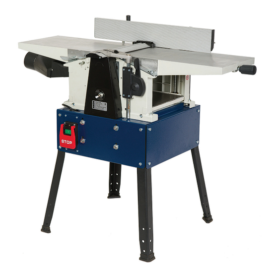
25-010
10" Planer / Jointer
4001824
Operator's Manual
Record the serial number and date of purchase in your manual for future reference.
Serial Number: _________________________
Date of purchase: _________________________
For technical support or parts questions, email techsupport@rikontools.com or call toll free at (877)884-5167
www.rikontools.com
25-010M4
Advertisement
Table of Contents
Troubleshooting

Related Manuals for Rikon Power Tools 25-010


Summary of Contents for Rikon Power Tools 25-010
- Page 1 25-010 10” Planer / Jointer 4001824 Operator’s Manual Record the serial number and date of purchase in your manual for future reference. Serial Number: _________________________ Date of purchase: _________________________ For technical support or parts questions, email techsupport@rikontools.com or call toll free at (877)884-5167 www.rikontools.com...
-
Page 2: Table Of Contents
Changes and improvements may be made at any time, with no obligation on the part of Rikon Power Tools, Inc. to modify previously delivered units. Reasonable care has been taken to ensure that the information in this manual is correct, to provide you with the guidelines for the proper safety,... -
Page 3: Safety Instructions
SAFETY INSTRUCTIONS IMPORTANT! Safety is the single most important consideration in the operation of this equipment. The following instructions must be followed at all times. Failure to follow all instructions listed below may result in electric shock, fi re, and/or serious personal injury. There are certain applications for which this tool was designed. - Page 4 SAFETY INSTRUCTIONS 12. KEEP PROTECTIVE GUARDS IN PLACE AND IN 25. ALWAYS WEAR A DUST MASK TO PREVENT WORKING ORDER. INHALING DANGEROUS DUST OR AIRBORNE PARTICLES, including wood dust, crystalline silica dust 13. AVOID ACCIDENTAL STARTING. Make sure that and asbestos dust. Direct particles away from face and the power switch is in the “OFF”...
-
Page 5: Electricals & Wiring Diagram
SAFETY INSTRUCTIONS ELECTRICAL SAFETY EXTENSION CORDS THIS TOOL MUST BE GROUNDED THE USE OF AN EXTENSION CORD WITH THIS MACHINE IS NOT RECOMMENDED. For WHILE IN USE TO PROTECT THE OPERATOR FROM ELECTRIC SHOCK. best power and safety, plug the machine directly into a dedicated, grounded electrical outlet that is within the IN THE EVENT OF A MALFUNCTION OR BREAKDOWN, supplied cord length of the machine. - Page 6 SAFETY INSTRUCTIONS SPECIFIC SAFETY INSTRUCTIONS FOR PLANER / JOINTERS This machine is intended for the surfacing of natural, solid woods. The permissible workpiece dimensions must be observed (see Technical Specification). Any other use not as specified, including modification of the machine or use of parts not tested and approved by the equipment manufacturer can cause unforeseen damage.
-
Page 7: Getting To Know Your Machine
Cutterhead Guard Height Adjustment Lever Power Cord CONTENTS OF PACKAGE Model 25-010 Planer/Jointer is shipped complete in one box. Unpacking and Clean-up 1. Carefully remove all contents from the shipping carton. Compare the contents with the list of contents to make sure that all of the items are accounted for, before discarding any packing material. -
Page 8: Installation
CONTENTS OF PACKAGE LIST OF LOOSE PARTS A. Outfeed Table B. Infeed Table C. Fence Assembly D. Legs & Floor Pads E. Dust Hood F. Depth of Cut Control Bar G. Nuts & Bolts for Leg Assembly H. Handle I. Tools a. - Wrenches - 10 & 13mm b. -
Page 9: Assembly
ASSEMBLY THE MACHINE MUST NOT BE PLUGGED IN AND THE POWER SWITCH MUST BE IN THE 'OFF' POSITION UNTIL ASSEMBLY IS COMPLETE. LEG INSTALLATION To install the legs, the machine must be placed onto its side to gain access to the underside to secure the nuts and washers. - Page 10 ASSEMBLY Installing the Infeed Table - Continued from page 9 3. Insert the bar through the table’s end hole and under- side of the table. Then re-attach the Spring Washer and Collar onto the Bar to secure it in place. FIG. 7. 4.
-
Page 11: Adjustments
ASSEMBLY THE MACHINE MUST NOT BE PLUGGED IN AND THE POWER SWITCH MUST BE IN THE 'OFF' POSITION UNTIL ASSEMBLY IS COMPLETE. OUTFEED TABLE INSTALLATION 1. Position the outfeed table onto the left end of the ma- chine frame. The two Setting Brackets (#158) fit over the pre-installed Pan Head, Location Screws (#160) on the frame for positioning, and then lock the table in place with the Levers (#233, 234). -
Page 12: Outfeed Table Adjustment
ADJUSTMENTS INFEED TABLE ADJUSTMENT INDICATOR LINE The Infeed Table is preset at the factory to be aligned with the cutterhead. To ensure that both the infeed and outfeed jointer tables are aligned, check both table settings and DEPTH SCALE adjust the outfeed table as necessary. 1. -
Page 13: Jointer Fence Adjustment
ADJUSTMENTS 4. Check the alignment of the tables with the straight edge OUTFEED on both front and rear sides of the of the tables. Make TABLE further adjustments with the guide screws as necessary, until the tables are parallel with each other. 5. - Page 14 ADJUSTMENTS PLANER HEIGHT ADJUSTMENT Height adjustment of the planer’s table is made with the Handle (#130, FIG. 22, A). One full turn of the crank changes the height of the Planer’s Table (#142, B) by 1/8”. - Clockwise Turning = raises the planer bed - Counter-Clockwise Turning = lowers the planer bed.
- Page 15 ADJUSTMENTS ADJUSTING THE PLANER TABLE THE MACHINE MUST NOT BE PLUGGED IN AND THE POWER SWITCH MUST BE IN THE 1. The planer table is attached to the cabinet and moves OFF POSITION UNTIL ALL ADJUSTMENTS ARE COMPLETE. vertically by four Threaded Spindles, or posts (#131, FIG. 24, A).
- Page 16 ADJUSTMENTS ADJUSTING DRIVE BELTS The cutterhead drive belt and the feed gear drive belts need to be checked periodically and re-tightened if nec- essary. Belts will stretch with use, especially when they are new and are breaking in. Both drive belts are located behind the machine's front and rear covers.
-
Page 17: Knife Setting
ADJUSTMENTS ON/OFF SWITCH The planer is equipped with a standard, push button ON/ START BUTTON OFF safety switch (#302, FIG. 30). Push the top green button to start the planer. There should be a ‘click’ to indi- cate the ‘on’ contact is made. Push the lower red button paddle switch to stop the planer. - Page 18 FIG. 37. NOTE: POSITION The 25-010 planer blades (#105) are reversible! Both front and back edges are sharpened. Just flip to change. 8. Place the lockbar with the mounted knife back into the 10. Perform the same procedure, steps 4-9, on the two cutterhead.
-
Page 19: Operation
OPERATION Before turning on the machine, review the safety precautions listed on pages 3 to 6. Make sure that you fully understand the features, adjustments and capabilities of the machine that are outlined throughout this manual. JOINTER OPERATION FIG. 38 The function of the jointer is to surface plane flat, one side or edge of a board/work piece. - Page 20 OPERATION Jointer Operation - Continued from page 19 against the work piece. Lock blade guard in place before 6. Turn the machine on and place the work piece on the starting the machine. Push the work piece slowly and infeed table. Feed the work piece toward the cutterhead, steady against cutterhead.
- Page 21 OPERATION Planer Operation - Continued from page 20 3. Set planing thickness. Measure your board's thickness - Make sure that there are no loose knots, nails, staples, and set the planer to this measurement, or 1/16" under this dirt or foreign objects in the wood to be planed. figure.
-
Page 22: Troubleshooting
TROUBLESHOOTING FOR YOUR OWN SAFETY, ALWAYS TURN OFF AND UNPLUG THE MACHINE BEFORE CARRYING OUT ANY TROUBLESHOOTING. SYMPTOM POSSIBLE CAUSES SOLUTIONS Machine will not start. 1. No power 1. Check power source, plug and wiring. 2. Blown fuse 2. Check fuse, replace if it is blown. 3. -
Page 23: Troubleshooting
TROUBLESHOOTING SYMPTOM POSSIBLE CAUSES SOLUTIONS TROUBLESHOOTING THE JOINTER - continued 1. Lumber has a high moisture 1. Reduce the moisture content by drying Milled surface grain is content it, or switch to other properly seasoned rough, raised or fuzzy lumber. 2. -
Page 24: Maintenance
MAINTENANCE Turn the power switch “OFF” and disconnect the plug from the outlet prior to adjusting or maintaining the machine. DO NOT attempt to repair or maintain the electrical components of the motor. Contact a qualified service technician for this type of maintenance. 6. -
Page 25: Parts Diagrams & Parts Lists
PARTS DIAGRAM & PARTS LIST MOTOR & CABINET DESCRIPTION KEY NO. DESCRIPTION RIKON PART NO. KEY NO. RIKON PART NO. Washer – 6.4mm P25-010-301 Carriage Bolt – M8 x 16mm P25-010-315 Switch P25-010-302 Motor P25-010-319 Hex Head Bolt – M8 x 16mm P25-010-303 319A Capacitor (not shown) - Page 26 PARTS DIAGRAM FRAME & TABLE ASSEMBLY...
- Page 27 PARTS LIST...
- Page 28 PARTS DIAGRAM FENCE & DRIVE ASSEMBLY...
- Page 29 PARTS LIST...
-
Page 30: Accessories
ACCESSORIES 25-910 MOBILE BASE C20-910 10” HSS KNIVES - PACK of 3 NOTES Use this section to record maintenance, service and any calls to Technical Support:... -
Page 31: Warranty
WARRANTY... - Page 32 25-010 For more information: 16 Progress Road Billerica, MA 01821 877-884-5167 / 978-528-5380 techsupport@rikontools.com www.rikontools.com 25-010M4...
Need help?
Do you have a question about the 25-010 and is the answer not in the manual?
Questions and answers