
Subscribe to Our Youtube Channel
Related Manuals for Miller HF 5000 CE


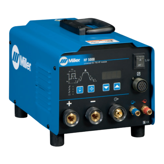
Summary of Contents for Miller HF 5000 CE
- Page 1 OM−235 241D 2015−07 Processes TIG (GTAW) Welding Stick (SMAW) Welding Description HF 5000 OWNER’S MANUAL Visit our website at www.MillerWelds.com...
- Page 2 From Miller to You Thank you and congratulations on choosing Miller. Now you can get the job done and get it done right. We know you don’t have time to do it any other way. That’s why when Niels Miller first started building arc welders in 1929, he made sure his products offered long-lasting value and superior quality.
-
Page 3: Table Of Contents
TABLE OF CONTENTS SECTION 11 − SAFETY PRECAUTIONS - READ BEFORE USING ........11-1. -
Page 4: Declaration Of Conformity
DECLARATION OF CONFORMITY for European Community (CE marked) products. ITW Welding Italy S.r.l Via Privata Iseo 6/E, 20098 San Giuliano M.se, (MI) Italy declares that the prod uct(s) identified in this declaration conform to the essential requirements and provisions of the stat ed Council Directive(s) and Standard(s). -
Page 5: Section 11 − Safety Precautions - Read Before Using
SECTION 1 − SAFETY PRECAUTIONS - READ BEFORE USING som 2013−09 Protect yourself and others from injury — read, follow, and save these important safety precautions and operating instructions. 1-1. Symbol Usage DANGER! − Indicates a hazardous situation which, if Indicates special instructions. - Page 6 D Remove stick electrode from holder or cut off welding wire at FUMES AND GASES can be hazardous. contact tip when not in use. D Wear body protection made from durable, flame−resistant material Welding produces fumes and gases. Breathing (leather, heavy cotton, wool). Body protection includes oil-free these fumes and gases can be hazardous to your clothing such as leather gloves, heavy shirt, cuffless trousers, high health.
-
Page 7: Additional Symbols For Installation, Operation, And Maintenance
1-3. Additional Symbols For Installation, Operation, And Maintenance FIRE OR EXPLOSION hazard. MOVING PARTS can injure. D Do not install or place unit on, over, or near D Keep away from moving parts such as fans. combustible surfaces. D Keep all doors, panels, covers, and guards D Do not install unit near flammables. -
Page 8: California Proposition 65 Warnings
1-4. California Proposition 65 Warnings Welding or cutting equipment produces fumes or gases This product contains chemicals, including lead, known to which contain chemicals known to the State of California to the state of California to cause cancer, birth defects, or other cause birth defects and, in some cases, cancer. -
Page 9: Section 2 − Definitions
SECTION 2 − DEFINITIONS 2-1. Additional Safety Symbols And Definitions Warning! Watch Out! There are possible hazards as shown by the symbols. Safe1 2012−05 Wear dry insulating gloves. Do not touch electrode with bare hand. Do not wear wet or damaged gloves. Safe2 2012−05 Protect yourself from electric shock by insulating yourself from work and ground. -
Page 10: Miscellaneous Symbols And Definitions
Do not weld on drums or any closed containers. Safe16 2012−05 Do not discard product (where applicable) with general waste. Reuse or recycle Waste Electrical and Electronic Equipment (WEEE) by disposing at a designated collection facility. Contact your local recycling office or your local distributor for further information. Safe37 2012−05 Wear hat and safety glasses. - Page 11 Recycle or Dispose of used Gas Output Final Slope Time coolant in an environmentally safe way Gas Input Amps Final Gas Preflow Time Gas Postflow Note Time Amps Initial Adjust Amps Background Initial Slope Time Notes OM-235 241 Page 7...
-
Page 12: Section 3 − Specifications
SECTION 3 − SPECIFICATIONS 3-1. Serial Number And Rating Label Location The serial number and rating information for this product is located on the rear panel. Use rating label to determine input power requirements and/or rated output. For future reference, write serial number in space provided on cover of this manual. 3-2. -
Page 13: Duty Cycle And Overheating
3-4. Duty Cycle And Overheating Duty Cycle is percentage of 10 minutes that unit can weld at rated load without overheating. If unit overheats, thermostat(s) opens, output stops, and cooling fan runs. Wait fifteen minutes for unit to cool. Reduce amperage or duty cycle before welding. -
Page 14: Section 4 − Installation
SECTION 4 − INSTALLATION 4-1. Selecting Cable Sizes* NOTICE − The Total Cable Length in Weld Circuit (see table below) is the combined length of both weld cables. For example, if the power source is 30 m (100 ft) from the workpiece, the total cable length in the weld circuit is 60 m (2 cables x 30 m). Use the 60 m (200 ft) column to determine cable size. -
Page 15: Installing Gas Supply
4-2. Installing Gas Supply Turn off HF unit before making gas connec- tions Cylinder valve Remove cap, stand to side of valve, and open valve slightly. Gas flow blows dust and dirt from valve. Close valve. Regulator/Flowmeter Install so face is vertical. Flow Adjust Typical flow rate is 15 CFH (cubic feet per hour) (4.5 L/... -
Page 16: Rear Panel Receptacle Information
4-4. Rear Panel Receptacle Information Turn off power before making connections. Do not use worn, damaged, un- dersized, or repaired cables. Coolant Out Connection Connect coolant return hose to coolant out fitting. Coolant In Connection Connect coolant supply hose to coolant in fitting. -
Page 17: Typical Connection To Power Source
4-6. Typical Connection To Power Source HF 5000 Welding Power Source Cooling System Typical Interconnecting Cable Size power cables within the interconnecting cable for the required welding cur- rent and duty cycle (see Sec- tion 4-1). See welding power source Owner’s Manual, and following applicable codes when selecting cable... -
Page 18: Section 5 − Operation
SECTION 5 − OPERATION 5-1. Front Panel Controls Power (On/Off )Switch Use switch to turn unit on/off. Upon power up, unit will recall and display the last welding procedure, or fact- ory default procedure. The display on the unit will show STCK if Stick was selected last. -
Page 19: Initial Setup
5-2. Initial Setup Process Control Adjust Setup Control Decrease Control Increase Control Ammeter And Parameter Display Power Switch To enter Initial Setup, turn power off. Press and hold Increase and Decrease controls and turn power on. Continue to hold Increase and Decrease controls until software version clears display, and display begins to flash, release Increase... -
Page 20: Memory Control
5-3. Memory Control ory parameters is performed (see Sec- Press and hold Decrease control until STO The first three alphanumeric digits of tion 5-4). is displayed. the display indicate the desired action Process Control Press Increase control to select desired being requested for the selected memory position 0−9. -
Page 21: Resetting Unit To Factory Default Settings
5-4. Resetting Unit To Factory Default Settings Document all welding parameters each memory position. This procedure will delete operator specified parameters, and recall all factory parameters.. Process Control Increase Control Ammeter And Parameter Display Power Switch Turn unit off. Press and hold- ing the Process and Increase controls, turn unit on, wait for CLR to display before releas-... -
Page 22: Or 4T Trigger Mode Selection
5-6. 2T Or 4T Trigger Mode Selection Document all welding parameters each memory position. Process Control Decrease Control Increase Control Ammeter And Parameter Display Power Switch Turn unit on. When welding with any TIG process, the unit will first display 2T of 4T. To change between 2T and 4T, press the Process control and 2T or 4T will display. -
Page 23: Process Control
5-7. Process Control Ammeter And Parameter Display Process Control Process LEDs Press Process control until desired process LED or com- bination of LEDs are illumin- ated: L1 − Stick welding (SMAW) L2 − TIG Lift Start − when se- lected, is an arc starting meth- od in which the electrode must come in contact with the work- piece to initiate an arc ( see... -
Page 24: Pulse Control
5-8. Pulse Control Pulse welding is only available while using the TIG process. Pulse Control LEDs Setup Control Decrease Control Increase Control Ammeter And Parameter Display While pulse welding, the cur- rent is alternating between a peak current (A) and a back- ground current (Ab), with a defined percent (%) of peak current, and a defined fre-... -
Page 25: Sequence Control
5-9. Sequence Control Sequencing is only available while using a TIG process. Sequence LEDs Sequencing is available only while using the TIG process, but is disabled if a remote foot or finger current control is connected to the remote receptacle. Sequencer parameters cannot be selected if the stick process is act- ive. -
Page 26: Lift-Arc™ And Hf Tig Start Procedures
5-10. Lift-Arc™ And HF TIG Start Procedures Lift-Arc Start When Lift-Arct button light is On, start arc as follows: TIG Electrode Lift-Arc Start Method Workpiece Touch tungsten electrode to workpiece at weld start point, enable output and shielding gas with torch trigger, foot control, or hand control. -
Page 27: Section 6 − Maintenance And Troubleshooting
SECTION 6 − MAINTENANCE AND TROUBLESHOOTING 6-1. Routine Maintenance Disconnect power before maintaining. Δ = Repair n = Check Z = Change ~ = Clean l = Replace * To be done by Factory Authorized Service Agent Every Months ~ Weld Terminals nl Labels n l Gas Hoses Every... -
Page 28: Temperature/Ammeter Help Displays
Trouble Remedy Lack of HF, difficult arc starting. Unstable Prevent torch cables from contacting work circuit. arc starts. Repair or replace damaged or broken torch or cables. Use correct size and/or type of tungsten electrode. Have Factory Authorized Service Agent check control board PC1. Use correct size and/or type of tungsten electrode. -
Page 29: Section 6 − Electrical Diagrams
SECTION 7 − ELECTRICAL DIAGRAMS 956.142.624 Figure 7-1. Circuit Diagram OM-235 241 Page 25... -
Page 30: Section 8 − High Frequency
SECTION 8 − HIGH FREQUENCY 8-1. Welding Processes Requiring High Frequency High-Frequency Voltage TIG − helps arc jump air gap between torch and workpiece and/ or stabilize the arc. Work high_freq 5/10 − S-0693 8-2. Installation Showing Possible Sources of HF Interference Weld Zone 11, 12 50 ft... -
Page 31: Recommended Installation To Reduce Hf Interference
8-3. Recommended Installation To Reduce HF Interference Weld Zone 50 ft (15 m) 50 ft (15 m) Ground all metal ob- jects and all wiring in welding zone using #12 AWG wire. Ground workpiece if required by Nonmetal codes. Building Best Practices Followed Metal Building Ref. -
Page 32: For Dc Or Ac Welding With Inverter Machines
SECTION 9 − SELECTING AND PREPARING A TUNGSTEN FOR DC OR AC WELDING WITH INVERTER MACHINES gtaw_Inverter_2013-10 Whenever possible and practical, use DC weld output instead of AC weld output. 9-1. Selecting Tungsten Electrode ( Wear Clean Gloves To Prevent Contamination Of Tungsten Not all tungsten electrode manufacturers use the same colors to identify tungsten type. -
Page 33: Section 12 − Guidelines For Tig Welding (Gtaw)
SECTION 10 − GUIDELINES FOR TIG WELDING (GTAW) 10-1. Positioning The Torch Grinding the tungsten electrode produces dust and flying sparks which can cause injury and start fires. Use local exhaust (forced ventilation) at the grinder or wear an approved respirator. Read MSDS for safety information. -
Page 34: Torch Movement During Welding
10-2. Torch Movement During Welding Tungsten Without Filler Rod ° Welding direction Form pool Tilt torch Move torch to front of pool. Repeat process. Tungsten With Filler Rod ° ° Welding direction Form pool Tilt torch Add filler metal Remove rod Move torch to front of pool. - Page 35 Notes...
-
Page 36: Section 11 − Parts List
SECTION 11 − PARTS LIST Hardware is common and not available unless listed. 956.142.655-B Figure 11-1. Main Assembly OM-235 241 Page 32... - Page 37 Item Dia. Part Mkgs. Description Quantity Figure 11-1. Main Assembly ....000208015 ..Handle Assy ........... .
- Page 38 Notes TM-216 869 Page 34 Dynasty 350/700, Maxstar 350/700...
- Page 39 Effective January 1, 2015 (Equipment with a serial number preface of MF or newer) This limited warranty supersedes all previous Miller warranties and is exclusive with no other guarantees or warranties expressed or implied. LIMITED WARRANTY − Subject to the terms and conditions 90 Days —...
- Page 40 File a claim for loss or damage during Phone: 39 (0) 2982901 Fax: 39 (0) 298290-203 shipment. email: miller@itw−welding.it For assistance in filing or settling claims, contact your distributor and/or equipment manufacturer’s Transportation Department. © ORIGINAL INSTRUCTIONS − PRINTED IN USA 2015 Miller Electric Mfg. Co. 2015−01...
Need help?
Do you have a question about the HF 5000 CE and is the answer not in the manual?
Questions and answers