Table of Contents
Advertisement
Quick Links
Advertisement
Table of Contents
Troubleshooting

Related Manuals for Miller Hercules Drive


Summary of Contents for Miller Hercules Drive
- Page 1 OM-282692C 2023-04 Processes MIG (GMAW) Welding Pulsed MIG (GMAW-P) Welding Flux Cored (FCAW) Welding Description Wire Feeder Hercules Drive ™ OWNER’S MANUAL For product information, Owner’s Manual translations, and more, visit www.MillerWelds.com...
- Page 2 We know you don’t have time to do it any other way. That’s why when Niels Miller first started building arc welders in 1929, he made sure his products offered long-lasting value and superior quality.
-
Page 3: Table Of Contents
TABLE OF CONTENTS SECTION 1 – SAFETY PRECAUTIONS – READ BEFORE USING..............1 Symbol Usage . -
Page 5: Section 1 - Safety Precautions - Read Before Using
SECTION 1 – SAFETY PRECAUTIONS – READ BEFORE USING Protect yourself and others from injury—read, follow, and save these important safety precautions and operating instructions. 1-1. Symbol Usage DANGER! – Indicates a hazardous situation which, if not avoided, will result in death or serious injury. The possible hazards are shown in the adjoining symbols or explained in the text. -
Page 6: Welding Can Cause Fire Or Explosion
HOT PARTS can burn. WELDING can cause fire or explosion. � Do not touch hot parts bare handed. � Allow cooling period before working on equipment. Welding on closed containers, such as tanks, drums, or pipes, can cause them to blow up. �... -
Page 7: Additional Hazards For Installation, Operation, And Maintenance
� Never weld on a pressurized cylinder—explosion will result. CYLINDERS can explode if � Use only correct compressed gas cylinders, regulators, hoses, damaged. and fittings designed for the specific application; maintain them Compressed gas cylinders contain gas under high and associated parts in good condition. pressure. -
Page 8: California Proposition 65 Warnings
� To reduce possible interference, keep weld cables as short as ARC WELDING can cause possible, close together, and down low, such as on the floor. interference. � Locate welding operation 100 meters from any sensitive electronic equipment. � Electromagnetic energy can interfere with sensitive electronic equipment such as microprocessors, �... -
Page 9: Section 2 - Consignes De Sécurité - Lire Avant Utilisation
SECTION 2 – CONSIGNES DE SÉCURITÉ - LIRE AVANT UTILISATION Pour écarter les risques de blessure pour vous-même et pour autrui — lire, appliquer et ranger en lieu sûr ces consignes relatives aux précautions de sécurité et au mode opératoire. 2-1. - Page 10 LES PIÈCES CHAUDES peuvent LES RAYONS DE L’ARC peuvent provoquer des brûlures. provoquer des brûlures dans les yeux et sur la peau. � Ne pas toucher des parties chaudes à mains nues. Le rayonnement de l’arc du procédé de soudage �...
-
Page 11: Symboles De Dangers Supplémentaires En Relation Avec L'installation, Le Fonctionnement Et La Maintenance
� Porter une protection corporelle en cuir ou des vêtements ignifu- Si des BOUTEILLES sont ges (FRC). La protection du corps comporte des vêtements sans endommagées, elles pourront huile, comme des gants de cuir, une chemise solide, des panta- exploser. lons sans revers, des chaussures hautes et une casquette. - Page 12 � Utiliser des pochettes et des boîtes antistatiques pour stocker, dé- � Effectuer l’installation, l’entretien et toute intervention selon les placer ou expédier des cartes de circuits imprimes. manuels d’utilisateurs, les normes nationales, provinciales et de l’industrie, ainsi que les codes municipaux. Les PIÈCES MOBILES peuvent LE RAYONNEMENT HAUTE causer des blessures.
-
Page 13: Proposition Californienne 65 Avertissements
2-4. Proposition californienne 65 Avertissements AVERTISSEMENT – Ce produit peut vous exposer à des pro- Pour plus d’informations, consulter www.P65Warnings.ca.gov. duits chimiques tels que le plomb, reconnus par l’État de Californie comme cancérigènes et sources de malforma- tions ou d’autres troubles de la reproduction. 2-5. -
Page 14: Section 3 - Definitions
SECTION 3 – DEFINITIONS 3-1. Miscellaneous Symbols And Definitions Amperage Remote Retract Wire Rated Supply Voltage Primary Voltage Current Degree Of Rated Welding Read Instructions Protection Current Gas Input Line Connection Voltage Sense Input Percent Jog Wire Purge By Gas OM-282692 Page 10... -
Page 15: Section 4 - Specifications
Information About Default Weld Parameters And Settings NOTICE – Each welding application is unique. Although certain Miller Electric products are designed to determine and default to certain typical welding parameters and settings based upon specific and relatively limited application variables input by the end user, such default settings are for reference purposes only;... -
Page 16: Overall Dimensions
4-7. Overall Dimensions Overall Dimensions Inches Millimeters *254 8.75 *Length includes gas filter. OM-282692 Page 12... -
Page 17: Mounting Hole Layout Dimensions
4-8. Mounting Hole Layout Dimensions Mounting Hole Layout Dimensions Inches Millimeters 7.250 0.626 7.666 3.500 4.351 3.696 3.569 3.250 OM-282692 Page 13... -
Page 18: Section 5 - Installation
SECTION 5 – INSTALLATION 5-1. Connections Turn off power before connecting control cable. 1 Jog/Retract Switch 2 10-Pin Control Receptacle RC3 Connect control cable from rear of welding power source to wire drive assembly. To make connections, align keyway, insert plug, and tighten threaded collar. -
Page 19: Installing Hercules Weld Adapter Plate 284497
5-2. Installing Hercules Weld Adapter Plate 284497 Turn off unit and disconnect input power before making connections. 1 Hercules Drive Assembly 2 Standard Adapter Plate 3 .250–20 Nylon Nut 4 .250–20 Cone Washer Nut Remove supplied adapter plate from drive assembly by removing four nylon nuts and four cone washer nuts. -
Page 20: Installing Hercules Torch Adapter 301546
Remove four Phillips head screws and re- Attach water hose from cooler and tighten. 1 Hercules Drive Assembly move plastic cover from torch assembly. 7 Water Out From Cooler 2 Hercules Torch Adapter 5 Output Power Connection 3 10 - 32 x .500 Screw... -
Page 21: Remote 10 Pin Receptacle Information
5-4. Remote 10 Pin Receptacle Information Socket Socket Information +50 Volts DC Common +50 Volts DC Common Voltage Sense +50 Volts DC Power +50 Volts DC Power ENET Rx – ENET Tx – Drain ENET Tx + ENET Rx + 5-5. -
Page 22: Connecting Weld Output Cables
5-6. Connecting Weld Output Cables Turn off power before connecting tools/ to weld output terminals. Do not use worn, damaged, under- sized, or repaired cables. Ensure all connections are tight. allen_wrench allen_set flathead � Do not place anything between weld cable terminal and output terminal. -
Page 23: Hercules Weld Adapter Plate Cable Management
5-7. Hercules Weld Adapter Plate Cable Management Turn off unit and disconnect input power before making connections. 1 Hercules Drive Assembly tools/ 2 Hercules Adapter Plate 3 Water Return Hose Routing And Hook- Up Location 4 Water Supply Hose Routing And Hook-... -
Page 24: Section 6 - Operation
Connect volt sense lead to workpiece. power before making connections. Connect output lead between XMT 450 neg- 12 Workpiece 1 Hercules Drive Assembly ative terminal and positive stud on Auto- 13 Weld Power Cable/Water Supply Hose 2 XMT 450 Power Source Continuum. -
Page 25: Automation Hook-Up Overview (Rear)
Turn off unit and disconnect input connector on torch adapter. power before making connections. Install water hose to top connector on cooler 1 Hercules Drive Assembly to bottom connector on torch adapter. 12 Water Return Hose 2 Hercules Torch Adapter... -
Page 26: Installing Welding Gun With Accumate
6-3. Installing Welding Gun With Accumate 1 Power Clamp Knob 2 Gun Locking Tab 3 Gun Locking Tab Rotated 180 Degrees 4 Power Pin Groove 5 Gun Connection End 6 Installing With Accu-Mate Connection Loosen power clamp knob to allow power pin of gun to clear the gun locking tab. -
Page 27: Installing Wire Guides And Drive Rolls
6-4. Installing Wire Guides And Drive Rolls Ref: 301519-001 / Ref: 274356-B 7 Intermediate Guide Locking Button 12 Upper Drive Roll Shaft Installing Wire Guide And Drive Rolls 8 Anti-Wear Guide 1 Drive Roll Tension Assembly Pull drive roll shaft and remove drive roll car- rier. -
Page 28: Threading Welding Wire
6-5. Threading Welding Wire Hold wire tightly to keep it from unraveling. 6 in. (150 mm) Pull and hold wire; cut off end. Turn on power at welding power source. philips head wrench crescent wrench nutdriver chippinghammer WOOD 242 517-A / Ref. 156 798-A uty workclamp 1 Pressure Adjust wirecutter... -
Page 29: Section 7 - Maintenance And Troubleshooting
A complete Parts List is available at www.MillerWelds.com pliers needlenose knife steelbrush nutdriver SECTION 17 MAINTENANCE & TROUBLESHOOT chippinghammer SECTION 7 – MAINTENANCE AND TROUBLESHOOTING 17-1. Routine Maintenance 7-1. Routine Maintenance A complete Parts List is available at www.MillerWelds.com Replace Cra Torch Bo solderiron heavy-duty workclamp... -
Page 30: Error Code Troubleshooting Description And Tables
7-3. Error Code Troubleshooting Description And Tables Red LED LCD Display Description Probable Cause(s) Potential Solution(s) Display Message ERR XMT OFF XMT is offline, check There is no current XMT power turned off. Place line disconnect switch in ON position. power source. -
Page 31: Section 8 - Electrical Diagrams
SECTION 8 – ELECTRICAL DIAGRAMS Figure 8-1. Circuit Diagram OM-282692 Page 27... -
Page 32: Section 9 - Parts List
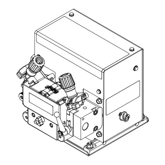
SECTION 9 – PARTS LIST Figure 9-1. Main Assembly OM-282692 Page 28... - Page 33 Main Assembly Item No. Dia. Mkgs. Part No. Description Quantity 276333 Bracket, Mtg Auto-Continuum Circuit Board 275200 Base, Auto-Continuum Drive 282890 Conn, Circ Aec 67 Pin Size 16S Rcpt Panel Mtg 228035 Valve, 34vdc 1way .750-14 Thd 2mm Orf 100 psi 276419 Wrapper, Auto-Continuum Feeder 283621...
- Page 34 Ref. 274772-G Figure 9-2. Drive Assembly Drive Assembly Item No. Dia. Mkgs. Part No. Description Quantity 275201 Block, Inlet Automation 276525 Screw, Thumb Stl ..250-20 x .375 Pld Nylon Head 275202 Assy, Power Pin Block Lh (includes) 275203 —Block, Power Pin Lh 073432 —Ftg, Hose Brs Barbed M 3/16 Tbg X 1/8 Npt 277263...
- Page 35 281081-A Figure 9-3. Wire Drive Assembly, No Motor Wire Drive Assembly, No Motor Item No. Dia. Mkgs. Part No. Description Quantity 260262 Assy, Pressure Arm Left 260263 Assy, Pressure Arm Right 259150 Spring, Double Torsion .408 OD .051 Wire 280878 Pin, Gear Idler 261793 Pin, Clevis .250 OD X 2.500 Lg W/Groove...
- Page 36 Figure 9-4. Adapter, Hercules Torch Item No. Dia. Mkgs. Part No. Description Quantity 284479 Enclosure, Optimax Torch Adapter 284630 Insulator, Adapter 284499 Adapter, Power Cable (Includes) 284501 —Bus Bar, 2.750 X 1.500 X .375 284503 —Adapter, Power Cable 284638 Bracket, Mtg Hercules Adapter B11N18 Coupler, Water, 5/8”-18 Lh 286747...
- Page 37 Notes...
- Page 38 Notes...
- Page 39 Effective January 1, 2023 (Equipment with a serial number preface of ND or newer) This limited warranty supersedes all previous Miller warranties and is exclusive with no other guarantees or war- ranties expressed or implied. � CoolBelt, PAPR Blower, and PAPR Face...
-
Page 40: Owner's Record
Appleton, WI 54914 USA tact your distributor and/or equipment manu- facturer’s Transportation Department. International Headquarters–USA USA Phone: 920-735-4505 USA & Canada FAX: 920-735-4134 International FAX: 920-735-4125 For International Locations Visit www.MillerWelds.com ORIGINAL INSTRUCTIONS – PRINTED IN USA © Miller Electric Mfg. LLC 2023-04...
Need help?
Do you have a question about the Hercules Drive and is the answer not in the manual?
Questions and answers