
Related Manuals for Emerson White-Rodgers P210


Summary of Contents for Emerson White-Rodgers P210
- Page 1 Single-Stage Thermostat with scheduling Install Guide Want to install the easy way? Model # P210 Made in China 37-7578...
- Page 2 GUIDE CONTENTS Preparations ..........3 Thermostat details ........4 Removal of your old thermostat....5 Mounting and wiring your new thermostat .. 10 Checking thermostat operation....12 Programming your thermostat ....16 Specifications ..........33 Troubleshooting .......... 35 WARNING Failure to follow and read all instructions carefully before installing or operating this control could cause personal injury and/or property damage.
-
Page 3: Check Package Contents
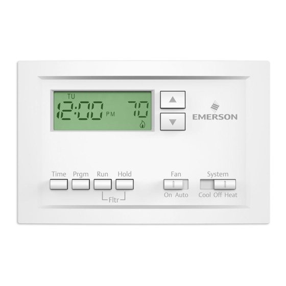
1. PREPARATIONS 1.1 Check package contents This package should contain the following items: • Thermostat • Mounting screws and wall anchors (x2) • 2 AAA batteries • Terminal wire label stickers • Installation instructions 1.2 Gather tools Required tools: □ Flat-head Screwdriver □ Small pliers (needle-nose) □ Drill with 3/16” (4 mm) bit Optional tools: □... - Page 4 2. THERMOSTAT DETAILS The thermostat buttons and switches Raises temperature setting. Lowers temperature setting. TIME button. PRGM (program) button. RUN (run program) button. HOLD temperature button. Time Prgm Hold System FAN switch (ON, AUTO). On Auto Cool Off Heat Fltr SYSTEM switch (COOL, OFF, HEAT).
-
Page 5: Removing Old Thermostat
3. REMOVING OLD THERMOSTAT 3.1 Turn off power WARNING To prevent electrical shock and/or equipment damage, disconnect electrical power to the system at the main fuse or circuit breaker box, or by flipping a switch at the air handler. Do not restore power until installation is complete. To ensure the power to your heating and cooling system has been turned off, try to turn on heating or cooling by changing the temperature on your old thermostat. - Page 6 3.2 Remove the old thermostat cover Remove the old thermostat’s front cover from the wall base. Some covers pull off easily, while others may need to be removed by prying the cover off with a screwdriver. CAUTION Your old thermostat may have a sealed glass tube containing mercury. Be careful not to damage the tube or dispose of the tube in your trash. For safe disposal information, please see Mercury Notice on page 43.
- Page 7 Terminal labeling reference chart If your current terminal has Label the wires with the Terminal function the following letter following letters RH, R, R5, 5 24V Power (Heating) 24V Power (Cooling) W, W1, 4 Heating Relay Y, Y1 Cooling Relay Fan Relay Reversing Valve (for heat pump applications energized in Cool mode)
- Page 8 If you have a heat pump with reversing valve, connect Y and W with a jumper wire on your new thermostat. If you need help with labeling and wiring, please contact Customer Support at 877.654.9394 or email wr.techsupport@emerson.com — we’re here to help!
- Page 9 3.5 Remove old thermostat base With all of your wires disconnected and properly labeled, you may now safely remove the thermostat base from your wall. Tip: Worried about having your wires falling into your wall? Keep the wires secure by wrapping the them around a pencil.
- Page 10 4. MOUNTING AND WIRING YOUR NEW THERMOSTAT 4.1 Install new thermostat base Mount your new thermostat base using the supplied screws. Drill holes and insert wall anchors to secure the thermostat base to the wall, if necessary.
- Page 11 4.2 Connect wires to corresponding terminal blocks Match each labeled wire to it’s corresponding terminal on the mounted thermostat base. Insert each labeled wire into the hole of it’s matching terminal, and using the screwdriver, tighten the screw on the terminal block securely. CAUTION Take care when securing and routing wires so they do not short to adjacent terminals or rear of thermostat.
-
Page 12: Check Thermostat Operation
5. CHECK THERMOSTAT OPERATION Tip: If at any time during testing your system does not operate properly, please contact Customer Support at 877.654.9394 or email wr.techsupport@emerson.com 5.1 Fan operation If your system does not have a G terminal connection, skip to 5.2 Heating system. -
Page 13: Heating System
5.2 Heating system 1. Move SYSTEM switch to HEAT position. If the heating system has a standing pilot, be sure to light it. 2. Press to adjust thermostat setting room temperature. The heating system should begin to operate. 3. Press to adjust temperature setting below room temperature. The heating system should stop operating. 5.3 Cooling system CAUTION To prevent compressor and/or property damage, if the outdoor temperature is below 50°, DO NOT operate the cooling system... - Page 14 5.4 Typical wiring diagrams THERMOSTAT C ‡ SYSTEM THERMOSTAT JUMPER C ‡ WIRE Cooling Heating SYSTEM THERMOSTAT 24 VAC JUMPER 120 VAC C ‡ System Relay System WIRE SYSTEM Neutral Cooling Heating THERMOSTAT 24 VAC 120 VAC C ‡ System Relay System HEATING...
- Page 15 Reversing Compressor Cooling 24 VAC 120 VAC 24 VAC 120 VAC Valve* Contactor Relay System Relay Neutral * Reversing valve is energized when the Neutral system switch is in the COOL position 24 VAC TRANSFORMER 120 VAC TRANSFORMER 24 VAC 120 VAC Neutral * Reversing valve is energized when the...
- Page 16 6. PROGRAMMING YOUR THERMOSTAT Before you begin programming your thermostat, you should be familiar with its features and with the display and the location and operation of the thermostat buttons. Your thermostat consists of two parts: the thermostat cover and the base.
- Page 17 Time Prgm Hold System On Auto Cool Off Heat Fltr...
-
Page 18: The Display
6.2 The display Indicates day of the week. Flame icon () is displayed when the SYSTEM switch is in the HEAT position. Snowflake icon ()is displayed (non-flashing) when the SYSTEM switch is in the COOL position. Snowflake is displayed (flashing) if the thermostat is in lockout mode to prevent the compressor from cycling too quickly. - Page 19 MO TU WE TH FR SA SU FLTR HOLDCHANGE...
-
Page 20: Configuration Menu
6.3 Configuration menu The configuration menu allows you to set certain thermostat operating characteristics to your system or personal requirements. Press RUN to make sure the thermostat is in the run program mode, then press PRGM and RUN at the same time to enter the configuration menu. - Page 21 3. After releasing the button, “HOLD” on the display will blink. 4. Use or to set the temperature to your preference. The thermostat will maintain this temperature setting for 3 hours with “HOLD” blinking to remind you it is in Temporary Hold. After 3 hours the thermostat will go back to the program temperature and “HOLD”...
- Page 22 5. Select filter replacement run time – The thermostat will display “FLTR” after a set time of operation. This is a reminder to change or clean your air filter. This time can be set from 0 to 1950 hours in 50 hour increments. A selection of 000 will cancel this feature.
- Page 23 Configuration Menu Step Press Button(s) Displayed (Factory Default) Press to select: COMMENTS HOLD 0 to 8 hrs (in Select temporary Hold time PRGM (0:00) 15 minute increments) and RUN Select FA or SL (Fast or Slow) heating cycle rate HOLD* (FA) HOLD* Select display backlight OFF or ON...
- Page 24 6.4 Operating features This section contains information about the many features of your new thermostat. • SIMULTANEOUS HEATING/COOLING PROGRAM STORAGE — When programming, you can enter both your heating and cooling programs at the same time. There is no need to reprogram the thermostat at the beginning of each season.
-
Page 25: Planning Your Program
6.5 Programming your thermostat This section will help you plan your thermostat’s program to meet your needs. For maximum comfort and efficiency, keep the following guidelines in mind when planning your program: • When heating (cooling) your building, program the temperatures to be cooler (warmer) when the building is vacant or during periods of low activity. - Page 26 room temperature alternately. SAMPLE Heating/Cooling Schedule Plan (Factory Program) SATURDAY (1 DAY) SUNDAY (1 DAY) WEEKDAY (5 DAY) Start Start Start Period Time Temperature Time Temperature Time Temperature 6:00 AM 70°F 6:00 AM 70°F 6:00 AM 70°F 8:00 AM 62°F 8:00 AM 62°F 8:00 AM...
- Page 27 Use the following table to plan your program time periods and the temperatures you want during each period. Fill in the complete table to have a record of your programs. Heating/Cooling Schedule Plan SATURDAY (1 DAY) SUNDAY (1 DAY) WEEKDAY (5 DAY) Start Start Start...
-
Page 28: Entering Your Program
Entering your program Follow these steps to enter the heating and cooling programs you have selected. Set Current Time and Day 1. Press TIME button once. The display will show the hour only. EXAMPLE: 2. Press and hold either or until you reach the correct hour and AM/PM designation (AM begins at midnight;... - Page 29 4. Press and hold either or until you reach the correct minutes. 5. Press TIME once. The display will show the day of the week. 6. Press or until you reach the current day of the week. 7.
- Page 30 3. Press or to change the displayed temperature to your selected temperature for the 1st heating program period. 4. Press TIME once (the programmed time will flash). Press or until your desired time appears. The time will change in 15 minute increments.
- Page 31 12. When you have completed entering your heating program, press RUN. Set Cooling Program CAUTION If the outside temperature is below 50° F, disconnect power to the cooling system before programming. Energizing the air conditioner compressor during cold weather may cause personal injury or property damage. 1.
- Page 32 Check your programming Follow these steps to check your thermostat programming one final time before beginning thermostat operation. 1. Move SYSTEM switch to HEAT position. 2. Press PRGM to view the 1st weekday heating period time and temperature. Each time you press PRGM, the next heating period time and temperature will be displayed in sequence for weekday, then weekend program periods (you may change any time or temperature during this procedure).
-
Page 33: Specifications
7. SPECIFICATIONS ELECTRICAL DATA Electrical Rating: 8 to 30 VAC 50/60 Hz. or D.C. 0.05 to 1.0 Amps (Load per terminal) 1.5 Amps Maximum Total Load (All terminals combined) THERMAL DATA Setpoint Temperature Range: 45°F to 90°F (7°C to 32°C) Operating Ambient Temperature Range: 32°F to 105°F Operating Humidity Range: 0 to 90% RH (non-condensing) Shipping Temperature Range: -4°F to 149°F... - Page 34 APPLICATIONS For use with: • Standard heat/cool or heat only systems • Electric heat systems • Gas or oil fired systems • Gas systems with intermittent ignition devices (I.I.D.) and/or vent dampers • Hydronic (hot water or steam) systems • Single-stage heat pump systems (no auxiliary heat) •...
- Page 35 8. TROUBLESHOOTING Reset Operation If a voltage spike or static discharge blanks out the display or causes erratic thermostat operation you can reset the thermostat by pressing , , and TIME at the same time. This also resets the factory defaults to the configura- tion menu and program.
- Page 36 Symptom Possible Cause Corrective Action No Heat/No Cool/No Fan 1. Blown fuse or tripped circuit breaker. Replace fuse or reset breaker. (common problems) 2. Furnace power switch to OFF. Turn switch to ON. 3. Furnace blower compartment door or Replace door panel in proper position to panel loose or not properly installed.
- Page 37 Symptom Possible Cause Corrective Action No Heat 1. Pilot light not lit. Re-light pilot. 2. SYSTEM Switch not set to HEAT. Set SYSTEM Switch to HEAT and raise setpoint temperature above room temperature. 3. Loose connection to thermostat or system. Verify thermostat and system wires are securely attached.
- Page 38 Symptom Possible Cause Corrective Action Heat, Cool or Fan Runs Constantly. 1. FAN Switch set to Fan ON. Check each wire connection to verify they are not shorted or touching 2. Possible short in wiring. together. No bare wire should stick 3.
- Page 39 Symptom Possible Cause Corrective Action Cooling Cycles Too Fast or Too Slow 1. The location of the thermostat and/or The cycle rate for cooling is fixed and the size of the Cooling System may can not be adjusted. Contact a local (narrow or wide temperature swing) be influencing the cycle rate.
- Page 40 Symptom Possible Cause Corrective Action Thermostat Does Not Follow Program 1. AM or PM set incorrectly in program. Check current clock and program settings including the AM or PM desig- 2. AM or PM set incorrectly on the clock. nations for each time period. If a voltage 3.
- Page 41 CONTACT US Customer support: 877.654.9394 or wr.techsupport@emerson.com...
- Page 43 MERCURY NOTICE This product does not contain mercury. However, this product may replace a product that contains mercury. Mercury and products containing mercury must not be discarded in household trash. Refer to thermostat-recycle.org for location to send product containing mercury. FOR CALIFORNIA RESIDENTS Warning: This product contains a chemical known to the state of California to cause cancer and birth defects and other reproductive harm.
Need help?
Do you have a question about the White-Rodgers P210 and is the answer not in the manual?
Questions and answers