Table of Contents
Advertisement
Quick Links
Safe Operation Practices • Set-Up • Operation • Maintenance • Service • Troubleshooting • Warranty
O
'
M
peratOr
s
anual
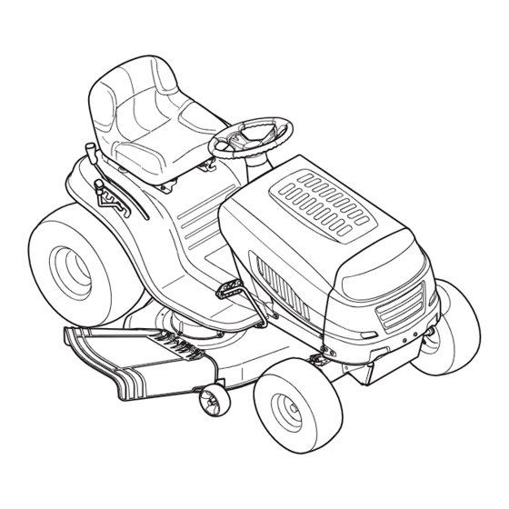
Model Series 780 Lawn Tractor
WARNING
READ AND FOLLOW ALL SAFETY RULES AND INSTRUCTIONS IN THIS MANUAL
BEFORE ATTEMPTING TO OPERATE THIS MACHINE.
FAILURE TO COMPLY WITH THESE INSTRUCTIONS MAY RESULT IN PERSONAL INJURY.
MTD LLC, P.O. BOX 361131 CLEVELAND, OHIO 44136-0019
Printed In USA
Form No. 769-09588
(December 6, 2013)
Advertisement
Table of Contents

Related Manuals for MTD 780 Series


Summary of Contents for MTD 780 Series
- Page 1 READ AND FOLLOW ALL SAFETY RULES AND INSTRUCTIONS IN THIS MANUAL BEFORE ATTEMPTING TO OPERATE THIS MACHINE. FAILURE TO COMPLY WITH THESE INSTRUCTIONS MAY RESULT IN PERSONAL INJURY. MTD LLC, P.O. BOX 361131 CLEVELAND, OHIO 44136-0019 Printed In USA Form No. 769-09588...
-
Page 2: Table Of Contents
Visit us on the web at www.mtdproducts.com ◊ Call a Customer Support Representative at (800) 800-7310 or (330) 220-4683 See How-to Maintenance and Parts Installation Videos at www.mtdparts.com/KnowledgeCenter ◊ Write us at MTD LLC • P.O. Box 361131 • Cleveland, OH • 44136-0019... -
Page 3: Safe Operation Practices
Important Safe Operation Practices WARNING! This symbol points out important safety instructions which, if not followed, could endanger the personal safety and/or property of yourself and others. Read and follow all instructions in this manual before attempting to operate this machine. Failure to comply with these instructions may result in personal injury. - Page 4 Slope Operation A missing or damaged discharge cover can cause blade contact or thrown object injuries. Slopes are a major factor related to loss of control and tip-over Stop the blade(s) when crossing gravel drives, walks, or accidents which can result in severe injury or death. All slopes roads and while not cutting grass.
- Page 5 Service Children Tragic accidents can occur if the operator is not alert to the Safe Handling of Gasoline: presence of children. Children are often attracted to the machine and the mowing activity. They do not understand To avoid personal injury or property damage use extreme the dangers.
-
Page 6: Spark Arrestor
Tampering with the governor setting can lead to a runaway do not stop within the this time frame, your machine engine and cause it to operate at unsafe speeds. Never tamper should be serviced professionally by an authorized MTD with factory setting of engine governor. Service Dealer. -
Page 7: Safety Symbols
Safety Symbols This page depicts and describes safety symbols that may appear on this product. Read, understand, and follow all instructions on the machine before attempting to assemble and operate. Symbol Description READ THE OPERATOR’S MANUAL(S) Read, understand, and follow all instructions in the manual(s) before attempting to assemble and operate DANGER—... - Page 8 2 — i ection mportant peration racticeS...
-
Page 9: Assembly & Set-Up
Shipping Brace Removal to all models. MTD reserves the right to change product specifications, designs and equipment without notice and WARNING! Make sure the riding mower’s engine is without incurring obligation. - Page 10 Attaching The Steering Wheel If the steering wheel for your tractor did not come attached, the hardware for attaching it has been packed within the steering wheel, beneath the steering wheel cap. Carefully pry off the steering wheel cap and remove the hardware. With the wheels of the tractor pointing straight forward, place the steering wheel over the steering shaft.
- Page 11 Gas and Oil Fill-up Setting the Deck Gauge Wheels (If Equipped) The gasoline tank is located under the hood. Do not overfill. Move the tractor on a firm and level surface, preferably pavement, and proceed as follows WARNING! Use extreme care when handling Select the height position of the cutting deck by placing gasoline.
-
Page 12: Controls & Features
Controls & Features Ignition Switch Throttle/Choke Lever Brake Pedal Parking Brake Lever Drive Pedal Shift Lever Deck Lift Lever Cup Holder PTO (Blade Engage) Lever NOTE: Steering wheel not shown for clarity Figure 4-1 Lawn Tractor controls and features are illustrated in and described on the following pages. WARNING! Read and follow all safety rules and instructions in this manual, including the entire Operation section, before attempting to operate this machine. -
Page 13: Shift Lever
Throttle / Choke Control Shift Lever The throttle control lever is located on the left side The shift lever is located on the left side of the fender and has of the tractor’s dash panel. This lever controls the three positions, FORWARD, NEUTRAL and REVERSE. The tractor must not be in motion when the moving shift lever. - Page 14 Drive Pedal Deck Lift Lever The drive pedal is located on the right side of the Found on your tractor’s right fender, the deck lift tractor, along the running board. Depress the lever is used to change the height of the cutting drive pedal forward and the tractor will move in deck.
-
Page 15: Operation
Operation Engaging the Parking Brake To engage the parking brake: Fully depress the brake pedal and hold it down with your foot. Move the parking brake lever down into the parking brake position. Release the brake pedal to allow the parking brake to engage. -
Page 16: Stopping The Engine
Stopping the Engine Driving On Slopes WARNING! Refer to the SLOPE GAUGE in the Important Safe Operation If you strike a foreign object, stop the Practices section in the front of this manual to help determine engine, disconnect the spark plug wire(s) and slopes where you may operate the tractor safely. - Page 17 Using the Deck Lift Lever Headlights To raise the cutting deck, move the deck lift lever to the left, then • The Headlights are ON whenever the tractor’s engine is place it in the notch best suited for your application. Refer to running.
-
Page 18: Maintenance & Adjustment
Maintenance & Adjustments Maintenance Reinstall the oil drain plug securely. Be careful not to overtighten. WARNING: Before performing any maintenance or Refill the engine with new motor oil as instructed in the repairs, disengage PTO, move shift lever into neutral Engine Owner’s Manual packed with your unit. - Page 19 Deck Wash System™ Charging A hex bolt and washer can be found on your tractor’s deck surface. IMPORTANT: When charging your tractor’s battery, use only a See Figure 6-2. charger designed for 12V lead-acid batteries. Read your battery charger’s Owner’s Manual prior to charging your tractor’s battery. Always follow its instructions and heed its warnings.
-
Page 20: Seat Adjustment
If the tractor does not come to a complete stop when the brake pedal is completely depressed, or if the tractor’s rear wheels can roll with the parking brake applied, the brake is in need of adjustment. See an authorized MTD Service Dealer to have your brakes properly adjusted. 6— M &... -
Page 21: Maintenance Schedule
Maintenance Schedule Before Every Every Every Every Prior Each use 10 Hours 25 Hours 50 Hours 100 Hours to Storing Clean Hood/Dash Louvers Check Engine Oil Level Check Air Filter for Dirty, Loose or Damaged Parts Clean and Re-oil Air Filter’s Foam Precleaner Replace Air Filter Element Change Engine Oil and Replace Oil Filter Clean Battery Terminals... -
Page 22: Service
Service Cutting Deck Removal 42” Deck To remove the cutting deck, proceed as follows: Place the PTO (Blade Engage) lever in the disengaged (OFF) position and engage the parking brake. Lower the deck by moving the deck lift lever into the bottom notch on the right fender. -
Page 23: Cutting Blades
Carefully remove the PTO cable from the rear of the cutting Connect positive (+) cable to positive post (+) of your deck by removing the bow-tie clip which secures it. Remove tractor’s discharged battery. the spring from the deck idler bracket. See Figure 7-4. Connect the other end of the cable to the (positive +) post of the jumper battery. - Page 24 The blades may be removed as follows. WARNING! A poorly balanced blade will cause Remove the deck from beneath the tractor, (refer to Cutting excessive vibration, may cause damage to the Deck Removal earlier in this section) then gently flip the deck tractor and/or result in personal injury.
-
Page 25: Dealer
Carefully remove the deck belt from around the two Pull the right side of the belt, and place the narrow V side of spindle pulleys and the two deck idler pulleys. See Figure the belt into the PTO pulley. 7-7. While holding the belt and pulley together, rotate the To place the new belt, begin by routing the belt around the pulley to the left. -
Page 26: Troubleshooting
Troubleshooting Problem Cause Remedy Engine fails to start 1. PTO/Blade engaged. 1. Place PTO lever the in disengaged (OFF) position. 2. Spark plug wire disconnected. 2. Connect wire to spark plug. 3. Fuel tank empty, or stale fuel. 3. Fill tank with clean, (less than 30 days old) gas. 4. -
Page 27: Replacement Parts
NOTE: This Operators Manual covers a range of product specifications for various models. Characteristics and features discussed and/ or illustrated in this manual may not be applicable to all models. MTD reserves the right to change product specifications, designs and equipment without notice and without incurring obligation. -
Page 28: Attachments & Accessories
Attachments & Accessories The following attachments and accessories are compatible for these models of Lawn Tractors. See the retailer from which you purchased your tractor, an authorized MTD Service Dealer or phone (800) 800-7310 for information regarding price and availability. CAUTION: These models of Lawn Tractors are NOT designed for use with any type of ground-engaging attachments (e.g. - Page 29 Notes...
-
Page 30: Emission Control Statement
Any warranted part that is not scheduled for replacement as required maintenance in the written instructions supplied is warranted for the warranty period stated above. If the part fails during the period of warranty coverage, the part will be repaired or replaced by MTD Consumer Group Inc according to subsection (4) below. - Page 31 The repair or replacement of any warranted part otherwise eligible for warranty coverage may be excluded from such warranty coverage if MTD Consumer Group Inc demonstrates that the outdoor equipment has been abused, neglected, or improperly maintained, and that such abuse, neglect, or improper maintenance was the direct cause of the need for repair or replacement of the part. That notwithstanding, any adjustment of a component that has a factory installed, and properly operating, adjustment limiting device is still eligible for warranty coverage.
-
Page 32: Warranty
MANUFACTURER’S LIMITED WARRANTY FOR The limited warranty set forth below is given by MTD LLC with Log splitter pumps, valves, and cylinders have a separate respect to new merchandise purchased and used in the United one- year warranty. States and/or its territories and possessions, and by MTD Products...
Need help?
Do you have a question about the 780 Series and is the answer not in the manual?
Questions and answers