Table of Contents
Advertisement
Quick Links
Safe Operation Practices • Set-Up • Operation • Maintenance • Service • Troubleshooting • Warranty
O
'
M
peratOr
s
anual
Hydrostatic Lawn Tractor — Model Series 790
Hydrostatic Lawn Tractor — Model Series 790
WARNING
READ AND FOLLOW ALL SAFETY RULES AND INSTRUCTIONS IN THIS MANUAL
BEFORE ATTEMPTING TO OPERATE THIS MACHINE.
FAILURE TO COMPLY WITH THESE INSTRUCTIONS MAY RESULT IN PERSONAL INJURY.
MTD LLC, P.O. BOX 361131 CLEVELAND, OHIO 44136-0019
Printed In USA
Form No. 769-10155A
(March 9, 2015)
Advertisement
Table of Contents

Subscribe to Our Youtube Channel
Related Manuals for MTD Series 790


Summary of Contents for MTD Series 790
- Page 1 Safe Operation Practices • Set-Up • Operation • Maintenance • Service • Troubleshooting • Warranty ’ peratOr anual Hydrostatic Lawn Tractor — Model Series 790 Hydrostatic Lawn Tractor — Model Series 790 WARNING READ AND FOLLOW ALL SAFETY RULES AND INSTRUCTIONS IN THIS MANUAL BEFORE ATTEMPTING TO OPERATE THIS MACHINE.
-
Page 2: Table Of Contents
Visit us on the web at www.mtdproducts.com See How-to Maintenance and Parts Installation Videos at www.mtdparts.com/KnowledgeCenter ◊ Call a Customer Support Representative at (800) 800-7310 or (330) 220-4683 ◊ Write us at MTD LLC • P.O. Box 361131 • Cleveland, OH • 44136-0019... -
Page 3: Safe Operation Practices
Important Safe Operation Practices WARNING! This symbol points out important safety instructions which, if not followed, could endanger the personal safety and/or property of yourself and others. Read and follow all instructions in this manual before attempting to operate this machine. Failure to comply with these instructions may result in personal injury. - Page 4 Slope Operation A missing or damaged discharge cover can cause blade contact or thrown object injuries. Slopes are a major factor related to loss of control and tip-over Stop the blade(s) when crossing gravel drives, walks, or accidents which can result in severe injury or death. All slopes roads and while not cutting grass.
- Page 5 Service Children Tragic accidents can occur if the operator is not alert to the Safe Handling of Gasoline: presence of children. Children are often attracted to the machine and the mowing activity. They do not understand To avoid personal injury or property damage use extreme the dangers.
-
Page 6: Spark Arrestor
Tampering with the governor setting can lead to a runaway do not stop within the this time frame, your machine engine and cause it to operate at unsafe speeds. Never tamper should be serviced professionally by an authorized MTD with factory setting of engine governor. Service Dealer. -
Page 7: Safety Symbols
Safety Symbols This page depicts and describes safety symbols that may appear on this product. Read, understand, and follow all instructions on the machine before attempting to assemble and operate. Symbol Description READ THE OPERATOR’S MANUAL(S) Read, understand, and follow all instructions in the manual(s) before attempting to assemble and operate DANGER —... - Page 8 2 — i ection mportant peration racticeS...
-
Page 9: Assembly & Set-Up
Characteristics and features Lower Deck Discharge Chute Deflector discussed and/or illustrated in this manual may not be applicable to all models. MTD LLC reserves the right to change product WARNING! Never operate the mower deck specifications, designs and equipment without notice and without the chute deflector installed and in the without incurring obligation. - Page 10 Attaching The Steering Wheel If the steering wheel for your tractor did not come attached, the hardware for attaching it has been packed within the steering wheel, beneath the steering wheel cap. Carefully pry off the steering wheel cap and remove the hardware. With the wheels of the tractor pointing straight forward, place the steering wheel over the steering shaft.
- Page 11 Tire Pressure Setting the Deck Gauge Wheels (if so equipped) Move the tractor on a firm and level surface, preferably WARNING! Maximum tire pressure under any pavement, and proceed as follows: circumstances is 30 psi. Equal tire pressure should be maintained at all times.
-
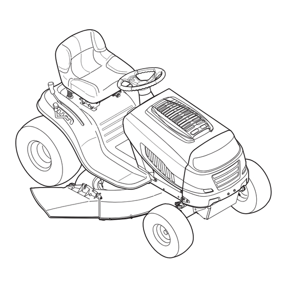
Page 12: Controls & Features
Controls and Features Parking Brake Lever Throttle/Choke Lever Parking Brake Pedal Ignition Switch Module Speed Control Lever Deck Lift Lever PTO (Blade Engage) Lever Figure 4-1 Lawn Tractor controls and features are illustrated in Figure 4-1 and described on the following pages. WARNING! Read and follow all safety rules and instructions in this manual, including the entire Operation section, before attempting to operate this machine. -
Page 13: Throttle Control Lever
Throttle Control Lever On/Lights The throttle control lever is located on the left side Start of the tractor’s dash panel. This lever controls the speed of the engine and when pushed all the way forward, the choke control also. When set in a given position, the throttle will maintain a uniform engine speed. - Page 14 Speed Control Lever In an sudden situation, fully depress the brake pedal to bring the tractor to a stop and then immediately move the speed control The speed control lever, located on the left rear fender, controls lever to the “N” neutral position the ground speed of the lawn tractor as well as the direction of IMPORTANT: Do not use the parking brake pedal to control...
-
Page 15: Operation
The red indicator light at the top, left corner of the key malfunction, do not operate the tractor. Contact an authorized switch module will be ON while activated. See . MTD service dealer. Reverse • The safety interlock system prevents the engine from... -
Page 16: Stopping The Engine
Once activated (indicator light ON), the tractor can be Engage the tractor’s parking brake. driven in reverse with the cutting blades (PTO) engaged. Activate the choke control. Always look down and behind before and while backing to Turn the ignition key clockwise to the START position. After make sure no children are around. -
Page 17: Engaging The Blades
IMPORTANT: First-time operators should use slower Keep the throttle lever in the FAST (rabbit) position for the speeds. Become completely familiar with the tractor’s most efficient use of the cutting deck or other (separately operation and controls before operating the tractor in at available) attachments. - Page 18 Mulching (if so equipped) Moving The Tractor Manually Select models come equipped with a mulch kit which Your tractor’s transmission is equipped with a hydrostatic relief incorporates special blades, already standard on the tractor, in a valve for occasions when it is necessary to move the tractor process of recirculating grass clippings repeatedly beneath the manually.
-
Page 19: Maintenance & Adjustment
Maintenance & Adjustments Maintenance Service oil filter (if so equipped) as instructed in the separate Engine Operator/Owner Manual packed with your unit. WARNING! Before performing any maintenance or Perform the above steps in the opposite order after oil has repairs, disengage PTO, move shift lever into neutral finished draining. - Page 20 Push the oil drain hose (packed with this manual) onto the • Always keep the rubber boot positioned over the positive oil drain port. Route the opposite end of the hose into an terminal to prevent shorting. appropriate oil collection container with at least a 2.5 quart IMPORTANT: If removing the battery for any reason, capacity, to collect the used oil.
- Page 21 Battery Failures Drive the tractor to a level, clear spot on your lawn, near enough for your garden hose to reach. Some common causes for battery failure are: CAUTION: Make certain the tractor’s discharge • Incorrect initial activation chute is directed AWAY from your house, garage, •...
-
Page 22: Seat Adjustment
If the tractor does not come to a complete stop when the brake pedal is completely depressed, or if the tractor’s rear wheels can roll with the parking brake applied, the brake is in need of adjustment. See an authorized MTD Service Dealer to have your brakes properly adjusted. 6— M &... -
Page 23: Maintenance Schedule
NOTE: This Operators Manual covers a range of product specifications for various models. Characteristics and features discussed and/ or illustrated in this manual may not be applicable to all models. MTD reserves the right to change product specifications, designs and equipment without notice and without incurring obligation. -
Page 24: Service
Service Cutting Deck Removal NOTE: Models equipped with a 38-inch deck have one deck idler pulley. Models equipped with a 42- and 46-inch deck have two deck idler pulleys. To remove the cutting deck, proceed as follows: Place the PTO (Blade Engage) lever in the disengaged (OFF) position and engage the parking brake. - Page 25 Jump Starting WARNING! Never jump start a damaged or frozen battery. Be certain the vehicles do not touch, and ignitions are off. Do not allow cable clamps to touch. Connect positive (+) cable to positive post (+) of your tractor’s discharged battery. Connect the other end of the cable to the (positive +) post of the jumper battery.
-
Page 26: Cutting Blades
Cutting Blades WARNING! Shut the engine off and remove ignition key before removing the cutting blade(s) for sharpening or replacement. Protect your hands by using heavy gloves when grasping the blade. WARNING! Periodically inspect the blade and/or spindle for cracks or damage, especially after you’ve struck a foreign object. -
Page 27: Dealer
NOTE: Several components must be removed and special tools (i.e. air/impact wrench) in order to change the tractor’s drive belt. See an authorized MTD Service Dealer to have your drive belt replaced or phone Customer Support as instructed on page 2 for information on ordering a Service Manual. -
Page 28: Troubleshooting
Troubleshooting Problem Cause Remedy Engine fails to start 1. PTO/Blade engaged. 1. Place knob (or lever) in disengaged (OFF) position. 2. Spark plug wire disconnected. 2. Connect wire to spark plug. 3. Fuel tank empty, or stale fuel. 3. Fill tank with clean, fresh (less than 30 days old) gas. -
Page 29: Replacement Parts
NOTE: This Operators Manual covers a range of product specifications for various models. Characteristics and features discussed and/ or illustrated in this manual may not be applicable to all models. MTD reserves the right to change product specifications, designs and equipment without notice and without incurring obligation. -
Page 30: Attachments & Accessories
Attachments & Accessories The following attachments and accessories are compatible for Model Series 700 Hydrostatic Lawn Tractors. See the retailer from which you purchased your tractor, an authorized MTD Service Dealer or phone (800) 800-7310 for information regarding price and availability. CAUTION:... - Page 31 Any warranted part that is not scheduled for replacement as required maintenance in the written instructions supplied is warranted for the warranty period stated above. If the part fails during the period of warranty coverage, the part will be repaired or replaced by MTD Consumer Group Inc according to subsection (4) below.
- Page 32 The repair or replacement of any warranted part otherwise eligible for warranty coverage may be excluded from such warranty coverage if MTD Consumer Group Inc demonstrates that the outdoor equipment has been abused, neglected, or improperly maintained, and that such abuse, neglect, or improper maintenance was the direct cause of the need for repair or replacement of the part. That notwithstanding, any adjustment of a component that has a factory installed, and properly operating, adjustment limiting device is still eligible for warranty coverage.
- Page 33 Notes...
-
Page 34: Emission Control Statement
11— n ection oteS... - Page 35 11 — n ection oteS...
-
Page 36: Warranty
MANUFACTURER’S LIMITED WARRANTY FOR The limited warranty set forth below is given by MTD LLC with Log splitter pumps, valves, and cylinders have a separate respect to new merchandise purchased and used in the United one- year warranty. States and/or its territories and possessions, and by MTD Products...
Need help?
Do you have a question about the Series 790 and is the answer not in the manual?
Questions and answers