Table of Contents

Related Manuals for MTD Series 790


Summary of Contents for MTD Series 790
- Page 1 Safe Operation Practices • Set-Up • Operation • Maintenance • Service • Troubleshooting • Warranty Hydrostatic Lawn Tractor m Model Series 790 MTD LLC, P.O. BOX 361131 CLEVELAND, OHiO 44136-0019 PrintedIn USA FormNo.769-05520A (March29,2010)
-
Page 2: Customer Support
Choose from the options below: Visit us on the web at www.mtdproducts.com Call a Customer Support Representative at (800) 800-7310 or (330) 220-4683 Write us at MTD LLC • RO. Box 361131 • Cleveland, OH • 44136-0019... -
Page 3: Important Safe Operation Practices
ImportantSafeOperation Practices WARNING! This symbol points out important safety instructions which, if not followed, could endanger the personal safety and/or property of yourself and others. Read and follow all instructions in this manual before attempting to operate this machine. Failure to comply with these instructions may result in personal injury. - Page 4 12. Amissing ordamaged discharge cover can cause blade Slope Operation contact orthrown o bject injuries. Slopes are a major factor related to loss of control and tip-over 13. Stop t heblade(s) when crossing gravel drives, walks, or accidents which can result in severe injury or death. All slopes roads a nd while notcutting g rass.
-
Page 5: Safe Handling Of Gasoline
Children Service Tragic accidents ca n occur if the operator is not alert to the SafeHandling of Gasoline: presence of children. Children are often attracted to the machine and the mowing activity. They do not understand To avoid personal injury or property damage use extreme the dangers. -
Page 6: Spark Arrestor
Periodically check to make sure the blades come to Donot modify engine complete stop within approximately (5) five seconds after To avoid serious injury or death, do not modify engine in any operating the blade disengagement control. If the blades way. -
Page 7: Safety Symbols
SafetySymbols This page depicts and describes safety symbols that may appear on this product. Read, understand, and follow all instructions on the machine before attempting to assemble and operate. READ THE OPERATOR'S MANUAL(S) Read, understand, and follow all instructions in the manual(s) before attempting assemble and operate DANGER--... - Page 8 or a corner of a building... or a fence post ' FOldo,_ " .- 22 diine a 15Oslope "o 15 ° Usethis page as a guide to determine slopeswhere you may not operate safely. WARNING! Do not operate your lawn mower on such slopes. Do not mow on inclines with a slope in excess of 15 degrees (a rise of approximately 2-1/2 feet every 10 feet).
-
Page 9: Assembly And Setup
Characteristics and features the tractor. discussed and/or illustrated in this manual may not be applicable Shipping BraceRemoval to all models. MTD LLC reserves the right to change product specifications, designs and equipment without notice and without incurring obligation. -
Page 10: Attaching The Steering Wheel
Attaching The Steering Wheel Attaching The Seat If the steering wheel for your tractor did not come attached, If the seat for your tractor was not attached at the factory, refer hardware for attaching it has been packed within the steering to the following steps. -
Page 11: Tire Pressure
TirePressu re Gasand Oil Fill-up The gasoline tank is located under the hood. Do not overfill. circumstances is 30 psi. Equal tire pressure should maintained ARNING! at all times. Never exceed the maximum Maximum tire pressure under any gasoline. Gasoline is extremely flammable and the inflation... -
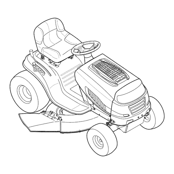
Page 12: Controls And Features
Controls a nd Features Parking Brake Lever Parking Brake Pedal Throttle/Choke Lever ignition Switch Module Speed Control Lever PTO (Blade Engage) Lever Deck Lift Lever Figure 4=1 Lawn Tractor controls and features are illustrated in Fig 4-1 and described on the following pages. -
Page 13: Ignition Switch
ThrottleControlLever On/Lights The throttle control lever is located on the right side of the tractor's dash panel. This lever controls the speed of the engine and when pushed all the way forward, the choke control also. When set in a given position, the throttle will maintain a uniform... -
Page 14: Speed Control Lever
unattended. Always disengage PTO, move speed ARNING! Never leave a running machine control lever into neutral position, set parking brake, stop engine and remove key to prevent unintended starting. IMPORTANT: Prior to operating the tractor, refer to both Safety Interlock Switches and Starting The Engine in the Operation SPEED section... -
Page 15: Operation
Contact an authorized switch module will be ON while activated. See Fig. 5-1. MTD service dealer. The safety interlock system prevents the engine from cranking or starting... - Page 16 Once activated (indicator light ON), the tractor can be Engage the tractor's parking brake. driven in reverse with the cutting blades (PTO) engaged. Activate the choke control. Always look down and behind before and while backing to Turn the ignition key clockwise to the START position.
-
Page 17: Usingthe Decklift Lever
iMPORTANT: First-time operators should use slower Keep the throttle lever in the FAST (rabbit) position for the speeds. Become completely familiar with the tractor's most efficient use of the cutting deck or other (separately available) attachments. operation and controls before operating the tractor in at higher... - Page 18 Mulching MovingTheTractorManually Select models come equipped with a mulch kit which Your tractor's transmission is equipped with a hydrostatic relief incorporates special blades, already standard on the tractor, in a valve for occasions when it is necessary to move the tractor process of recirculating grass clippings repeatedly...
-
Page 19: Maintenance And Adjustments
Maintenance& Adjustments Maintenance Perform the above steps in the opposite order after oil has finished draining. WARNING! Before performing any maintenance Refill the engine with new motor oil as instructed in the repairs, disengage PTO, move shift lever into neutral Engine Operator/Owner Manual packed with your machine. - Page 20 Pinch the tabs on the oil drain valve, then pull outward to If removing the battery for any reason, IMPORTANT: begin draining oil. SeeFig 6-2. disconnect the NEGATIVE(Black) wire from it's terminal first, followed by the POSITIVE(Red) wire. When re-installing the After the oil has finished draining, push the end of the oil battery, always connect the POSITIVE(Red) wire its terminal drain valve back in, until the tabs click into place.
-
Page 21: Cleaningthe Engineanddeck
Freezing Disengage the PTO (Blade Engage), set the parking brake and stop the engine. Undercharging Thread the hose coupler (packagedwithyourtractor's Corroded connections Operator's Manual) onto the end of your garden hose. These failures are NOT covered by your tractor's warranty. Attach the hose coupler to the water port on the deck's surface. -
Page 22: Seat Adjustment
See an authorized MTD Service Dealer to have your brakes properly adjusted Figure 6-5 Sideto Side If the cutting deck appears to be mowing... -
Page 23: Maintenance Schedule
Characteristics and features discussed and/ or illustrated in this manual may not be applicable to all models. MTD LLC reserves the right to change product specifications, designs and equipment without notice and without incurring obligation. IMPORTANT:... -
Page 24: Cutting Deck Removal
Service Cutting Deck Removal 42" Deck NOTE: Models equipped with a 38-inch deck have one deck idler pulley. Models equipped with a 42- and 46-inch deck have two deck idler pulleys. To remove the cutting deck, proceed as follows: Place the PTO (Blade Engage) lever in the disengaged (OFF) position and engage... - Page 25 Carefully remove the PTO cable from the rear of the Jump Starting cutting deck by removing the hair pin clip which secures it. Remove the spring from the deck idler bracket. See Fig. 7-4 on the next page. battery. Be certain the vehicles do not touch, and ARNING! Never jump start a damaged...
-
Page 26: Changing The Deckbelt
Cutting 8lades WARNING! Shut the engine off and remove ignition key before removing the cutting blade(s) for sharpening or replacement. Protect your hands by using heavy gloves when grasping the blade. WARNING! Periodically inspect the blade and/or spindle for cracks or damage, especially after you've struck a foreign... - Page 27 (i.e. air/impact wrench) in order to change the tractor's drive belt. See an authorized MTD Service Dealer to have your drive belt replaced or phone Customer Support as instructed on page 2 for information on ordering a Service Manual.
-
Page 28: Troubleshooting
Troubleshooting Problem Cause Remedy Engine fails to start PTO/Blade engaged. 1. Place knob (or lever) in disengaged (OFF) position. 2. Spark plug wire disconnected. 2. Connect wire to spark plug. 3. Fuel tankempty, or stale fuel. 3. Fill tank with clean, fresh (less than 30 days old) gas. -
Page 29: Replacement Parts
Characteristics and features discussed and/ or illustrated in this manual may not be applicable to all models. MTD LLC reserves the right to change product specifications, designs and equipment without notice and without incurring obligation. NOTE: Download a complete Parts Manual free of charge at www.mtdproducts.com... -
Page 30: Attachments & Accessories
Attachments & Accessories Thefollowingattachments and accessoriesare compatiblefor ModelSeries700 Hydrostatic LawnTractors.See the retailerfrom which youpurchasedyourtractor,an authorizedMTDService Dealeror phone (800) 800-7310 for informationregardingpriceand availability. CAUTION: Model S eries700 Hydrostatic LawnTractorsare NOTdesignedfor use with anytype of ground-engaging attachments(e.g. tilleror plow). Useof this type of equipment W ILL voidthe tractor'swarranty. 19A300060EM 42-inchDeckMulch Kit 19A300050EM... - Page 32 SECTION NOTES...
- Page 33 SECTION 11 = NOTES...
- Page 34 FEDERAL and/or CALIFORNIA EMISSION CONTROL WARRANTY STATEMENT YOUR WARRANTY RIGHTS AND OBLIGATIONS MTDConsumerGroupInc,the United StatesEnvironmental P rotectionAgency (EPA),and, forthose productscertifiedfor sale in the stateof California,the CaliforniaAir ResourcesBoard(CARB)are pleasedto explainthe emission(evaporativeand/or exhaust)controlsystem(ECS) warrantyon youroutdoor 2006 andlater smalloff-roadspark-ignitedengine andequipment(outdoorequipmentengine)In California,new outdoorequipmentengines mustbe designed,built and equippedto meetthe State'sstringentanti-smog standards(in otherstates, 1997andlater modelyear equipmentmustbe designed,built, and equippedto meet the U.S.
- Page 35 WARRANTED PARTS: The repairor replacementof any warrantedpart otherwiseeligiblefor warrantycoveragemay be excludedfrom such warrantycoverageif MTDConsumerGroup Inc demonstratesthatthe outdoor equipmentengine has beenabused,neglected,or improperlymaintained,and thatsuch abuse, neglect,or impropermainte- nancewasthe direct causeof the needfor repairor replacementof the part. That notwithstanding, a ny adjustmentof a component t hat hasa factory installed, andproperlyoperating,adjustmentlimitingdevice is still eligible for warrantycoverage.
-
Page 36: Limited Warranty
MANUFACTURER'S LiMiTED WARRANTY The limited warranty set forth below is given by MTD LLC with c. Routine maintenance items such as lubricants, filters, blade respect to new merchandise purchased and used in the United States sharpening, tune-ups, brake adjustments, clutch adjustments,...
Need help?
Do you have a question about the Series 790 and is the answer not in the manual?
Questions and answers
what to do when blades won't engage
If the blades on the MTD Series 790 won't engage, follow these steps:
1. Make sure the throttle control lever is in the FAST (rabbit) position.
2. Pivot the PTO (blade engage) lever fully forward into the ON position.
3. Keep the throttle in the FAST position for efficient operation.
If the blades still don’t engage, check if the engine shuts off due to the Reverse Caution Mode. The engine will shut off if the PTO is engaged while the speed control is in reverse and the ignition key is in the NORMAL MOWING position.
If none of these resolve the issue, the machine should be serviced professionally.
This answer is automatically generated
what to do when blades won't engage
If the blades on an MTD Series 790 won't engage, follow these steps:
1. Ensure the throttle control lever is moved to the FAST (rabbit) position.
2. Fully move the PTO (Blade Engage) lever forward into the engaged (ON) position.
3. Make sure the shift lever is not in reverse; the engine will shut off if the PTO is engaged while in reverse with the ignition key in NORMAL MOWING position.
4. If the blades still do not engage, check the belt for proper tension and condition. Use a 3/8” ratchet to relieve tension and inspect or adjust as needed.
5. If the issue persists, the unit may require professional service.
This answer is automatically generated