Carrier 38GJ Series Owner Manual And Install Manual
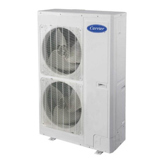
Multi-zone ductless split system sized 48 to 56
Hide thumbs
Also See for 38GJ Series:
- Owner's manual & installation instructions (12 pages) ,
- Owner's manual & installation instructions (22 pages)
Table of Contents
Advertisement
Quick Links
38
Ductless Split System
Sizes
to
Owner's Manual
Please read this Owner's Information Manual carefully before installing and using this appliance
and keep this manual for future reference.
For your convenience, please record the model and serial numbers of your new equipment in the
spaces provided. This information, along with the installation data and dealer contact information,
will be helpful should your system require maintenance or service.
UNIT INFORMATION
Model #
Serial #
INSTALLATION INFORMATION
Date Installed
the environmentally sound refrigerant
NOTE TO EQUIPMENT OWNER:
DEALERSHIP CONTACT INFORMATION
Company Name:
Address:
Phone Number:
Technician Name:
Advertisement
Table of Contents

Related Manuals for Carrier 38GJ Series


Summary of Contents for Carrier 38GJ Series
- Page 1 Ductless Split System Sizes Owner's Manual the environmentally sound refrigerant NOTE TO EQUIPMENT OWNER: Please read this Owner’s Information Manual carefully before installing and using this appliance and keep this manual for future reference. For your convenience, please record the model and serial numbers of your new equipment in the spaces provided.
-
Page 2: System Requirements
SAFETY CONSIDERATIONS CAUTION Installing, starting up, and servicing air- -conditioning equipment can be hazardous due to system pressures, electrical components, EQUIPMENT DAMAGE HAZARD and equipment location (roofs, elevated structures, etc.). Failure to follow this caution may result in equipment Only trained, qualified installers and service mechanics should damage or improper operation. -
Page 3: Table Of Contents
Contents Safety Precautions........................1 Attention for Installation......................3 Precautions for R410A....................3 Precaution for Installation .....................3 Precaution for Operation Test..................3 Accessories........................3 Product Introduction .........................4 Names of Main Parts.....................4 Combinations for Outdoor and Indoor Units ..............4 Parts and Components of Unit ..................5 Working Temperature Range..................5 Selection of Installation Location and Precautions ..............6 Selection of Installation Location .................6 Outline Dimension of Outdoor Unit................7... - Page 4 12 Troubleshooting ........................26 12.1 Check before Contacting Service Center ..............26 12.2 Problem Handling .......................27 12.3 Error Description......................27 13 Maintenance..........................30 13.1 Outdoor Condenser .....................30 13.2 Drain Pipe ........................30 13.3 Check before the Seasonal Use ...................30 13.4 Maintenance after Seasonal Use .................30...
- Page 5 Preface The total capacity of the indoor units which runs at the same time cannot exceed the capacity of the outdoor units; otherwise, the cooling (heating) effect of each indoor unit would be lower than the nominal capacity. Keep the operations manual for future reference and repair. The refrigerant pipes and accessories must be designed exclusively for R410A.
-
Page 6: Safety Precautions
long Connect the wired... - Page 7 maintain plugging or un pl ug gi ng child ren to Power Do not cut off the power for short periods of time, like 24 hour periods, to protect the compressor. do not the indoor Faulty the abnormality continues...
-
Page 8: Attention For Installation
2 Attention for Installation 2.1 Precautions for R410A The refrigerant pipes should be clean and dry. The R410A is a mixed refrigerant. When adding it to the unit, the refrigerant must keep the be kept in its liquid state. If the refrigerant is in a gas state, the composition has been changed and the capability of the unit will decrease. -
Page 9: Product Introduction
3 Product Introduction The GJ System adopts inverter compressor technology. According to change displacement of the compressor, a stepless capacity regulation within range of 10% 100% can be realized. Various product lineups are provided with a capacity range from 14kW to 16kW, which can be widely used in residential, office, hotel and where applicable to a site with a variable load change. -
Page 10: Parts And Components Of Unit
Table 2 Outdoor Model Indoor Unit Nominal Unit Btuh Indoor Model Number Number 9,000 40GJQB09B--3 12,000 40GJQB12B--3 High Wall 40GJ*B 18,000 40GJQB18B--3 24,000 40GJQB24B--3 9,000 40GJQB09D--3 12,000 40GJQB12D--3 Ducted 40GJ*D 18,000 40GJQB18D--3 38GJQK48---3 21,000 40GJQB21D--3 38GJQL56---3 24,000 40GJQB24D--3 9,000 40GJQB09F--3 Floor Console 12,000 40GJQB12F--3... -
Page 11: Selection Of Installation Location And Precautions
118.4℉(48℃)/- 64.4℉(-18℃)/- 75.2℉(24℃)/- 68℉(-20℃)/- 4 Selection of Installation Location and Precautions ------------------------------------------------------------------------------------------------------------------------- Caution! The installation of the air conditioner must be in accordance with the national and local laws and regulations. The quality of the installation will affect the capability of the air conditioner. The installation should be performed by an authorized professional from an appointed service center. -
Page 12: Outline Dimension Of Outdoor Unit
4.2 Outline Dimension of Outdoor Unit 22 1/2 in (572 mm) 5 1/2 in (140 mm) 35 3/7 in (900 mm) Fig. 3 (unit: in/mm) 4.3 Installation and Servicing Space When the installation location is exposed to strong wind When strong winds of convert to feet or more exist at the installation site, the unit outlet cannot face the wind. -
Page 13: Installation Instruction
5 Installation Instruction Check the installation location and ensure the strength and level, so the unit will not cause any operating vibration or noise after installation. In accordance with the foundation drawing in the following figure, drill 4 holes in the installation location. -
Page 14: Installation Of Refrigerant Pipes
6 Installation of Refrigerant Pipes 6.1 Allowable Length and Drop Height of the Connecting Pipe Fig. 8 (8 indoor units) Table 4 Length ft/m The sorts The pipes Total length between outdoor unit and 180.4 ft (55 mm) L1+L2+L3+L4+L5 Branch Unit modules Total length 38GJQK48---3 262.5 ft (80 mm) -
Page 15: Dimension Of Connecting Pipe
Dimension of Connecting Pipe Table 5 Gas Pipe (in/mm) Liquid Pipe (in/mm) Sorts 38GJQK48---3 5/8 in (15.9 mm) 3/8 in (9.52 mm) Outdoor unit 38GJQL56---3 Between outdoor unit and the 3/4 in (19.05 mm) 3/8 in (9.52 mm) The pipe L1 1st branch Between the 1st and the 2nd 5/8 in (15.9 mm) -
Page 16: Oil Trap Design Requirements
6.4 Oil Trap Design Requirements If the height difference between the indoor and outdoor units exceed 19.7ft (6m), install an oil trap every 19.7ft (6m)from the lower to the upper section of the vertical gas pipe. Fabricate the oil trap into two U-type elbows or one return-type elbow. - Page 17 ⑤. Refer to the schematics below. The outdoor unit is lower than the indoor unit. Branch Unit 1 Branch Unit 1 The outdoor unit is higher than the indoor unit. Branch Unit 1 Branch Unit 1...
-
Page 18: Connection Of Refrigerant Pipes
6.5 Connection of Refrigerant Pipes 6.5.1 Precautions for connection Pipe connections should be installed based on the following rules: Outdoor unit should be installed near the indoor unit to minimize the length and bends of connection pipes. The height gap of outdoor unit and indoor units should be as small as possible The brazing operation must be performed strictly in accordance with the process requirements. -
Page 19: Connection Of Refrigerant Pipe
The following table for the torque required to tighten the nuts. 1/4 in (6.35 mm) 1/30 in (0.8 mm) 20.34~40.68 ft. lb(15~30 N.m) 3/8 in (9.52 mm) 47.46~54.24 ft. lb(35~40 N.m) 1/30 in (0.8 mm) 1/2 in (12.7 mm) 1/30 in (0.8 mm) 61.02~67.8 ft. -
Page 20: Leak Test
Name Coping plate Rear side plate Front side plate Gas side stop valve Name Liquid side stop valve Right connection board Front connection board Name Front connection Bottom connection Side connection Rear connection Fig. 15 Unscrew the coping plate, front side plate, right connection board and front connection board. The refrigerant pipes can be installed in four directions, choose the proper direction. -
Page 21: Refrigerant Charging
1: Outdoor unit 2: Liquid side stop valve 3: Gas side stop valve 4: Pressure-vacuum gauge 5: Hi-knob 6: Lo-knob 7: Vacuum pump Fig. 17 Turn off the knobs first and then the pump. If the pressure of the pressure-vacuum gauge does not rise within 2 hours, the system is under a vacuum, otherwise, the system has leaked, so look for the gas leaks . - Page 22 Table 7 Serial No. Model 40GJQB12C--3 Indoor unit 1 Cassette type 40GJQB09D--3 Indoor unit 2 Duct type 40GRQB09B--3 Indoor unit 3 Wall mounted type 40GJQB09B--3 Indoor unit 4 Wall mounted type 40GJQB09D--3 Indoor unit 5 Duct type 40GJQB09B--3 Indoor unit 6 Wall mounted type Table 8 (in /mm)
- Page 23 Outdoor Liquid side stop Gas side stop Pressure-vacuum Name Service port unit valve valve gauge Name Hi-knob Lo-knob R410A tank Scale Fig. 19 When the liquid and gas stop valves have not been opened, the system is under the vacuum: a....
-
Page 24: Electrical Wiring Work
7 Electrical Wiring Work 7.1 Wiring Connection The “L1”, “3” terminals are connected to the live wire, the “L2”,”N(1)” terminals are connected to the neutral wire and the ”2” terminal is connected to the transmission line. Fig. 20 7.2 Requirements of Power Circuit and Cable Table 10 Phase and frequency 1Ph,60Hz... -
Page 25: Ground Requirements
The specifications of the power cable listed in the table above are applied to the conduit-guarded multi-wire copper cable (for example, YJV copper cable, consisting of PE insulated wires and a PVC cable jacket) used at and resistible to 194°F (90°C) , and shall be at least those of 104°F 40°C) -
Page 26: Precaution Of Laying Wires
7.5 Precaution of Laying Wires Use a wire stripper to strip off a length of the insulation layer at the end of the wires. Loosen the screws on the terminal block of the air conditioner. Press the ends of the cable tightly onto the round terminals corresponding to the size of the screws. -
Page 27: Design Of Drainage Pipeline
8 Design of Drainage Pipeline 8.1 Installation of Drain Hose Choose one drain hole in the bottom of the outdoor unit. Connect the drain hose to the drain hole. The drain hose should be kept at 5~10 degrees of gradient to facilitate discharge of the condensing water. -
Page 28: Installation Of Protective Layer
9 Installation of the Protective Layer The refrigerant pipes should be insulated by the heat insulation material and plastic tape to prevent water condensation and leakage. Do not use the foam on the branch pipe for heat insulation. or more; Thickness of 0.35 in (9 mm) or more. 212°F (100°C) The heat insulation material: Heat resistance to... -
Page 29: Test Operation
10 Test Operation 10.1 Check after Installation Table 11 Items to be checked Possible malfunction Has it been fixed reliably? The unit may drop, vibrate or make noise. Has the gas leakage been checked? It may cause insufficient cooling(heating) capacity. Is the thermal insulation of the unit sufficient? It may cause condensation and dripping. -
Page 30: Testing Board Introduction
11 Testing Board Introduction 11.1 Compose of the Testing Board The testing board is in front of the electrical box and is quite visible. The testing board has the following advantages: detects indoor unit numbers and indoor unit address, displays real running functionality and detects code automatically. -
Page 31: Troubleshooting
12 Troubleshooting ------------------------------------------------------------------------------------------------------------------------- Caution! In the event of abnormal conditions (i.e. burning smell or unusual odor) , shut off the power supply immediately and contact the appointed service center. If the air conditioning continues to run abnormally, it may cause electric shock or a fire hazard. Do not repair the air conditioning personally. -
Page 32: Problem Handling
12.2 Problem Handling The conditions listed below are not classified as errors. Conditions Causes When restarting the unit soon after The overload protection switch of the unit delays The unit does it is stopped the startup for three minutes not run The unit will stand by for approximate one As soon as power supply is on minute... - Page 33 Memory card error Flash 16 times Compressor demagnetizing Flash 17 times protection Compressor desynchronizing Flash 18 times Compressor phase lack Flash 19 times Compressor phase circuit detection Flash 20 times error Compressor power protection Flash 21 times Compressor overload protection Flash 22 times Compressor discharge temperature Flash 23 times...
- Page 34 Indoor unit 6 is connected Flash 10 times Indoor unit 7 is connected Flash 11 times Indoor unit 8 is connected Flash 12 times Indoor unit 9 is connected Flash 13 times Indoor unit anti-freeze protection Indoor temperature sensor error Indoor evaporator midway temperature sensor error Temperature sensor error for liquid...
-
Page 35: Maintenance
13 Maintenance Inspection, , maintenance and care regularly should be performed by professional personnel, which will prolong the unit service life. 13.1 Outdoor Condenser The outdoor condenser must be cleaned every two months. Use a vacuum cleaner with a nylon brush to clean up dust and debris on the surface of the condenser. - Page 36 Catalog No: 38GJ-48-56-01OM Copyright 2014 Carrier Corporation S 7310 W. Morris St. S Indianapolis, IN 46231 Edition Date: 11/14 Replaces: New Manufacturer reserves the right to change, at any time, specifications and designs without notice and without obligations.
Need help?
Do you have a question about the 38GJ Series and is the answer not in the manual?
Questions and answers