
Related Manuals for Buderus RC20


Summary of Contents for Buderus RC20
- Page 1 – 7 747 006 248 08/2006 GB For heating engineers Installation and service instructions RC20 room controller Please read carefully prior to commissioning or servicing.
-
Page 2: Table Of Contents
..... 25 We reserve the right to make any changes due to technical modifications. Installation and service instructions RC20 room controller • Issue 08/2006... -
Page 3: Installation And Service Instructions Rc20 Room Controller • Issue 08/2006
........30 We reserve the right to make any changes due to technical modifications. Installation and service instructions RC20 room controller • Issue 08/2006... -
Page 4: Safety Instructions And User Notes
Safety instructions and user notes Safety instructions and user notes Correct use The RC20 room controller may only be used to operate and control Buderus heating systems in houses and flats. The boiler must be equipped with EMS (energy management system) or UBA1.x (universal burner control). -
Page 5: System Handover
We recommend that these installation and service instructions are handed over to the customer and stored in the vicinity of the heating system. We reserve the right to make any changes due to technical modifications. Installation and service instructions RC20 room controller • Issue 08/2006... -
Page 6: Other Notes
Installation, maintenance and repairs as well as fault diagnosis may only be carried out by authorised and qualified personnel. Only use the RC20 room controller in combination with the accessories and spare parts specified in these instructions. Use alternative accessories and wearing parts only if these are... -
Page 7: Specifications
EN 50081-1, EN 61000-3-2, (EMC emission) EN 61000-3-3 EMC immunity EN 60730-1, EN 61000-6-2 Tab. 2 Applicable product standards We reserve the right to make any changes due to technical modifications. Installation and service instructions RC20 room controller • Issue 08/2006... -
Page 8: Installation
Alternative heat sources (sunlight or other heat sources, such as an open fire) in the reference room affect the control function of the RC20. If there are alternative heat sources in the reference room, rooms without alternative heat sources may be too cold. - Page 9 Installation 3.2.2 Installation position Choose an internal wall in the reference room and install the RC20 room controller as shown in Fig. 1. The clearance below the room controller and the distance from the door are important in order to obtain accurate measurement results.
-
Page 10: Installation And Connections
(if necessary pack the box with insulating material). We reserve the right to make any changes due to technical modifications. Installation and service instructions RC20 room controller • Issue 08/2006... - Page 11 When fitting to a flush-mounted box, use the vertical or horizontal fixing holes (Fig. 3, Item 3 or Item 4). We reserve the right to make any changes due to technical modifications. Installation and service instructions RC20 room controller • Issue 08/2006...
- Page 12 "EXT" (Fig. 4, Item 2) cable terminals. The "EXT" cable terminals have no function on the RC20 room controller. We reserve the right to make any changes due to technical modifications. Installation and service instructions RC20 room controller • Issue 08/2006...
- Page 13 Fig. 5 Fitting the RC20 room controller Hook the top of the RC20 room controller to the mounting plate in the direction shown by the arrow (Fig. 5, step 1). Push the bottom of the RC20 room controller against the mounting plate in the direction shown by the arrow until it clicks into place (Fig.
-
Page 14: Switching On And Off
"address" parameter is used to specify whether the room controller is to be installed as the sole programming unit or as a remote control unit. Press the pin button on the RC20 and enter the address (see section 5.4 "Address ", page 19). -
Page 15: Operating Tips
", page 19). Frost protection – If the RC20 room controller is installed as a remote control unit, the frost protection function can be set on the programming unit (e.g. RC30/RC35). – When the RC20 is the sole programming unit... -
Page 16: Service
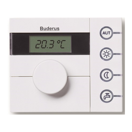
Pin button Item 1: Rotary selector Item 2: Pin button Item 3: Pin to press the pin button We reserve the right to make any changes due to technical modifications. Installation and service instructions RC20 room controller • Issue 08/2006... - Page 17 Press the "AUT" button or turn the rotary selector until "----" appears and then press the pin button. The standard display appears. We reserve the right to make any changes due to technical modifications. Installation and service instructions RC20 room controller • Issue 08/2006...
-
Page 18: Parameter Overview
Exiting the service level Tab. 3 Overview of parameters Not possible for operation on boilers with UBA 1.5. We reserve the right to make any changes due to technical modifications. Installation and service instructions RC20 room controller • Issue 08/2006... -
Page 19: Adjusting Parameters
"----" flashes in the display. USER NOTE All other parameters can be set in the same way. Address Use "address" (P1) to specify how the RC20 room controller is installed in the system (see the RC20 User Manual). Setting Explanation... -
Page 20: Heating System
Service Heating system If the RC20 room controller is the sole programming unit in the system (P1 = 0) or operation takes place using UBA 1.5, this parameter determines the type of control for the heating system (only room temperature dependent control is possible). -
Page 21: Room Temperature Compensation
If the RC20 room controller measures a temperature that is 0.1 °C below the value measured by the thermometer, then enter "+0.1 °C" as the calibration value. The RC20 room controller then displays a temperature that is 0.1 °C higher than the measured... -
Page 22: Pump Type 1)
(P1 ≠ 0). In this case, set the pump type on the RC30/RC35. Not possible for operation using boilers with UBA 1.5. We reserve the right to make any changes due to technical modifications. Installation and service instructions RC20 room controller • Issue 08/2006... -
Page 23: Pump Run-On Time
"----". – Time Not possible for operation using boilers with UBA 1.5. We reserve the right to make any changes due to technical modifications. Installation and service instructions RC20 room controller • Issue 08/2006... -
Page 24: Adjusting The Time
5.11 Adjusting the time If the clock tends to run fast or slow, this function can be used to correct it. If the clock in the RC20 room controller is slow, e.g. by two seconds a day, enter "2" as the correction value. -
Page 25: Pasteurisation Process
70 °C. During the pasteurisation process the circulating pump runs constantly. P9 is not shown if the RC20 is installed as a remote control unit (P1 ≠ 0). In this case, adjust the thermal disinfection on the programming unit (e.g. -
Page 26: Troubleshooting
Tab. 4 Fault table (system faults) Not possible for operation on boilers with UBA 1.5. We reserve the right to make any changes due to technical modifications. Installation and service instructions RC20 room controller • Issue 08/2006... - Page 27 Tab. 4 Fault table (system faults) Not possible for operation on boilers with UBA 1.5. We reserve the right to make any changes due to technical modifications. Installation and service instructions RC20 room controller • Issue 08/2006...
- Page 28 Buderus sales office. Refer to the boiler documentation for information on how to remedy other faults. We reserve the right to make any changes due to technical modifications. Installation and service instructions RC20 room controller • Issue 08/2006...
-
Page 29: Setup Report
P10 Software version – always Tab. 5 Setup report Not possible for operation using boilers with UBA 1.5. We reserve the right to make any changes due to technical modifications. Installation and service instructions RC20 room controller • Issue 08/2006... -
Page 30: Index
Thermometer, separate ..21 Master function ... . . 15 We reserve the right to make any changes due to technical modifications. Installation and service instructions RC20 room controller • Issue 08/2006... - Page 31 Notes We reserve the right to make any changes due to technical modifications. Installation and service instructions RC20 room controller • Issue 08/2006...
- Page 32 Your installer: Buderus BBT Thermotechnik GmbH Cotswold Way, Warndon, Worcester WR4 9SW D-35573 Wetzlar Tel.: 01905 752794, Fax: 01905 753130 www.heiztechnik.buderus.de www.buderus-commercial.co.uk info@heiztechnik.buderus.de In the UK, Buderus is a trading name of BBT Thermotechnology Ltd.
Need help?
Do you have a question about the RC20 and is the answer not in the manual?
Questions and answers