Pioneer PDR-509 Service Manual
Compact disc recorder
Hide thumbs
Also See for PDR-509:
- Operating instructions manual (128 pages) ,
- Service schematics (23 pages) ,
- Service manual (23 pages)
Table of Contents
Advertisement
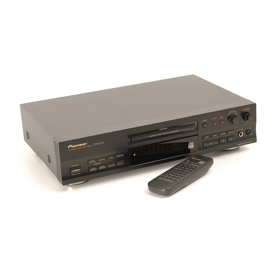
COMPACT DISC RECORDER
PDR-509
THIS MANUAL IS APPLICABLE TO THE FOLLOWING MODEL(S) AND TYPE(S).
Model
Type
PDR-509
KU/CA
MY
MV
This service manual should be used
together with the following manual (s).
Model
Order No.
PDR-509
RRV2055
CONTENTS
1. SAFETY INFORMATION ....................................... 2
2. EXPLODED VIEWS AND PARTS LIST ................. 4
4. PCB CONNECTION DIAGRAM ........................... 37
5. PCB PARTS LIST ................................................ 47
6. ADJUSTMENT ..................................................... 52
PIONEER CORPORATION
PIONEER ELECTRONICS SERVICE, INC. P.O. Box 1760, Long Beach, CA 90801-1760, U.S.A.
PIONEER ELECTRONIC (EUROPE) N.V. Haven 1087, Keetberglaan 1, 9120 Melsele, Belgium
PIONEER ELECTRONICS ASIACENTRE PTE. LTD. 253 Alexandra Road, #04-01, Singapore 159936
c
PIONEER CORPORATION 1999
Power Requirement
AC120V
AC220-230V
AC220-230V
Remarks
Service guide
4-1, Meguro 1-chome, Meguro-ku, Tokyo 153-8654, Japan
DIGITAL
REC LEVEL
INPUT
MONITOR
TIME
SELECTOR
REPEAT
FOR U.S. MODELS
NECESSARY INFORMATION FOR DHHS
RULES MARKED ON THE REAR BASE AND ON
THE TOP OF CD MECHANISM AS BELOW.
7. GENERAL INFORMATION .................................. 58
7.1 DIAGNOSIS ................................................... 58
7.1.1 TROUBLE SHOOTING ............................ 58
7.1.2 DISASSEMBLY ........................................ 59
7.1.3 DIAGNOSIS OF CD-R CORE ASSY ........ 61
7.2 PARTS ........................................................... 62
7.2.1 IC ............................................................. 62
7.2.2 DISPLAY .................................................. 68
7.3 EXPLANATION .............................................. 70
7.3.1 ERROR CODE ......................................... 70
8. PANEL FACILITIES AND SPECIFICATIONS ....... 72
ANALOG
REC LEVEL
ORDER NO.
RRV2167
Remarks
T - IZE AUG. 1999 Printed in Japan
Advertisement
Table of Contents

Related Manuals for Pioneer PDR-509


Summary of Contents for Pioneer PDR-509
-
Page 1: Table Of Contents
PIONEER CORPORATION 4-1, Meguro 1-chome, Meguro-ku, Tokyo 153-8654, Japan PIONEER ELECTRONICS SERVICE, INC. P.O. Box 1760, Long Beach, CA 90801-1760, U.S.A. PIONEER ELECTRONIC (EUROPE) N.V. Haven 1087, Keetberglaan 1, 9120 Melsele, Belgium PIONEER ELECTRONICS ASIACENTRE PTE. LTD. 253 Alexandra Road, #04-01, Singapore 159936 PIONEER CORPORATION 1999 T –... -
Page 2: Safety Information
The use of a substitute replacement component which does Leakage 0.5mA current Device not have the same safety characteristics as the PIONEER tester under recommended replacement one, shown in the parts list in test this Service Manual, may create shock, fire, or other hazards. - Page 3 PDR-509 IMPORTANT LASER DIODE CHARACTERISTICS THIS PIONEER APPARATUS CONTAINS MAXIMUM OUTPUT POWER: 23 mW LASER OF CLASS ΙΙΙ b. WAVELENGTH: 778 – 787 nm SERVICING OPERATION OF THE APPARATUS S H O U L D B E D O N E B Y A S P E C I A L L Y INSTRUTED PERSON.
-
Page 4: Exploded Views And Parts List
See Contrast table (2) Accessory Spacer PHC1093 11 (2/2) 11 (1/2) MV Type Only (2) CONTRAST TABLE PDR-509/KU/CA, MY and MV are constructed the same except for the following : Part No. Mark No. Symbol and Description Remarks KU/CA Type MY Type... - Page 5 PDR-509 2.2 EXTERIOR SECTION Refer to KU/CA Type Only "2.4 CD-R CORE ASSY (1/2)", "2.5 CD-R CORE ASSY (2/2)". KU/CA Type Only MY Type Only MV Type Only MY Type Only Refer to "2.3 FRONT PANEL SECTION".
- Page 6 BBZ30P080FCC Caution Label See Contrast table (2) Disc Caution Label See Contrast table (2) (2) CONTRAST TABLE PDR-509/KU/CA, MY and MV are constructed the same except for the following : Part No. Mark No. Symbol and Description Remarks KU/CA Type...
- Page 7 Getter Label See Contrast table (2) CD-R Getter PRW1547 19P Flexible Cable/60V PDD1196 (2) CONTRAST TABLE PDR-509/KU/CA, MY and MV are constructed the same except for the following : Part No. Mark No. Symbol and Description Remarks KU/CA Type MY Type...
- Page 8 PDR-509 2.4 CD-R CORE ASSY (1/2) • Bottom View Refer to "2.5 CD-R CORE ASSY (2/2)". • CD-R CORE ASSY (1/2) PARTS LIST Mark No. Description Part No. Mark No. Description Part No. LOADING A Assy PWZ3760 Drive Cam VNL1736...
- Page 9 PDR-509 2.5 CD-R CORE ASSY (2/2) • CD-R CORE ASSY (2/2) PARTS LIST Mark No. Description Part No. SERVO MECHANISM Assy PWZ3759 DC Motor Assy (SPINDLE) PEA1235 DC Motor (CARRIAGE) PXM1042 Float Rubber A AEB7063 Float Rubber B AEB7066 Rack Spring...
-
Page 10: Block Diagram And Schematic Diagram
PDR-509 3. BLOCK DIAGRAM AND SCHEMATIC DIAGRAM 3.1 BLOCK DIAGRAM : AUDIO SIGNAL ROUTE (RF) CD-R CORE Disc (CD, CD-R, CD-RW) IC431 34.5744MHz ASSY IC181 PDK041A 17.2872MHz NJM2137M STRATEGY RF AMP CIRCUIT CONTROL IC CN101 A–D RFDC 17.2872MHz IC401 IC251-IC254... - Page 11 PDR-509 INPUT JA801 JA401 L ch AUDIO ASSY VR801 IC401 REC VR KU/CA : PCM1716E IC404 OUTPUT HEADPHONE ASSY MY, MV : PE8001A DA CONVERTER R ch VR ASSY IC801 IC802 PCM1800-1 JA403 AD CONVERTER PHONES 13 14 15 IC406...
- Page 12 PDR-509 3.2 OVERALL WIRING DIAGRAM DIGITAL OUT DIGITAL IN KU/CA : 120V MY, MV : AC220-230V COAXIAL OPTICAL COAXIAL OPTICAL AC POWER CORD KU/CA : ADG7021 J651 MY : ADG1127 MV : ADG7004 DIGITAL I/O ASSY (KU/CA : PWZ4020) KU/CA : AKP1122...
- Page 13 PDR-509 Note : When ordering service parts, be sure to refer to "EXPLODED VIEWS and PARTS LIST" or "PCB PARTS LIST". HEADPHONE ASSY (PWZ3988) J403 LINE IOUT LINE IN CONTROL IN 1/2, AUDIO ASSY (KU/CA : PWZ3996) (MY, MV : PWZ3997)
- Page 14 PDR-509 3.3 CD-R CORE ASSY (1/5) CD-R CORE ASSY (PYY1273) • MECHA. CONTROL µCOM BLOCK ATIP DECODER...
- Page 15 PDR-509 8 bit LATCH 8 9 10 11 12 MECHA µ-COM EEPROM IC303 PYY1196 (BR93LC46F) L302,L305-L309, L311-L315,L318,L319 :OTL1040 CN301 CN804...
- Page 16 PDR-509 3.4 CD-R CORE ASSY (2/5) and CD-R PICKUP CD-R CORE ASSY (PYY1273) • RF PROCESSOR BLOCK CD-R PICKUP CN101 (PEA1351) MULTI PLEXER MULTI PLEXER...
- Page 17 PDR-509 : RF SIGNAL ROUTE : AUDIO SIGNAL ROUTE (REC) CN102 RF PROCESSOR...
- Page 18 PDR-509 3.5 CD-R CORE ASSY (3/5) CD-R CORE ASSY (PYY1273) • SERVO BLOCK...
- Page 19 PDR-509 MULTI PLEXER CDR SERVO AMP...
- Page 20 PDR-509 3.6 CD-R CORE ASSY (4/5) CD-R CORE ASSY (PYY1273) • DIGITAL BLOCK D-RA EFM ENCODER IC STRATEGY CONTROL...
- Page 21 PDR-509 : AUDIO SIGNAL ROUTE : AUDIO SIGNAL ROUTE (REC) : The power supply is shown with the marked box. D-RAM 16.9344MHz CN501 FS CONVERTER CN801 L511-L513,L515-L518, MULTI PLEXER L522,L524,L526 : OTL1040 F510,F514,F520 F521,F527 : VTH1097...
- Page 22 PDR-509 3.7 CD-R CORE (5/5), SERVO MECHANISM, LOADING A and LOADING B ASSYS CD-R CORE ASSY (PYY1273) • DECODER BLOCK 5ch ACTUATOR DRIVER CN453 CN451 CN452 LOADING A CN501 S501 ASSY (PWZ3760) LOADING B ASSY (PWZ3761) LOADING MOTOR CN551 ASSY...
- Page 23 PDR-509 CD DECODER CN901 : RF SIGNAL ROUTE : AUDIO SIGNAL ROUTE : The power supply is shown with the marked box.
- Page 24 PDR-509 3.8 AUDIO (1/2) and HEADPHONE ASSYS J651 CN802 CN501 PS80503 AUDIO ASSY (KU/CA : PWZ3996) (MY, MV : PWZ3997) • D/A BLOCK KU/CA : PCH1141 MY, MV : PCH1122 D/A CONVERTER KU/CA : PCM1716E MY, MV : PEB8001A PS80503...
- Page 25 PDR-509 : The power supply is shown with the marked box. : AUDIO SIGNAL ROUTE : AUDIO SIGNAL ROUTE (REC) PS80503 JA402 PS80503 CONTROL IN ∗ : R413-R416 RN1/10SE ∗ KU/CA : PCH1142 MY, MV : PCH1128 JA401 (1/2) KU/CA : PCH1142...
- Page 26 PDR-509 3.9 AUDIO (2/2) and VR ASSYS AUDIO ASSY (KU/CA : PWZ3996) (MY, MV : PWZ3997) • A/D BLOCK JA801 (1/2) LINE IN CN803 LINE IN JA801 (2/2) VR ASSY (PWZ3992) ANALOG REC VOLUME J851 CN806 : The power supply is shown with the marked box.
- Page 27 PDR-509 CN805 CN301 CN701 CN804 VKN1246...
- Page 28 PDR-509 3.10 DIGITAL I/O ASSY DIGITAL IN JA651 JA652 DIGITAL IN DIGITAL OUT JA653 KU/CA : PCH1143 MY, MV : 100/50 DIGITAL OUT JA654...
- Page 29 PDR-509 DIGITAL I/O ASSY (KU/CA : PWZ4020) (MY, MV : PWZ4021) : The power supply is shown with the marked box. CN802 J651 D20PYY0605E...
- Page 30 PDR-509 3.11 OPERATING ASSY OPERATING ASSY (KU/CA : PWZ3977) (MY, MV : PWZ3978) FL HOLDER J701 KU/CA ONLY CN51 100/10 51048-0600 MY, MV ONLY...
- Page 31 PDR-509 : The power supply is shown with the marked box. CN805 CN701 KU/CA ONLY MY, MV ONLY MODE CONTROLLER SYSTEM RESET 51048-0300 51048-0300 J703 J703A J703 D20PYY0315E...
- Page 32 PDR-509 3.12 POWER SUPPLY and REG ASSYS KU/CA : AKP1122 AC IN MY, MV : AKP7005 POWER SUPPLY ASSY (KU/CA : PWZ4008) (MY, MV : PWZ4009) 10000pF POWER POWER TRANSFORMER KU/CA : 0.01 MY, MV : 0.012 KU/CA : PTT1356 MY, MV : PTT1357 KU/CA : 0.01...
- Page 33 PDR-509 KU/CA : 100/35 MY, MV ONLY CN51 MY, MV : 220/35 J701 KU/CA : 0.01 MY, MV : 0.027 KU/CA : 0.01 MY, MV : 0.027 CN402 GNDSN KU/CA : PDF1201 MY, MV : PDF1199 CN21 B6B-PH-K-S MY, MV ONLY...
- Page 34 PDR-509 VOLTAGES and WAVEFORMS Note : The encircled numbers denote measuring point in the schematic diagram. CD-R CORE ASSY DGAI D8CM Media Pickup Position CD-R CORE ASSY (IC351-pin56) (IC351-pin57) 12cm Inner CN301 - pin 5 (MREQ) CN301 - pin 13 (MSI) V: 0.2V/div.(10 : 1) H: 5msec/div.
- Page 35 PDR-509 CD-R CORE ASSY CD-R CORE ASSY CN102 - pin 1 (RF) TP113 (RFAC) TP210 (FG) V: 20mV/div.(10 : 1) H: 0.5µsec/div. V: 0.2V/div.(10 : 1) H: 0.2µsec/div. V: 0.2V/div.(10 : 1) H: 1msec/div. (PLAY) (PLAY) (PLAY) CN102 - pin 3 (MPP)
- Page 36 PDR-509 CD-R CORE ASSY CD-R CORE ASSY CN501 - pin 2 (ADBCK) CN501 - pin 14 (DABCK) IC501 - pin 88 (EFM) CN452 - pin 2 (SL +) V: 0.2V/div.(10 : 1) H: 0.2µsec/div. V: 0.2V/div.(10 : 1) H: 0.2µsec/div.
-
Page 37: Pcb Connection Diagram
PDR-509 4. PCB CONNECTION DIAGRAM 4.1 SERVO MECHANISM, LOADING A and LOADING B ASSYS NOTE FOR PCB DIAGRAMS : 1. Part numbers in PCB diagrams match those in the schematic 3. The parts mounted on this PCB include all necessary parts for diagrams. - Page 38 PDR-509 4.2 CD-R CORE ASSY • This PCB is a four-layered board. CD-R CORE ASSY CN551 CN501 CN601 CN21 CN804 CD-R PICKUP CN801 (PNP1465-B) VR164 VR161 VR141 VR162 VR163 VR101 IC361-IC364 IC303 IC931-IC933 IC302 IC305 IC351 IC371 Q301 IC301 IC304...
- Page 39 PDR-509 • This PCB is a four-layered board. CD-R CORE ASSY (PNP1465-B) Q551 Q202 IC255 IC505 IC508 IC181 Q102 IC561 IC141 IC161 Q103 Q141 SIDE B...
- Page 40 PDR-509 4.3 AUDIO, HEADPHONE and VR ASSYS AUDIO ASSY Q405-Q408 Q401 IC404 Q402 IC801 IC401 IC402 CN501 Q801 IC802 IC451 CN301 IC803 CN701 (PNP1466-A) (PNP1466-A) (PNP1466-A) HEADPHONE ASSY VR ASSY SIDE A E F G...
- Page 41 PDR-509 AUDIO ASSY Q409 Q404 Q403 IC406 (PNP1466-A) (PNP1466-A) (PNP1466-A) VR ASSY HEADPHONE ASSY SIDE B E F G...
- Page 42 PDR-509 4.4 OPERATING ASSY OPERATING ASSY Q705 IC702 CN805 OPERATING ASSY IC701...
- Page 43 PDR-509 (PNP1466-A) CN51 SIDE A (PNP1466-A) Q701-Q704 SIDE B...
- Page 44 PDR-509 4.5 POWER SUPPLY and REG ASSYS AC IN POWER SUPPLY ASSY IC33 IC31 IC35 IC32 IC36 CN402 POWER TRANSFORMER IC25 IC23 IC22 CN901 (PNP1466-A) REG ASSY J701 SIDE A IC24 IC21...
- Page 45 PDR-509 POWER SUPPLY ASSY (PNP1466-A) REG ASSY SIDE B...
- Page 46 PDR-509 4.6 DIGITAL I/O ASSY DIGITAL I/O ASSY CN802 (PNP1466-A) IC651 IC652 SIDE A DIGITAL I/O ASSY (PNP1466-A) Q651 SIDE B 150%...
-
Page 47: Pcb Parts List
PDR-509 Mark No. Description Part No. Mark No. Description Part No. 5. PCB PARTS LIST • NOTES: Parts marked by "NSP" are generally unavailable because they are not in our Master Spare Parts List. • mark found on some component parts indicates the importance of the safety factor of the part. - Page 48 PDR-509 Mark No. Description Part No. Mark No. Description Part No. L568 CHIP SOLID INDUCTOR QTL1015 C133,C153,C254,C303,C322 CKSQYF103Z50 F401,F403,F432,F433 VTF1097 C362,C416,C433,C519 CKSQYF103Z50 CHIP SOLID INDUCTOR C521,C522,C555,C561,C562 CKSQYF103Z50 F501-F504,F506-F508,F510 VTF1097 C568,C569,C905 CKSQYF103Z50 CHIP SOLID INDUCTOR C106,C108,C111,C120,C123 CKSQYF104Z25 F514,F520,F521,F527 VTF1097 C125,C129,C132,C143,C152 CKSQYF104Z25...
- Page 49 PDR-509 Mark No. Description Part No. Mark No. Description Part No. C471,C472,C817,C821 CEAT470M25 LOADING A ASSY C815,C816 CEAT4R7M50 C413 CKSQYB102K50 SWITCH C885,C888-C890,C893 CKSQYB103K50 C408,C409,C818,C822,C875 CKSQYB104K25 S501 VSK1011 C403,C404 CKSQYB473K50 OTHERS C805 CKSQYF473Z50 CN501 KR CONNECTOR S3B-PH-K-S C427,C428 CQMBA102J50 C423,C424,C433,C434 CQMBA152J50...
- Page 50 PDR-509 Mark No. Description Part No. Mark No. Description Part No. OPERATING ASSY VR ASSY (1) CONTRAST TABLE RESISTORS VR801 VARIABLE PCS1016 PWZ3977 and PWZ3978 are constructed the same except Other Resistors RS1/10S for the following : Part No. Symbol and...
- Page 51 PDR-509 Mark No. Description Part No. Mark No. Description Part No. SCREW BBZ30P080FZK POWER SUPPLY ASSY JUMPER WIRE 6P D20PYY0610E JUMPER WIRE 8P D20PYY0830E (1) CONTRAST TABLE EARTH LEAD UNIT PDF1201 PWZ4008 and PWZ4009 are constructed the same except PCB BINDER...
-
Page 52: Adjustment
PDR-509 6. ADJUSTMENT 6.1 DISCS TO BE USED 6.3.2 Operations in Test Mode In Test mode, the following adjustment functions are assigned to 1. When adjusting the servo system adjustment the buttons, as explained below. CD : Test disc for adjustment (STD-903 or equivalent) ¶... -
Page 53: Danger - Laser Radiation When Open
PDR-509 6.4 ADJUSTMENT 1 (LASER DIODE POWER ADJUSTMENT) CD-RW record power CD-R CORE ASSY CD-R overdrive CD-R record power Playback power CD-RW bias power Playback CD-R recording CD-RW recording CN102 CD-RW erase power Fig.5 Output power of the laser diode... - Page 54 PDR-509 DANGER – LASER RADIATION WHEN OPEN. AVOID DIRECT EXPOSURE TO BEAM. 6.4.2 CD-R Record Power Adjustment Test Point Pickup objective lens Adjustment Point VR163 (R REC), VR162 (R O.D.) VR163 : 4.60 mW ± 0.1 mW Adjustment Value VR162 : Addition of 0.1 mW ± 0.01 mW to the adjustment value of VR163 [Procedure] (1) Turn VR163 and VR162 completely counterclockwise to set their power output to minimum.
- Page 55 PDR-509 6.5 ADJUSTMENT 2 (SERVO SYSTEM ADJUSTMENT) CD-R CORE ASSY For servo adjustment, set the INPUT SELECTOR to OPTICAL. INPUT MONITOR SELECTOR CN102 Use the DIGITAL REC LEVEL Knob to make the adjustments. DIGITAL REC LEVEL 1 : RF 2 : VC...
- Page 56 PDR-509 6.5.2 M-S Mix Ratio Adjustment Test Point CN102 - pin 4 (TE) and pin 3 (MPP) Test Disc STD-903 Adjustment Point DIGITAL REC LEVEL knob Adjust until the value of the output signals from pin 4 (TE) and pin 3 (MPP) of CN102 are the same, Adjustment Value or the differential output of these signals is minimal.
- Page 57 PDR-509 6.5.4 Focus Bias Adjustment Test Point CN102 - pin 1 (RF) Test Disc STD-903 Adjustment Point DIGITAL SYNCHRO button, DIGITAL REC LEVEL knob Adjustment Value Adjust until RF jitter is minimal or that the eye pattern of the RF waveform is most open.
-
Page 58: General Information
PDR-509 7. GENERAL INFORMATION 7.1 DIAGNOSIS 7.1.1 TROUBLE SHOOTING Power isn't turn on. FL display isn't light up. FL display is abnormal. START POWER ON • IC1 (micro-fuse) fuses it. • A thermal-fuse of the power transformer fuses it. • IC701 (Mode Controller) breaks. -
Page 59: Disassembly
PDR-509 7.1.2 DISASSEMBLY Bonnet ×2 Bonnet ×2 ×2 PCB Location and Adjustment Points TEST MODE VR164 VR161 VR141 VR162 VR163 VR101 CD-R CORE OPERATING Assy Assy VR Assy REG Assy HEADPHONE Assy POWER AUDIO Assy SUPPLY Assy CN102 DIGITAL I/O Assy... - Page 60 PDR-509 CD-R CORE ASSY • CD-R CORE Assy • Servo Mechanism Block ×3 Bridge Rear View CD-R CORE Assy CN502 CN301 CN901 Drive Gear Pull-up Front Side ×2 ×2 CD-R CORE Assy Tray ×3 CN451 CN453 CN452 CN101 CD-R CORE...
-
Page 61: Diagnosis Of Cd-R Core Assy
PDR-509 7.1.3 DIAGNOSIS OF CD-R CORE ASSY When diagnosing the CD-R CORE Assy, use the following Flexible Cable and Connector Assys for service. • Flexible Cable and Connector Assys for service CN101 ↔ CN1 (Pickup) 32P Flexible Cable : PDD1202 CN452 ↔... -
Page 62: Parts
PDR-509 7.2 PARTS 7.2.1 IC • The information shown in the list is basic information and may not correspond exactly to that shown in the schematic diagrams. • List of IC PE5109A, M56788FP, PCM1800-1, PE5110B PE5109A (CD-R CORE ASSY : IC301) •... - Page 63 PDR-509 n i l − − " : ( " x i f " ) " l a i l a i " " L " " L " " L − g i l g i l t i s −...
-
Page 64: Block Diagram
PDR-509 M56788FP (CD-R CORE ASSY : IC451) • 5 Channel Actuator Driver • Block Diagram VBS2 IN3- VBS1 8 IN3+ IN1+ 2 OUT3 IN1- OUT1 CH3IN VBS1 VBS2 Vrefm1 Vrefm2 VM1(+) VM3(+) ×5 ×8 VM1(-) VM3(-) VBS1 VBS2 VM2(+) VM4(+) VREFO ×8... - Page 65 PDR-509 PCM1800-1 (AUDIO ASSY : IC802) • A/D Converter • Block Diagram CINPL CINNL SINGLE-END 5 th ORDER SERIAL I/O /DIFFERENTIAL DELTA-SIGMA 13 LRCK INTERFACE CONVERTER MODULATOR ×1/64 12 FSYNC DECIMATION 15 DOUT FILTER REFCOM REFERENCE with 10 MODE0 DC CUT FILTER...
- Page 66 PDR-509 PE5110B (FUNCTION ASSY : IC701) • Mode Controller • Pin Function − − − " " L − " " L − " " L i g i l l o l a i l l o l a i...
- Page 67 PDR-509 l l o ↓ l l o " " L " " − − " " L c t i " ( " L g i l − −...
-
Page 68: Display
PDR-509 7.2.2 DISPLAY PEL1099 (FUNCTION ASSY : V701) • FL TUBE • Anode & Grid Assignment... - Page 69 PDR-509 • Pin Assignment...
-
Page 70: Explanation
Laser Hour Meter Indication and Error Code Display for Service Left 4 FL digits : Total turn-on time of the laser diode The PDR-509 can display the total turn-on time of the laser diode Right 2 FL digits : Error code for service and error codes for service. - Page 71 PDR-509 Code Symptom Contents of Error Possible Cause Checkpoints • Defective laser diode Defects related to the recording laser • Trouble in RF detection power IC201 (PA9007A) • Defective RFT RFB circuit The unit stops before it • Dirty or cracked disc IC101 (AK8563) C∗...
-
Page 72: Panel Facilities And Specifications
PDR-509 8. PANEL FACILITIES AND SPECIFICATIONS 8.1 PANEL FACILITIES Front Panel DIGITAL ANALOG REC LEVEL REC LEVEL INPUT MONITOR TIME REPEAT SELECTOR The illustration shows the U.S. model. 1 POWER switch w TRACK NUMBER AUTO/MANUAL Switches power to the unit on and off. - Page 73 PDR-509...
-
Page 74: Remote Control Unit
PDR-509 Remote Control Unit Press to pause playback or recording. Press to stop playback or recording. 7 1 and ¡ Press and hold for fast-reverse and fast-forward playback. 8 INPUT SELECTOR FADER FINALIZE Switches between the analog, optical digital and coaxial digital inputs. - Page 75 PDR-509 Display 1 RPT / RPT–1 q D.VOL Lights when disc repeat / track repeat mode is on. Lights when the digital volume control function is active. 2 PGM w AUTO TRACK Lights when program-play mode is active. Lights when automatic track numbering is on during 3 RDM recording.
-
Page 76: Specifications
PDR-509 8.2 SPECIFICATIONS NOTE: KU/CA Type The specifications and design of this product are subject to 1. General change without notice, due to improvements. Model ........Compact disc audio system Applicable discs ......CDs, CD-Rs and CD-RWs MY and MV Types Power supply .......... - Page 77 PDR-509 Accessories Two Sets of Audio Cords AC Power Cord (KU/CA Type) Two "AA" size R6P Batteries Remote Control Unit (PDE1249)(L = 1 m) (ADG7021) (VEM-013) CU-PD114 (PWW1163) White FADER FINALIZE DIGITAL AUTO/ TRACK NO. ERASE SYNCHRO MANUAL WRITE AC Power Cord (MV Type)
Need help?
Do you have a question about the PDR-509 and is the answer not in the manual?
Questions and answers