Carrier 42QHF009DS Service Manual
Dc inverter multi type
Hide thumbs
Also See for 42QHF009DS:
- Manual (28 pages) ,
- Owner's manual (8 pages) ,
- Installation manual (5 pages)
Table of Contents
Advertisement
DC INVERTER MULTI TYPE
1 / 78
Service Manual
AIR CONDITIONER
This manual applies to models:
High Wall
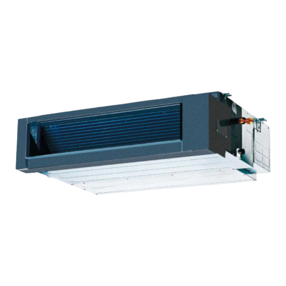
Duct
Cassette
Console
Universal CDU
42QHF009DS
42QHF012DS
42QHF018DS
42QSM009DS
42QSM012DS
42QSM018DS
42QTD009DS
42QTD012DS
42QTD018DS
42QFA009DS
42QFA012DS
42QFA018DS
38QUS018DS2
38QUS027DS3
38QUS036DS4
Advertisement
Table of Contents

Related Manuals for Carrier 42QHF009DS


Summary of Contents for Carrier 42QHF009DS
-
Page 1: Service Manual
Service Manual AIR CONDITIONER DC INVERTER MULTI TYPE This manual applies to models: 42QHF009DS High Wall 42QHF012DS 42QHF018DS 42QSM009DS Duct 42QSM012DS 42QSM018DS 42QTD009DS Cassette 42QTD012DS 42QTD018DS 42QFA009DS Console 42QFA012DS 42QFA018DS 38QUS018DS2 Universal CDU 38QUS027DS3 38QUS036DS4 1 / 78... -
Page 2: Table Of Contents
CONTENTS 1. General information of Outdoor& Indoor Units ........3 2. Features ....................4 3. Dimensions ..................11 4. Service space for light commercial indoor ........18 5. Wiring Diagram ..................20 6. Refrigeration Cycle Diagram .............. 25 7.Indoor units combination..............27 8. -
Page 3: General Information Of Outdoor& Indoor Units
Compressor 38QUS018DS2 845x320x700 DA130M1C-31FZ 38QUS027DS3 900x315x860 DA250S2C-30MT 38QUS036DS4 990x345x965 TNB306FPGMC-L ■Indoor High wall A5 Duct Four-way cassette (compact): Console: Model name Dimension (mm) 42QHF009DS 800x188x275 42QHF012DS 800x188x275 42QHF018DS 940x205x275 42QSM009DS 700x635x210 42QSM012DS 700x635x210 42QSM018DS 920x635x210 42QTD009DS 570x570x260 42QTD012DS 570x570x260 42QTD018DS... -
Page 4: Features
2. Features 2.1 Outdoor unit 2.2 High wall High wall Outdoor unit Filter Power relay control Low noise air flow system Low noise air flow system Refrigerant leakage detect Hydrophilic aluminum fin The hydrophilic fin can improve the heating efficiency at operation mode. 2 ways of drainage 4 way valve control It is only operated in the heating operation mode except defrosting operation. - Page 5 The body size is 570×260×570mm, it’s just smaller than the console board, so it’s very easy for installation and will not damage the decoration. The panel size is 647×50×647mm. The hooks are designed in the four corners of the body, which can save installation space. ⑶...
- Page 6 Fresh Dimension:Φ75mm ⑸ Air passage function Reserves the space for air outlet from the side of indoor unit; It’s availed to connect air duct from the two sides to the nearby small rooms. 6 / 78...
- Page 7 2.4 A5 Duct ⑴ Installation accessories: (Optional) Front Board, Canvas Air Passage, Filter, Panel, for easy installation Front Board Canvas Air Passage Filter Panel ⑵ Easy Installation: Two air inlet styles (Bottom side or Rear side) Air inlet from rear is standard for all capacity; air inlet from bottom is optional. ...
- Page 8 ⑷ Easy maintenance Clean the filter (Optional, standard product without filter) It is easy to draw out the filter from the indoor unit for cleaning, even the filter is installed in rear side or bottom side. Replace the motor or centrifugal fan Remove the ventilated panel firstly.
- Page 9 ⑹ Built-in drain pump (Optional): Built-in drain pump can lift the water to 750mm upmost. It’s convenient to install drainage piping under most space condition. ⑺ Built-in display board The standard indoor unit can be controlled by wired controller. ...
- Page 10 (3) Two direction auto swing (vertical & horizontal) and wide angle air flow, --Air flow directional control minimizes the air resistance and produces wilder air flow to vertical direction. --The range of horizontal air discharge is widened which secures wider air flow distribution to provide more comfortable air circulation no matter where the unit is set up (4) Three level fan speed, more humanism design, meets different air-supply requirement.
-
Page 11: Dimensions
3. Dimensions 3.1 Out door 38QUS018DS2 200.7 D1 335 560 W1 D2 360 845 W 11 / 78... - Page 12 38QUS027DS3 238.4 D1 333 590 W1 900 W D2 355 12 / 78...
- Page 13 38QUS036DS4 D1 366 624 W1 D2 397 990 W 13 / 78...
- Page 14 3.2 High wall Model 42QHF009DS / 42QHF012DS 42QHF018DS 14 / 78...
- Page 15 3.3 Four-way cassette (compact): Drain hole Gas side ( for Service ) Liquid side Body 4-install hanger 150 Distribution duct E-parts box 4-Screw hole (for install panel) Drain pipe Fresh air intake Wiring connection port Panel 15 / 78...
- Page 16 3.4 A5 Duct 16 / 78...
- Page 17 3.5 Console: a. Wall mounting installation Dimension Mode 42QFA009DS 42QFA012DS 42QFA018DS 17 / 78...
-
Page 18: Service Space For Light Commercial Indoor
4. Service space for light commercial indoor 4.1 Four-way cassette (compact) (unit: mm) 4.2 A5 Duct (unit: mm) Ensure enough space required for installation and maintenance . All the indoor units reserve the hole to joint the fresh air pipe. The hole size as following: 4.3 Console (unit: mm) 18 / 78... - Page 19 19 / 78...
-
Page 20: Wiring Diagram
5. Wiring Diagram Outdoor (38QUS018DS2) Outdoor (38QUS027DS3) 20 / 78... - Page 21 Outdoor (38QUS036DS4) High wall (42QHF009DS & 42QHF012DS & 42QHF018DS) 21 / 78...
- Page 22 A5 Duct (42QSM009DS) A5 Duct (42QSM012DS & 42QSM018DS) 22 / 78...
- Page 23 Four-way cassette (42QTD009DS) Four-way cassette (42QTD012DS & 42QTD018DS) 23 / 78...
- Page 24 Console 24 / 78...
-
Page 25: Refrigeration Cycle Diagram
Refrigeration Cycle Diagram 6.1 Refrigeration circuit drawing of 38QUS018DS2 INDOOR OUTDOOR EXV A CAPILIARY A LIQUID VALVE A CHECK VALVE EXV B CAPILIARY B LIQUID VALVE B Condenser temp. sensor CAPILIARY TUBE HEAT HEAT EXCHANGE T4 Ambient T1 Room EXCHANGE (EVAPORATOR) temp. - Page 26 INDOOR OUTDOOR EXV A CAPILIARY A LIQUID VALVE A EXV B CAPILIARY B LIQUID VALVE B CHECK VALVE EXV C CAPILIARY C LIQUID VALVE C Condenser temp. sensor EXV D CAPILIARY D CAPILIARY TUBE LIQUID VALVE D HEAT HEAT EXCHANGE T4 Ambient T1 Room EXCHANGE...
-
Page 27: Indoor Units Combination
7.Indoor units combination 7.1 Indoor unit combination for 38QUS018DS2 One unit Two unit 9+12 12+12 7.2 Indoor unit combination for 38QUS027DS3 One unit Two unit Three unit 12+18 9+9+9 9+12+12 9+12 12+18 9+9+12 12+12+12 9+18 18+18 9+9+18 7.3 Indoor unit combination for 38QUS036DS4 One unit Two unit Three unit... -
Page 28: Static Pressure (Duct)
8. Static Pressure (Duct) 7,000-12,000Btu/h External static pressure (Pa) 18,000Btu/h Super high speed High speed Mid speed Low speed 600 700 800 900 1000 1100 1200 Air volume(m /h) 28 / 78... -
Page 29: Operation Characteristics
9.Operation Characteristics Temperature Cooling operation Heating operation Mode Room temperature 17℃~32℃ 0℃~30℃ 0℃~50℃ (-15℃~50℃: For the Outdoor temperature -15℃~24℃ models with low temperature cooling system) CAUTION: 1. If the air conditioner is used beyond the above conditions, certain safety protection features may come into operation and cause the unit to operate abnormally. -
Page 30: Installation Details
10.Installation Details 10.1 Wrench torque sheet for installation Outside diameter Torque Additional tightening torque N.cm N.cm Ф6.35 1500(153kgf.cm) 1600(163kgf.cm) Ф9.52 2500(255kgf.cm) 2600(265kgf.cm) Ф12.7 3500(357kgf.cm) 3600(367kgf.cm) 10.2 Connecting the cables The power cord of connect should be selected according to the following specifications sheet. Rated current of appliance Nominal cross-sectional area (mm²... - Page 31 Indoor unit Extension pipe diameter (mm/inch) Model Pipe diameter (mm/inch) Liquid 6.35(1/4) Liquid 6.35(1/4) 9K/12K 9.52(3/8) 9.52(3/8) Liquid 6.35(1/4) Liquid 6.35(1/4) 12.7(1/2) 12.7(1/2) Outdoor unit union diameter (mm/inch) Liquid 6.35(1/4) Indoor unit A/B/C/D 9.52(3/8) 10.4 Installation for the first time Air and moisture in the refrigerant system have undesirable effects as below: ●...
- Page 32 (Indoor unit) (Outdoor unit) (Liquid side) Two-way valve Close (Gas side) Three-way valve Close Manifold valve Compound meter Pressure gauge -0.1MPa Handle Lo Handle Hi Charge hose Charge hose Vacuum pump Vacuum pump 1) Completely tighten the flare nuts of the indoor and outdoor units, confirm that both the 2-way and 3-way valves are set to the closed position.
- Page 33 2. Air purging by refrigerant Procedure: 1). Confirm that both the 2-way and 3-way valves are set to the closed position. 2). Connect the charge set and a charging cylinder to the service port of the 3-way valve. 3). Air purging. Open the valves on the charging cylinder and the charge set.
- Page 34 3. Adding the refrigerant if the pipe length >5m Electronic scale Procedure: 1). Connect the charge hose to the charging cylinder, open the 2-way valve and the 3-way valve. Connect the charge hose which you disconnected from the vacuum pump to the valve at the bottom of the cylinder.
- Page 35 Electronic scale Procedure: 1). Connect the charge hose to the 3-way service port, open the 2-way valve and the 3-way valve. Connect the charge hose to the valve at the bottom of the cylinder. If the refrigerant is R410A, make the cylinder bottom up to ensure liquid charge.
- Page 36 10.6 Re-installation while the indoor unit needs to be repaired 1. Collecting the refrigerant into the outdoor unit Procedure 1). Confirm that both the 2-way and 3-way valves are set to the opened position Remove the valve stem caps and confirm that the valve stems are in the opened position. Be sure to use a hexagonal wrench to operate the valve stems.
- Page 37 2. Air purging by the refrigerant Procedure: 1). Confirm that both the 2-way and 3-way valves are set to the closed position. 2). Connect the charge set and a charging cylinder to the service port of the 3-way valve Leave the valve on the charging cylinder closed. 3).
- Page 38 10.7 Re-installation while the outdoor unit needs to be repaired 1. Evacuation for the whole system Procedure: 1). Confirm that both the 2-way and 3-way valves are set to the opened position. 2). Connect the vacuum pump to 3-way valve’s service port. 3).
- Page 39 2. Refrigerant charging Procedure: 1). Connect the charge hose to the charging cylinder, open the 2-way valve and the 3-way valve Connect the charge hose which you disconnected from the vacuum pump to the valve at the bottom of the cylinder.
-
Page 40: Electronic Control Function
11.Electronic control function 11.1 Abbreviation T1: Indoor ambient temperature T2: Coil temperature of indoor heat exchanger middle. T2B: Coil temperature of indoor heat exchanger outlet. T3: Coil temperature of outdoor heat exchanger T4: Outdoor ambient temperature T5: Compressor discharge temperature T s: Setting temperature 11.2 Electric control working environment. - Page 41 11.4 Outdoor unit point check function There is a check switch in outdoor PCB. Press the switch N times it will display the content corresponding to No. N. After getting into the check function, it will display No. N with 1.5s, meanwhile the low bit decimal of digit display flashing, indicated to get into the check function display.
- Page 42 EXV open angle for A indoor unit Actual data/4. EXV open angle for B indoor unit If the value is higher than 99, the digital display tube will show single EXV open angle for C indoor unit digit and tens digit. For example, the digital display tube show “2.0”, it means the EXV EXV open angle for D indoor unit open angle is 120×4=480p.)
- Page 43 T1 Ts Capacity area Norm value (N) 11.4.4 Number of indoor unit Display Number of indoor unit 11.4.5 Opening degree of electronic expansion valve: Actual opening degree equals the display data times 4 11.5 Icon explanation on indoor display board 11.5.1 High wall DEFROST indication lamp(For cooling &...
-
Page 44: Main Protection
11.5.2 Four-way cassette (compact) 11.5.3 A5 Duct PRE-DEF indicator(cooling and heating type) or fan only indicator(cooling only type) Alarm indicator Timer indicator Infrared signal receiver Operation lamp Display digital tube Temporary button OPERATION TIMER DEF./FAN ALARM MANUAL 11.5.4 Console 11.6 Main Protection 11.6.1 Three minutes delay at restart for compressor. - Page 45 VOLTAGE No limit VOLT_RST1_ADD VOLT_LTM1_ADD VOLT_LTM_FREQ1_ADD VOLT_RST2_ADD VOLT_LTM2_ADD VOLT_LTM_FREQ2_ADD Note: if the low voltage protection occurs and not resumes within 3min, it will keep the protection always after restart the machine. 11.6.4 Compressor current limit protection If the compressor current exceeds the current limit value for 10 seconds, the compressor frequency will be limited as below table.
- Page 46 HEAT_F10 IHEATLMT6 HEAT_F9 IHEATLMT5 HEAT_F8 IHEATLMT4 HEAT_F7 IHEATLMT3 HEAT_F6 IHEATLMT2 HEAT_F5 IHEATLMT1 If the current frequency is lower than HEAT_F4, the frequency will not be limited. After 10s of the compressor start, if the current>IHEAT, the AC will display the failure for 30 seconds and stop. The AC will restart 3 minutes later.
- Page 47 (3) The louver operates same as in cooling mode. (4) Auto fan in fan-only mode acts as follow: For Console, A5 Duct: 27.5 High Medium 25.5 When T1-24≤27℃, transfer high to medium speed, When T1≤25℃, transfer medium speed to low. When T1>25.5℃, transfer low to medium speed, When T1>27.5℃, transfer medium speed to high.
- Page 48 …… Amendatory capacity demand. Meanwhile the maximum running frequency will be adjusted according to the outdoor ambient temp. T4LimFre5_ADD T4LimFre4_ADD T4LimFre3_ADD T4LimFre2_ADD T4LimFre1_ADD No limit 48 / 78...
- Page 49 11.7.2.2 Outdoor fan running rules Cooling Heating While A,B,C…means different fan speed of outdoor unit. 11.7.2.3 Indoor fan running rules (1) Indoor fan keeps running, fan speed can be set in high/mid/low/ Auto by using a remote controller: (2) Auto fan in cooling mode acts as follow: :...
- Page 50 High Medium (3) Anti-freezing control to indoor evaporator in cooling mode Evaporator Temp. Compressor T2≤ 4℃ Console, A5 duct T2> 8℃ four-way T2B<0℃ for 250s cassette (compact) T2B> 10℃ T2≤ 3℃ Off(After 3 minutes) The other types T2> 7℃ (4) PTC function is invalid and sleep mode can be set by using a remote controller. 11.7.2.4 Evaporator low temperature T2 protection When T2<4℃, the indoor has no capacity demand and resume till T2>8℃...
- Page 51 Heating 11.7.4.3 Indoor fan running rules (1) Indoor Fan actions in heating mode Indoor Fan can be set at HIGH/MID/LOW/AUTO by using a remote controller, but Anti-cold wind function prevails. Anti-cold wind control function in heating mode: (2) Auto wind in heating mode For Console: T1-Ts-ΔT Medium...
- Page 52 T1-Ts Medium High (3) Indoor evaporator high-temperature protection in heating mode For A5 duct, A3 four-way cassette (compact): T2>63℃, the compressor will stop and restart when T2<48℃. For the other types T2>60℃, the compressor will stop and restart when T2<48℃. 11.7.4.4 High evaporator coil temp.T2 protection: If T2>63℃, the indoor unit has no capacity demand and resume till 48℃.
- Page 53 Defrosting action: 4-Way valve no longer than 10min Compressor Cool-F9 TimeA 10S 30S Anti cold wind Indoor fan Outdoor fan PMV running 4 mins with 480P 480P 11.7.5 Auto-mode This mode can be chosen by remote controller and the setting temperature can be changed between 18~30℃.
- Page 54 Forced cooling mode: The indoor fan will work in low speed (For console, the indoor fan will work in breeze speed), compressor and outdoor fan open unconditionally, after 30mins, the unit will transfer into forced auto mode. All the protections are valid during forced cooling mode When there’s one indoor unit running in forced cooling, it is the master forced cooling unit.
- Page 55 When auto, After an hour running under economic mode ,if it is under cooling mode the set temp will rise 1℃, if it is under heating mode the set temp will decrease 1℃, if it is under fan-only mode the set temp will be changeless;...
- Page 56 Yes: Mode conflict (2) Unit action In case of one Indoor unit working in cooling mode or fan mode, and another indoor unit is set to heating mode, the indoor unit working in cooling mode or fan mode will change to off. The outdoor unit will change to heating mode after compressor stop 3 minutes.
-
Page 57: Troubleshooting
12.Troubleshooting 12.1 Indoor unit error code explanation: HIWALL (42QHF009DS, 42QHF012DS, 42QHF018DS) Display Operation lamp flash times Timer lamp Failure Indoor EEPROM malfunction Indoor / outdoor units communication error Indoor fan speed has been out of control Open or short circuit of T1 temperature sensor... - Page 58 ★ Indoor / outdoor units communication error ★ ★ Indoor EEPROM malfunction ★ ★ IPM module protection ★ ★ ★ Open or short circuit of T3 or T4 temperature sensor ★ ★ Outdoor unit voltage protection ★ Outdoor unit over-current protection ★...
- Page 59 12.3 Trouble shooting 12.3.1 For the indoor unit 12.3.1.1 Indoor EEPROM malfunction Shut off the power supply and turn it on 1 minute later. Is it still displaying the error code? If the EEPROM chip is welded on PCB, replace the PCB directly.
- Page 60 Indoor / outdoor units communication error Start: Power off , then Power on the A/C by the Breaker. (reconnect the power wire). Is it still displaying the error code? Check wiring on the outdoor and indoor terminal follow the wiring diagram. Is all Reconnect the wiring connecting correctly? Reconnect the wiring...
- Page 61 Operating Pic 1: check the voltage of N to S (Vs), is it moving Self-Check alternately between positive value and negative value? Pic 2:IPM or outdoor main PCB (For 38VNM218713) Pic 3: IPM or outdoor main PCB (For Power, 38VNM327713 / 38VNM436713) Self-Check Operating PIC 4 :Main board LED when power on and unit...
- Page 62 12.3.1.3 indoor unit fan speed has been out of control Power off, then restart the Power off, then restart the unit 2 minutes later. Is it still The unit operates normally. unit 2 minutes later. Is it still The unit operates normally. displaying the error code? displaying the error code? Find out the cause and...
- Page 63 DC motor voltage input and output For split type: Color Signal Voltage Vs/Vm 280V~380V Black White 14-17.5V Yellow 0~5.6V Blue 14-17.5V For other types: Color Signal Voltage Vs/Vm 192V~380V Black White 13.5-16.5V Yellow 0~6.5V Blue 13.5-16.5V 63 / 78...
- Page 64 12.3.1.4 Open or short circuit of temperature sensor. Check the connections Check the connections between temperature between temperature Correct the connections. Correct the connections. sensor and PCB. Are the sensor and PCB. Are the connections good? connections good? Measure the resistance value Measure the resistance value of the sensor via Appendix 1 of the sensor via Appendix 1...
- Page 65 12.3.2 For the outdoor unit 12.3.2 1 Outdoor EEPROM malfunction(ODU E0) Outdoor EEPROM malfunction If the EEPROM chip is welded on PCB, replace the PCB directly. Otherwise, Insert the EEPROM well check whether the EEPROM chip plugged in PCB well? Replace the outdoor main board EEPROM: An electrically erasable programmable read-only memory whose contents can be erased and reprogrammed using a pulsed voltage.
- Page 66 E3 display Communication malfunction between IPM board and outdoor main board Is there at least one LED in the IPM board light? Check the signal wire between the IPM board and the main board, is it connected good? Reconnect and retry. Is error still display? Replace IPM board, and then check whether the...
- Page 67 Voltage protection Check the voltage of outdoor unit power supply, whether the voltage Check the power supply between L(L1) and N (L2) is about 220~240VAC Check whether the voltage of IPM board P and N is normal? DC277-356V for 18-27KBtu/h; DC277-410V for 36-42KBtu/h Replace bridge rectifiers, and then check whether the...
- Page 68 12.3.2.4 Outdoor unit fan speed has been out of control (E8) Power off, then restart the Power off, then restart the unit 2 minutes later. Is it still The unit operates normally. unit 2 minutes later. Is it still The unit operates normally. displaying the error code? displaying the error code? Find out the cause and...
- Page 69 12.3.2.5 High pressure protection (ODU P1) (For 38QUS036DS4) High pressure protection High pressure protection Whether the wiring Whether the wiring between the high pressure between the high pressure switch and main control switch and main control Connect it well Connect it well board is connected well or board is connected well or correctly...
- Page 70 12.3.2.6 Low pressure protection (ODU P2) (For 38QUS036DS4) Low pressure protection Low pressure protection Whether the wiring Whether the wiring between the low pressure between the low pressure protector and main control Connect it well protector and main control Connect it well board is connected well or board is connected well or correctly...
- Page 71 12.3.2.7 Current protection of compressor (ODU P3) Current protection of compressor Judge 1: Check whether the input current of the power supply wire is higher than max protection current value Check whether the refrigerant system is ok Judge 2: Check whether the outdoor ambient Stop the unit temperature is higher than...
- Page 72 12.3.2.8 Temperature protection of compressor discharge (ODU P4) Temperature protection of Temperature protection of compressor discharge compressor discharge Check whether the Check whether the Check whether the Check whether the compressor discharge temp. is compressor discharge temp. is Stop leaking and add refrigerant Stop leaking and add refrigerant refrigerant is leak refrigerant is leak...
- Page 73 12.3.2.9 High temperature protection of condenser (ODU P5) When outdoor pipe temperature is more than 65° C, the unit will stop, and unit runs again when outdoor pipe temp. less than 52° C. Check the connection Check the connection between temperature Correct the connection between temperature Correct the connection...
- Page 74 12.3.2.10 IPM module protection (ODU P6) IPM module protection Check whether the voltage range Check whether the input Regulate it to correct, then of P-N on IPM module is normal? power supply is correct? check whether the system DC277-356V for 18-27KBtu/h; 208-230V, 1N, 60Hz can work normally? DC277-410V for 36-42KBtu/h...
- Page 75 12.4 Main parts check 1. Temperature sensor checking Disconnect the temperature sensor from PCB, measure the resistance value with a tester. Temperature Sensors. Room temp.(T1) sensor, Indoor coil temp.(T2) sensor, Outdoor coil temp.(T3) sensor, Outdoor ambient temp.(T4) sensor, Compressor discharge temp.(T5) sensor. Measure the resistance value of each winding by using the multi-meter.
- Page 76 Appendix 2 Temperature Sensor Resistance Value Table for T5 (℃--K) ℃ K Ohm ℃ K Ohm ℃ K Ohm ℃ K Ohm 542.7 68.66 13.59 3.702 511.9 65.62 13.11 3.595 62.73 12.65 3.492 455.9 59.98 12.21 3.392 430.5 57.37 11.79 3.296 406.7 54.89...
-
Page 77: Compressor Checking
2. Compressor checking Measure the resistance value of each winding by using the tester. Position Resistance Value Unit model 38QUS018DS2 38QUS027DS3 38QUS036DS4 Compressor DA150S1C-20FZ DA250S2C-30MT TNB306FPGMC-L 0.95Ω(20℃) Blue - Red 0.55Ω(20℃) 0.53Ω(20℃) 77 / 78... - Page 78 3. IPM continuity check Turn off the power, let the large capacity electrolytic capacitors discharge completely, and dismount the IPM. Use a digital tester to measure the resistance between P and UVWN; UVW and N. Digital tester Normal resistance value Digital tester Normal resistance value (+)Red...
Need help?
Do you have a question about the 42QHF009DS and is the answer not in the manual?
Questions and answers