HUSTLER super 104 Service Manual
Hide thumbs
Also See for super 104:
- Operator's manual (56 pages) ,
- Operator's manual (60 pages) ,
- General service manual (62 pages)

Subscribe to Our Youtube Channel
Related Manuals for HUSTLER super 104


Summary of Contents for HUSTLER super 104
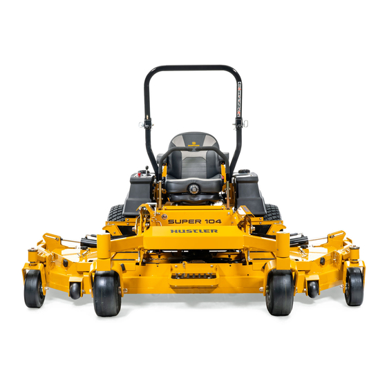
- Page 1 Hustler Super 104 ® General Service Manual 200 South Ridge Road Hesston, Kansas 67062 117364 REV B...
- Page 2 WARNING WARNING The engine exhaust from this product contains chemicals known to the state of California to cause cancer, birth defects or other reproductive harm. NOTICE OF REQUIREMENT OF SPARK ARRESTER MUFFLER This equipment may create sparks that can start fires around dry vegetation. California Public Resources Code Section 4442.6 provides that it is unlawful to use or operate an internal combustion engine on any forest-covered, brush-covered, or grass-covered land unless the engine is equipped with a spark arrester maintained in effective working order.
-
Page 3: Table Of Contents
Table of Contents General Information ........1-1 Service Program. - Page 4 Side Deck Belt Adjustment ......6-5 Deck Troubleshooting ....... . . 6-5 Center Deck Belt Routing &...
-
Page 5: General Information
This manual is part of a service package for the Hustler ® Daily inspect mower for grass clippings and wire and string Super 104 mower. Use of this manual in conjunction with other tangles. The underside of the mower deck will collect a build-up Hustler mower and component manuals will provide the ®... - Page 6 REV B 117364...
-
Page 7: Safety
SAFETY • Refuel outdoors. Never refuel or drain the fuel from the machine indoors. • Never attempt to start engine when there is a strong odor of gasoline or diesel fuel fumes present. Locate and correct cause. This safety alert symbol is used to call attention to a message •... -
Page 8: Operation Precautions
Wrap the blade(s) or servicing. wear gloves and use extra caution when servicing them. Do not touch hot parts of machine. ® Use only genuine Hustler replacement parts to ensure General Maintenance Precautions that original standards are maintained. Maintenance Precautions ... - Page 9 tape openings after adding the inhibitor. Keep container parts water and one part baking soda when they tightly closed when not in use. become corroded. Inspect electrical wiring for worn or frayed insulation. Shorts caused by battery terminals or metal tools touch- Install new wiring if wires are damaged.
- Page 10 REV B 117364...
-
Page 11: Torque
TORQUE Standard Torques The following chart lists the standard torque values for the threaded fasteners found in this manual. Torque all cap screws, nuts and set screws to these values unless a different torque is shown in the Special Torques section. 32.4 IN.-LBS. - Page 12 REV B 117364...
-
Page 13: Power Unit Maintenance
POWER UNIT MAINTENANCE Steering Adjustments this mower. On one seat you will disconnect the mower harness directly from the seat switch as shown in Figure 4-1. On the other seat you will disconnect the wire Steering control lever neutral adjustment harness from the two connectors as shown in Figure 4-2. - Page 14 properly. Figure 4-1 & Figure 4-2 WARNING Do not operate the mower without plugging the mower’s Control wiring harness into the seat switch. This switch is an levers important part of the safety start interlock system. Serious injury can result if the seat switch is not plugged into the mower’s wiring harness.
- Page 15 follow these steps: 1. Shut engine off, place steering control levers in the park brake position, disengage deck clutch, remove ignition Stop screw switch key and disconnect negative battery cable before doing any adjustments. 2. Place the steering control lever in the neutral position. Figure 4-7 3.
-
Page 16: Park Brake Adjustment
Park Brake Adjustment lever to the lower lever the upper control lever can be pivoted to fit the operator’s personal preference (see Figure 4-9). 2. The steering control levers should be adjusted so that WARNING they align vertically with each other when in the neutral position. -
Page 17: Belts
11. Check to make sure all tools or obstructions are removed from under the mower. 12. Raise the rear of the mower and remove the jack stands. Lower the mower. 13. Reconnect the negative battery cable. Bypass valve 14. Lower and secure the seat platform. Bypass valve Jam nuts Figure 4-12... -
Page 18: Hydraulic System
Replace the drain plug before add- Inspect the machine and involve your dealer to resolve ing system oil. the problem. The Super 104 system filter is located inside the hydraulic reservoir on the underneath side of the tank. Use a Hustler ® Bottom View approved filter element only. -
Page 19: Checking The Deck Lift Circuit Pressure
Checking the Deck Lift Circuit Pressure Equipment required: Hustler Pressure Test Gauge Kit, part number ® 601661 Gauge hose Use this procedure when checking the relief setting of the deck lift circuit. 1. With an operator on the seat, place the steering control... - Page 20 Cap the wheel motor ports or fittings. result. 6. Test procedures are the same for both the right and left sides. 7. Install Hustler Test Gauge Kit (p/n 007898) as shown in ® Figure 4-24 and Figure 4-25. Check the bypass valve (tow valve) to make sure it is fully seated.
-
Page 21: New Or Rebuilt Ddc20 Pump Startup Procedure
Always reconnect the seat switch to the mower Figure 4-25 harness. New or Rebuilt DDC20 Pump Startup 2. Remove the Hustler Pressure Test Gauge Kit. ® Procedure 3. After all repairs are completed, check to make sure all... - Page 22 Bypass valve (Tow valve) Seat switch Top of pump Mower Female harness spades Figure 4-27 RH Pump as viewed from rear of mower Figure 4-26 Pump replacement: WARNING This procedure will require that the unit to be raised and blocked up off of the ground. It is necessary for the wheels to rotate without coming in contact with the floor or any object that would permit the unit to propel itself.
-
Page 23: Warner Clutch Re-Gap Adjustment Procedures
properly. Figure 4-27 & Figure 4-28 WARNING Do not operate the mower without plugging the mower’s wiring harness into the seat switch. This switch is an important part of the safety start interlock system. Serious injury can result if the seat switch is not plugged into the Prefill pump mower’s wiring harness. - Page 24 Procedure: WARNING WARNING Do not remove brake pole from field shell/armature. The brake pole tracks match with the clutch brake and need to Always wear adequate eye protection when servicing the continue to match after shim is removed to ensure proper mower.
-
Page 25: Tires
1. Start the engine and the deck should not be engaged with the PTO switch “off” and clutch de-energized. Engage If you wish to use non-pneumatic tires on your Hustler ® and disengage the PTO switch to ensure the proper mower the tires must be an approved tire purchased from function of the clutch. - Page 26 REV B 4-14 117364...
-
Page 27: Engine Maintenance
ENGINE MAINTENANCE General Engine Maintenance Detailed instructions and recommendations for break-in and regular maintenance are specified in the Engine Owner’s manual. Please refer to this manual for engine servicing, lubricating levels with quality viscosity recommendations, bolt torques, etc. The engine warranty is backed by the engine manufacturer. -
Page 28: Carbon Canister
The warranty for air filters expires upon Some Hustler Super 104 mowers will have a carbon canister ® cleaning or servicing in any manner because the condition of incorporated into the fuel system. -
Page 29: Fuel Evaporation System Filter
Fuel Evaporation System Filter Some Hustler Super 104 mowers have a fuel evaporation ® Fuel tank system filter. This filter must be checked and replaced every 500 hours or annually whichever comes first. Figure 1-1 Vapor line Fuel evaporation system filter... -
Page 30: Engine Rpm Settings
Engine RPM Settings The engine rpm’s are set at the factory for maximum mowing efficiency. Occasionally it may be necessary to check and adjust the settings. The high idle speeds, with no load, should be set as follows: Kawasaki FX1000 ENGINE SPEED MODEL NO. -
Page 31: Deck Adjustments
DECK ADJUSTMENTS Deck Leveling WARNING The deck lift mechanism is under pressure. Use cau- tion when performing deck adjustments or mainte- nance. Figure 6-1 Height stop pin Figure 6-2 8. Make sure the deck stop is firmly against the height stop pin. - Page 32 3” Block 3” Block 3” Block 3” Block 3” Block 3” Block A – Measure to top of deck here Figure 6-3 Side view 1/2” Break-over bar Square hole Locator triangle 3” Block 3” Block 1/2” Extension Figure 6-4 5. Lower the center deck to rest against the stop pin. WARNING Stop engine.
- Page 33 Rear wheel 1/2” bolts Jam nut Adjusting bolt Deck lift hanger Figure 6-6 Figure 6-9 adjusted up per Step 12. 12. Adjust the front gauge wheel up or down to satisfy your deck adjustment needs. Adjustments are made by removing the front wheel from the wheel tube and re-arranging the two .125”...
-
Page 34: Blades
(2) .125” (1) .250” (1) .250” (1) .125” Washers Washer Washer Washer (2) .125” (1) .125” (2) .125” Washers Washer Washers (1) .125” Washers (1) .250” (1) .125” Washer (1) .250” (1) .250” Washer Washer Washer Front wheel Front wheel at lowest setting at highest setting Figure 6-10... -
Page 35: Belts
Inspect the belt pulley grooves and flanges for wear. A new belt, or one in good condition, should never run against the bottom of the groove. Replace the pulley when this is the case, otherwise, the belt will lose power and slip excessively. Never pry a belt to get it on a pulley as this will cut or damage Resharpening the fibers of the belt covering. -
Page 36: Center Deck Belt Routing & Tensioning
NOTE: 1. Spring length after tensioning new belt. Measured from outside of hook to outside of hook with deck set at 3¼” (82.6mm) cut height. 2. Route belts as shown. Center Deck Belt Routing & Tensioning 9.3” – 10.3” (236 – 262mm) 7.2”... -
Page 37: Center Deck To Side Deck Belt Routing & Tensioning
Center Deck To Side Deck Belt Routing & Tensioning See Detail B See Detail A Spring length after Adjusting nut tensioning new belt 6.0” ± 0.25” (152mm ± 6.3mm) Jam nut Idler spring Detail A Detail B Figure 6-16 117364 REV B... - Page 38 REV B 117364...
-
Page 39: Electrical
ELECTRICAL Electrical Schematic – Kawaski Main Mower Harness Mowers prior to serial number 13023392 NOTE: If replacing this harness with the updated version the six pin connector pigtail that is attached to the engine will need to be removed. The updated version has individual connections for the following circuits: Charge, Start, Oil Pressure Light, Fuel Solenoid, and Coil Ground. - Page 40 Electrical Schematic – Kawaski Main Mower Harness Mowers with serial number 13023392 and later REV B 117364...
-
Page 41: Electrical Schematic - Briggs & Stratton
Electrical Schematic – Briggs & Stratton Main Mower Harness 117364 REV B... -
Page 42: Electrical Schematic - Side Deck Harness
Electrical Schematic – Side Deck Harness REV B 117364... -
Page 43: Maintenance
MAINTENANCE Maintenance Schedule Figure 4-12, Figure 4-13, Figure 4-14 Figure 4-16 & Figure 4-17 WEEKLY MONTHLY ANNUALLY SERVICE AT OR 50 OR 100 OR 500 INTERVALS INDICATED HOURS HOURS HOURS Verify safety start interlock system Prior to each use Visually inspect unit for loose hardware and/or damaged parts Prior to each use Visually inspect tires Prior to each use... - Page 44 400 hours or 2 years whichever comes first. Check and adjust the spring tension after 50 hours of use as outlined in the Hydraulic Pump Belt Adjustment section of the Super 104 General Service Manual (p/n 117364). Check fuel system for any crack or leaks including, but not limit to, fuel line hoses, fuel valve, vent line hoses, vent valve, vapor valve, carbon canister, and grommets.
- Page 45 Super 104 Maintenance Locator Chart 1. Engine Oil Fill & Dipstick 2. Fuel Filter 3. Engine Air Cleaner 4. Engine Oil Drain Plug 5. Battery 6. Fuel Tanks 7. Hydraulic Oil Reservoir 8. Hydraulic Oil Filter 9. Front Wheel Bearing Zerks (2) 10.
- Page 46 Figure 8-5 1. Engine Oil Fill & Dipstick 15. Pump Belt 2. Fuel Filter 16. Deck Pusher Arm Zerks (2) 3. Engine Air Cleaner 17. Deck Belt - Deck Drive 4. Engine Oil Drain Plug 18. Spindle Housing Zerk (5) 5.
-
Page 47: Troubleshooting
TROUBLESHOOTING The majority of operating problems that occur with a system can be traced to improper adjustments or delayed service. A consistently applied preventative maintenance program will prevent many problems. The following chart is designed to help you locate a problem by suggesting probable causes and the recommended solutions. PROBABLE SUGGESTED SYMPTOMS... - Page 48 PROBABLE SUGGESTED SYMPTOMS CAUSES REMEDIES Uneven cutting height The blade(s) are not sharp Sharpen the blades A cutting blade(s) is/are Install new cutting blade(s) bent The deck is not level Level the deck per the Deck leveling and height adjustment section of the General Service Manual An anti-scalp wheel is not Adjust the height of the...
- Page 49 Cutting blade(s) are damaged or bent. Install new cutting blade(s). A blade spindle is bent. ® Contact your Hustler dealer. The underside of the deck is dirty. Clean the underside of the deck. Cut height is set too high for conditions, causing Reduce deck cut height.
- Page 50 Deck Functionality Symptoms Probable causes Suggested Remedies Grass is not being cut by side deck when mow- Side deck hydraulic cylinders are not fully Fully extend the side deck hydraulic cylinders ing crown of hills or other undulations. extended to allow ±15 degree articulation. using the side deck lift switch.
-
Page 51: Deck Zone Chart
Deck Zone Chart Deck Front Left Right Side Side BLADE IDENTIFICATION TABLE BLADE CHAMBER COLOR BLADE LENGTH (IN) 23.86 20.5 BLACK 20.5 BLACK 20.5 BLACK 23.86 CHAMBER CHAMBER CHAMBER CHAMBER CHAMBER Inches from left edge of cut DETAIL A Deck Front See Detail A Right Left... - Page 52 REV B 117364...
- Page 53 Steering control lever neutral adjustment ........5-3 ............4-3 Fuel evaporation system filter Steering damper ........5-1 ......8-3 General engine maintenance Super 104 Maintenance locator chart ......2-2 ....... 4-7 General maintenance precautions Test procedure for DDC20 pump ........4-6 ............... 4-13 Hydraulic oil heat exchanger Tires ........4-5...
Need help?
Do you have a question about the super 104 and is the answer not in the manual?
Questions and answers