Table of Contents
Advertisement
Quick Links
SERVICE MANUAL
Ver 1.1 2003. 04
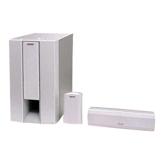
• SA-VE345 consists of the following models respectively.
Active Subwoofer
Front and Surround Speakers
Center Speaker
SA-VE345
For the U.S. model
AUDIO POWER SPECIFICATIONS
POWER OUTPUT AND TOTAL
HARMONIC DISTORTION:
with 8 ohm loads, from 20 – 200 Hz; rated
120 watts per channel minimum RMS power,
with no more than 0.8% total harmonic
distortion from 250 milliwatts to rated
output.
SS-V345 (front and surround speakers)
Speaker system
Full range, magnetically
shielded
Speaker units
5.5 × 11 cm
(2
× 4
in.), cone type
1/4
3/8
Enclosure type
Bass reflex
Rated impedance
8 ohms
Power handling capacity
Maximum input power: 110 watts
Sensitivity level
85 dB (1 W, 1 m)
Frequency range
120 Hz – 20,000 Hz
Approx. 85 × 152 × 112
Dimensions (w/h/d)
mm (3
× 6 × 4
3/8
including front grille
Mass
Approx. 850 g
(1 lb 14 oz) each
Sony Corporation
9-877-088-02
2003D0400-1
Home Audio Company
© 2003. 04
Published by Sony Engineering Corporation
SA-WMS345
SS-V345
SA-WMS345
SS-V345
SS-CN345
SPECIFICATIONS
SS-CN345 (center speaker)
Speaker system
Speaker units
Enclosure type
Rated impedance
Power handling capacity
Maximum input power: 110 watts
Sensitivity level
Frequency range
Dimensions (w/h/d)
Mass
SA-WMS345 (subwoofer)
Speaker system
Speaker unit
Enclosure type
Reproduction frequency range
Amplifier section
in.),
1/2
Continuous RMS power output
SA-VE345/WMS345/
SS-CN345/V345
SS-CN345
Inputs
LINE IN (input pin jack)
Full range, magnetically
SPEAKER IN (input terminals) (US, CND model only)
shielded
5.5 × 11 cm
Outputs (US, CND model only)
(2
× 4
in.), cone type
1/4
3/8
SPEAKER OUT (output terminals)
Bass reflex
8 ohms
General
Power requirements
US, CND model:
85 dB (1 W, 1 m)
AEP, UK model:
90 Hz – 20,000 Hz
AUS model:
Approx. 300 × 81 × 122
SP, MY model:
× 3
× 4
mm (11
in.),
7/8
1/4
7/8
including front grille
Power consumptions
Approx. 1100 g (2 lb 7 oz)
Dimensions (w/h/d)
Active subwoofer,
magnetically shielded
Woofer: 20 cm (8 in.),
cone type
Advanced SAW type
Mass
26 Hz – 200 Hz
120 W (US, CND model)
110 W (AEP, UK, AUS,
SP, MY model)
(8 ohms, 20 Hz – 20 kHz,
0.8% THD)
MICRO SATELLITE SYSTEM
US Model
Canadian Model
AEP Model
UK Model
E Model
Australian Model
120 V AC, 60 Hz
220 – 230 V AC, 50/60 Hz
220 – 240 V AC, 50/60 Hz
110 – 120/220 – 240 V AC,
50/60 Hz
90 W
1 W (standby mode)
Approx. 230 × 392 × 464
mm (9
× 15
× 18
in.),
1/8
1/2
3/8
(US, CND model)
Approx. 230 × 392 × 447
mm (AEP, UK, AUS, SP,
MY model)
including front grille
Approx. 13.2 kg (29 lb 2 oz)
– Continued on next page –
1
Advertisement
Table of Contents

Related Manuals for Sony SA-WMS345


Summary of Contents for Sony SA-WMS345
- Page 1 110 W (AEP, UK, AUS, (1 lb 14 oz) each SP, MY model) (8 ohms, 20 Hz – 20 kHz, 0.8% THD) MICRO SATELLITE SYSTEM Sony Corporation 9-877-088-02 2003D0400-1 Home Audio Company © 2003. 04 Published by Sony Engineering Corporation...
-
Page 2: Table Of Contents
SONT CRITIQUES POUR LA SÉCURITÉ DE FONCTIONNEMENT. NE REMPLACER CES COMPOSANTS QUE PAR DES PIÈCES SONY DONT LES NUMÉROS SONT DONNÉS DANS CE MANUEL Fig. A. Using an AC voltmeter to check AC leakage. OU DANS LES SUPPLÉMENTS PUBLIÉS PAR SONY. -
Page 3: Diagrams
SA-VE345/WMS345/SS-CN345/V345 SECTION 1 DIAGRAMS 1-1. CIRCUIT BOARDS LOCATION (SA-WMS345) POWER board AUTO POWER board LED board MAIN board POWER SWITCH board CONTROL board... - Page 4 SA-VE345/WMS345/SS-CN345/V345 Ver 1.1 • Semiconductor Note on Schematic Diagram: Location • All capacitors are in µF unless otherwise noted. pF: µµF Ref. No. Location 50 WV or less are not indicated except for electrolytics (D101) and tantalums. (D102) • All resistors are in Ω and W or less unless otherwise (D103) specified.
-
Page 5: Printed Wiring Boards (Sa-Wms345)
SA-VE345/WMS345/SS-CN345/V345 Ver 1.1 1-2. PRINTED WIRING BOARDS (SA-WMS345) • Refer to page 3 for Circuit Boards Location. TM101 J101 SPEAKER S701 LINE POWER SAVE MAIN BOARD (CHASSIS) AUTO R702 R709 R705 C516 T501 C502 R711 R101 R114 C102 R121 JW16... -
Page 6: Schematic Diagram (Sa-Wms345)
SA-VE345/WMS345/SS-CN345/V345 Ver 1.1 1-3. SCHEMATIC DIAGRAM (SA-WMS345) D101 R105 D102 IC101(1/2) R101 C101 R111 R106 R203 S201 C209 R103 IC202(1/2) C102 R110 R109 IC203(1/2) TM101 IC201 R201 C204 IC203(2/2) D104 C202 C203 R212 R219 R220 R104 R108 C103 D103 C511... -
Page 7: Exploded Views
AUS : Australian model la sécurité. : Singapore model Ne les remplacer que par une piéce MY : Malaysia model portant le numéro spécifié. 2-1. FRONT PANEL SECTION (SA-WMS345) supplied with RV201 and S201 supplied Ref. No. Part No. Description Remark Ref. -
Page 8: Rear Panel Section (Sa-Wms345)
SA-VE345/WMS345/SS-CN345/V345 Ver 1.1 2-2. REAR PANEL SECTION (SA-WMS345) not supplied not supplied not supplied T601 F601 supplied F602 not supplied T501 not supplied not supplied The components identified by Les composants identifiés par une mark 0 or dotted line with mark marque 0 sont critiques pour 0 are critical for safety. -
Page 9: Center Speaker Section (Ss-Cn345)
SA-VE345/WMS345/SS-CN345/V345 Ver 1.1 2-3. CENTER SPEAKER SECTION (SS-CN345) not supplied not supplied Ref. No. Part No. Description Remark Ref. No. Part No. Description Remark X-4955-358-1 FRAME (CN) ASSY, GRILLE 1-694-516-21 TERMINAL, SPEAKER 4-874-614-21 SCREW (1) (3.5X14), TAPPING A-4736-755-A SYSTEM (CN) ASSY (US,CND,AEP,UK) 1-823-042-11 CORD (WITH C) (US,CND,AEP,UK) A-4737-036-A SYSTEM (CN) ASSY (AUS,SP,MY) 4-986-971-11 SCREW (3.5) -
Page 10: Front And Surround Speakers Section (Ss-V345)
SA-VE345/WMS345/SS-CN345/V345 Ver 1.1 2-4. FRONT AND SURROUND SPEAKERS SECTION (SS-V345) not supplied not supplied not supplied not supplied Ref. No. Part No. Description Remark Ref. No. Part No. Description Remark X-4955-356-1 FRAME (V) ASSY, GRILLE 1-694-516-21 TERMINAL, SPEAKER 4-874-614-21 SCREW (1) (3.5X14), TAPPING A-4736-754-A SYSTEM (V) ASSY (US,CND,AEP,UK) 1-823-042-11 CORD (WITH C) (US,CND,AEP,UK) A-4737-035-A SYSTEM (V) ASSY (AUS,SP,MY) -
Page 11: Electrical Parts List
SA-VE345/WMS345/SS-CN345/V345 Ver 1.1 SECTION 3 AUTO POWER ELECTRICAL PARTS LIST CONTROL NOTE: • Due to standardization, replacements in • SEMICONDUCTORS The components identified by mark 0 or dotted line with mark the parts list may be different from the In each case, u : µ, for example: 0 are critical for safety. - Page 12 SA-VE345/WMS345/SS-CN345/V345 Ver 1.1 CONTROL MAIN Ref. No. Part No. Description Remark Ref. No. Part No. Description Remark R206 1-249-429-11 CARBON 1/4W C304 1-162-282-31 CERAMIC 100PF R207 1-249-437-11 CARBON 1/4W C305 1-162-302-11 CERAMIC 0.0022uF 30% R208 1-249-429-11 CARBON 1/4W C306 1-101-804-00 CERAMIC 10PF 500V R209...
- Page 13 SA-VE345/WMS345/SS-CN345/V345 Ver 1.1 MAIN Ref. No. Part No. Description Remark Ref. No. Part No. Description Remark < IC > R116 1-249-427-11 CARBON 6.8K 1/4W (US,CND) IC101 8-759-145-58 IC uPC4558C R117 1-247-843-11 CARBON 3.3K 1/4W IC102 8-759-145-58 IC uPC4558C R118 1-249-429-11 CARBON 1/4W IC104 8-759-145-58 IC uPC4558C...
- Page 14 0 F601 1-533-418-11 FUSE, GLASS CYLINDRICAL (DIA.5) 1-680-786-11 POWER BOARD (2.5A/125V) (US,CND) 0 F602 1-532-503-31 FUSE (T1.6AL/250V) (SP,MY) ************* 1-529-296-12 SPEAKER (20cm) (WOOFER) (SA-WMS345) < CAPACITOR > 0 T501 1-435-999-11 TRANSFORMER, POWER (US,CND) 0 T501 1-437-219-12 TRANSFORMER, POWER (SP,MY) C401...
- Page 15 SA-VE345/WMS345/SS-CN345/V345 MEMO...
- Page 16 SA-VE345/WMS345/SS-CN345/V345 REVISION HISTORY Clicking the version allows you to jump to the revised page. Also, clicking the version at the upper on the revised page allows you to jump to the next revised page. Ver. Date Description of Revision 2003. 02 2003.